Another axis range Y in WaveformGraph
I am currently in c# to create a WaveformGraph with 2 axes y with different ranges.
Y axis on the first, I have a range from 0 to 80 and on the second, I have a range of-127 to 127.
I created two different axes Y and set the amplitude as a result and they appear right next to the plot.
Then, I created two waveformPlots. An I put the waveformPlot.YAxis.Range to (-127,127) and the other waveformPlot to (0, 80). The problem is when I draw the plot the total range for the plot gets change to (-127, 127) and my (0, 80) plot gets moved up to be in the center of the waveform. I wish that this conspiracy to stay down at the bottom of the chart to match the axis I created.
I can normalize the values but my users use tooltips to get the results of the measures and those who would be most valuable if I subtracted the values 127 in the second waveform.
Well, I managed to figure this out for me. By mistake I had the following code:
waveformPlot1.Yaxis.Range = new range (0, 80);
waveformPlot2.Yaxis.Range = new range (-127, 127);
Instead, I used the two y-axis I already used.
waveformPlot1.Yaxis = yAxis1
waveformPlot2.Yaxis = yAxis2
Tags: NI Software
Similar Questions
-
I created a graph xy with two value axes and associated y scale index 0 (Plot.YScaleIdx) locations 0-5 and plots of 5 to 11 with indication of scale is 1. I would like to change the minimum and the maximum of each of the beaches there by program. I tried do different plots (associated with different axes) by default and by changing the YScale.Range.Minimum or the YScale.Range.Maximum property. But it still affects the same scale that any field is the default value. Can someone tell me how to select the scale are affecting these properties?
Using LabVIEW 2012 32-bit on Windows 7.
Tom
If I understand correctly, you must set the Active Y scale property before changing the parameters of this scale.
-
Table axis range error labview
Hello
I'm trying to programmatically set the chart to display a minute 30 or 60 minute range. I can do this by setting the following in a case manager properties, if the user presses a button to apply the settings of the map (with the display of absolute time format):
Entry: graph time = 30 minutes or 60 minutes
Properties (in order):
Scalefit value of 0 (no autoscale)
Offset of the value timestamp 'get the current time.
Startrange value timestamp 'get the current time.
Multiplier to 1 /(1000 Samples)
Minimum for the timestamp 'get the current time.
Maximum to 'Get the current time' + 1800s (for table duration = 30)
Loosefit set to true
Result:
While I can get the output offset table correctly, the time slot is always set to 40 minutes.
I ask these same settings in the table more away in the loop and the min, max values are completely different - one offset is consistent.
Here is a sample run: table length = 60,.
Minimum = 15:01 25 January 2013
Maximum = 16:01, 25 January 2013
Offset = Minimum
Output:
Minimum = 15:02 January 25, 2013
Maximum = 15:42 25 January 2013
Offset = 15:01 25 January 2013
I am confused because I have not set these properties of chart in my code otherwise. No idea where they come from? One solution is to take the code in the case manager, but I would like to refrain to do so because it uses more memory. Thank you!
Could you post an excerpt of our VI? It would be very useful.
Right on the top of my head, I think you may have a problem with the amount of data in the table and affecting the size. You may also need to set the length of the history of the chart.
You might be better off using a graph of waveform instead of graph. It is much easier to control the data in a chart as you define explicitly all the data instead of letting the LV to annex all automatically.
-
Is there a way to get the gradient fill to move on another axis?
If I try to add a gradient in a rectangle fill, so the gradient always goes from left to right (or right to left if I reverse the gradient) but y at - it a way to get the slope to go from the bottom to the top of the rectangle (and conversely from the top to the bottom of the rectangle)?
Change the angle to be 90 or - 90.

You can also use the gradient tool to change the direction/start and endpoint of your gradient.
-
Axis changes after a set interval
I have change my X axis range programmatically in various circumstances in my program. After the range changes, the method, and then calls another method to plot data. However, when I get the new method, the new range now has what I set the minimum or maximum. Why the range changing on me?
Hello
You set the mode to fixed axis?
ScatterGraph1.XAxes.Item (0). Mode = AxisMode.Fixed

ScatterGraph1.XAxes.Item (0). Range = new range (0, 10)
Curt
-
ScatterGraph does not manually change the axis to execution interval
I use the ScatterGraph and the WaveFormGraph in VS2010 Winforms application. I have the interaction mode axes set to EditRange. The WaveFormGraph command allows to edit the axis range by clicking on the end of the axis labels and modify them. ScatterGraph control is not even though the documentation I've read says it should. The mode of the axis does not seem be the question that I have changed between fixed and AutoScaleLoose (which is not the choice to have everything showing changing data, if you want your range entered manually to maintain). I tried a new project with a ScatterGraph control with the default settings and checked that it does not change the axis interval. Is there a way to change the settings to allow you to manually edit a ScatterGraph range in this way when running?
Thank you!
Hi Lybro,
You have activated the "EditRange" of the graphical object of point clouds InteractionMode? There are two places that the mode of interaction is defined, one for the axis and the other for the scatter chart, both must be enabled for writing at work. I just tested this with Measurement Studio 2013 and it works. Let me know if it helps.
Kind regards
Kevin
-
Hide the first and the last Division in the WPF chart axis
I want to hide the default marker of the first and the last major division in an axis of a chart of WPF. I tried to extend RangeDivisionsMode and define my own class object to the MajorDivisions.Mode property on the axis. But even when I returns a list empty in RangeDivisionsMode.GetDivisions
(...) , the first and the last marker is drawn.Thanks in advance, Jonas
The minimum and maximum labels are transmitted separately when displaying a scale (even if technical
RangeDivisionsModecustom can be used for the minor divisions).There is no direct configuration option to hide extreme labels, but you can achieve this effect by initializing the
LabelPresenterproperty onMajorDivisionsby a custom implementation:class CustomFormatter : GeneralValueFormatter {
protected override UIElement VisualizeCore( TData value, ValuePresenterArgs args, UIElement existingVisual ) {
UIElement element = base.VisualizeCore( value, args, existingVisual ); var axis = (Axis)args.Context;
Rangerange = axis.Range;
var comparer = range.Comparer;
bool isExtreme =
comparer.Compare( range.Minimum, value ) == 0
|| comparer.Compare( range.Maximum, value ) == 0;
element.Opacity = isExtreme ? 0.0 : 1.0;return element;
}
} -
AutoScale after Zoom Pan and change the axis interval
I'm trying to connect the axes x many ScatterGraphs and I was wondering how to restore the graphics to their original point of view drawn once a user has made a lot of zoom, pan and axis range chages. Basically how do you perform an autoscale on one axis without having to cancel each operation individually. In the old graphic activex controls, there is an AutoScaleNow function that has done this.
Also, how to cancel a change of range that has been achieved through code? If interactively modify you a range, it seems the SHIFT-RIGHT CLICK to cancel the operation. If the event of range change is captured and applied to the other charts, it can not be canceled.
Use ScatterGraph.ResetZoomPan () to cancel all zoom, pan and change of range in a scattergraph operations. This will cancel the range changes made in the UI, but not changes made through code. To changes in the code, you will have to manage undo operations. You can store the original lines and go back to those who, when necessary. Or you can force a re-AutoScale by changing the mode of scale axis as shown below:
scatterGraph1.XAxes [0]. Mode = NationalInstruments.UI.AxisMode.Fixed;

scatterGraph1.XAxes [0]. Mode = NationalInstruments.UI.AxisMode.AutoScaleLoose;

scatterGraph1.YAxes [0]. Mode = NationalInstruments.UI.AxisMode.Fixed;

scatterGraph1.YAxes [0]. Mode = NationalInstruments.UI.AxisMode.AutoScaleLoose; -
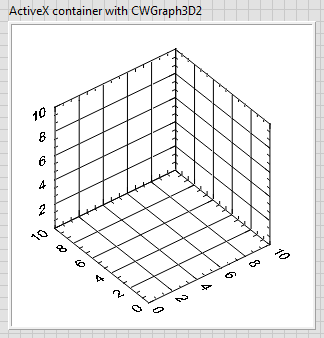
gone 3D reverse chart axis option
I want to programattically must reverse the axes X and Y of a plot 3D to answer the orientation of my installation. In older versions of labview, it was possible but now in 2013, this option seems to have disappeared. 2013 using a function called is mentioned "axis: range: range inverted", but he's not here.
He returned in a new update soon?
Kind regards
Martin
Hello Martin,
I'm glad that you were able to locate the property. The difference between the 2 garphs is that the 3-d chart of Surface (using) uses ActiveX and is supported only on Windows OS. The other chart (which I used) looks more like a native control of LabVIEW. The differences are detailed here.
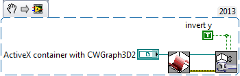
I don't know why the axis reversal property is not exposed, or if it will be in future versions, but here is a quick work around. Place a container ActiveX on your façade. Right-click on it and select Insert ActiveX object. In the dialog box that pops up select CWGraph3D control. This should give a similar 3D-graphics on your front, you're used to using.
On the block diagram, you will get a 3-d chart reference ActiveX. That you can use to manipulate the graph using 3D graph properties screws (range of functions > programming > graphics and sound > 3D graphical properties). To invert the axis, you can do something like this.
If you notice the data that you provide to draw remain same in your approach and this workaround.
I hope this helps.
Kind regards
Michel
-
Try to convert the partitioned Table of interval in the range... Swap partition...
Requirement:
Interval of replacement partitioned Table by range partitioned Table
I need to change this partitioned Table apart to a partitioned range Table. I can do using the EXCHANGE PARTITION. Like if I use the classic method to create another table range partitioned, then:DROP TABLE A; CREATE TABLE A ( a NUMBER, CreationDate DATE ) PARTITION BY RANGE (CreationDate) INTERVAL ( NUMTODSINTERVAL (30, 'DAY') ) (PARTITION P_FIRST VALUES LESS THAN (TIMESTAMP ' 2001-01-01 00:00:00')); INSERT INTO A VALUES (1, SYSDATE); INSERT INTO A VALUES (1, SYSDATE - 30); INSERT INTO A VALUES (1, SYSDATE - 60);
Problems:DROP TABLE A_Range CREATE TABLE A_Range ( a NUMBER, CreationDate DATE ) PARTITION BY RANGE (CreationDate) (partition MAX values less than (MAXVALUE)); Insert /*+ append */ into A_Range Select * from A; --This Step takes very very long..Trying to cut it short using Exchange Partition.
I can't do
ORA-14095: ALTER TABLE CHANGE requires a not partitioned table nonclusteredALTER TABLE A_Range EXCHANGE PARTITION MAX WITH TABLE A WITHOUT VALIDATION;
This is because the tables are partitioned. So it does not allow me.
If I instead:
Create a table that is not partitioned for exchanging data by partition.
-The problem is that all the data is in MAX Partition.Create Table A_Temp as Select * from A; ALTER TABLE A_Range EXCHANGE PARTITION MAX WITH TABLE A_TEMP WITHOUT VALIDATION; select count(*) from A_Range partition(MAX);
Even after the creation of a large number of partitions by walls of separation, the data is still in MAX Partition only.
So:
-What we cannot replace a partitioned Table to the Table partitioned using the EXCHANGE PARTITION range interval. that is, we have to insert in...
-We can do it, but I'm missing something here.
-If all the data is in MAX Partition due to "WITHOUT VALIDATION", can say us be redistributed in the right type of range partitions.You must pre-create the partitions in a_range and then swap one for one for a tmp, and then to arange. With the help of your sample (thanks to proviing code, incidentally).
SQL> CREATE TABLE A
  2  (
  3     a              NUMBER,
  4     CreationDate   DATE
  5  )
  6  PARTITION BY RANGE (CreationDate)
  7     INTERVAL ( NUMTODSINTERVAL (30, 'DAY') )
  8     (PARTITION P_FIRST
  9         VALUES LESS THAN (TIMESTAMP ' 2001-01-01 00:00:00'));

Table created.

SQL> INSERT INTO A VALUES (1, SYSDATE);

1 row created.

SQL> INSERT INTO A VALUES (1, SYSDATE - 30);

1 row created.

SQL> INSERT INTO A VALUES (1, SYSDATE - 60);

1 row created.

SQL> commit;

Commit complete.
You can find the form of existing partitions assistance:
SQL> select table_name, partition_name, high_value
  2  from user_tab_partitions
  3  where table_name = 'A';

TABLE_NAME PARTITION_NAME HIGH_VALUE
---------- -------------- --------------------------------------------------------------------------------
A          P_FIRST        TO_DATE(' 2001-01-01 00:00:00', 'SYYYY-MM-DD HH24:MI:SS', 'NLS_CALENDAR=GREGORIA
A          SYS_P44        TO_DATE(' 2013-01-28 00:00:00', 'SYYYY-MM-DD HH24:MI:SS', 'NLS_CALENDAR=GREGORIA
A          SYS_P45        TO_DATE(' 2012-12-29 00:00:00', 'SYYYY-MM-DD HH24:MI:SS', 'NLS_CALENDAR=GREGORIA
A          SYS_P46        TO_DATE(' 2012-11-29 00:00:00', 'SYYYY-MM-DD HH24:MI:SS', 'NLS_CALENDAR=GREGORIA
You can then create the table a_range with apporopriate partitions. Note that you may need to create additional in a_range partitions because the partitioning interval does not create the partitions has no data for, even if that leaves 'holes' in the partitioning scheme. So, on that basis:
SQL> CREATE TABLE A_Range (
  2     a NUMBER,
  3     CreationDate DATE)
  4  PARTITION BY RANGE (CreationDate)
  5     (partition Nov_2012 values less than (to_date('30-nov-2012', 'dd-mon-yyyy')),
  6      partition Dec_2012 values less than (to_date('31-dec-2012', 'dd-mon-yyyy')),
  7      partition Jan_2013 values less than (to_date('31-jan-2013', 'dd-mon-yyyy')),
  8      partition MAX values less than (MAXVALUE));

Table created.
Now, create a regular table to use in the constituencies:
SQL> CREATE TABLE A_tmp (
  2     a              NUMBER,
  3     CreationDate   DATE);

Table created.
and all partitions in Exchange:
SQL> ALTER TABLE A
  2    EXCHANGE PARTITION sys_p44
  3    WITH TABLE A_tmp;

Table altered.

SQL> ALTER TABLE A_Range
  2    EXCHANGE PARTITION jan_2013
  3    WITH TABLE A_tmp;

Table altered.

SQL> ALTER TABLE A
  2    EXCHANGE PARTITION sys_p45
  3    WITH TABLE A_tmp;

Table altered.

SQL> ALTER TABLE A_Range
  2    EXCHANGE PARTITION dec_2012
  3    WITH TABLE A_tmp;

Table altered.

SQL> ALTER TABLE A
  2    EXCHANGE PARTITION sys_p46
  3    WITH TABLE A_tmp;

Table altered.

SQL> ALTER TABLE A_Range
  2    EXCHANGE PARTITION nov_2012
  3    WITH TABLE A_tmp;

Table altered.

SQL> select * from a;

no rows selected

SQL> select * from a_range;

         A CREATIOND
---------- ---------
         1 23-NOV-12
         1 23-DEC-12
         1 22-JAN-13
John
-
active member directory; range = 0-999 issue
Someone else had a problem with active directory, and it returns the Member with the attached range attribute? I'm running on this issue, as mentioned in an article in microsoft (see below). The data comes back very well and I get all the records that I need. BUT... the problem is the column name is returned as "Member; interval = 0-999"instead of just member as in a normal query ActiveDirectory. The problem is that it has this semicolon in the name of the column in an attempt to loop through the query or access this data keeps breaking it. So this is, I can't do it. I tried to escape the semicolon or the column name aliasing, but I just keep running into problems. I hope that someone else has to face this or knows ways around the invalid column names in a query. If I have a result set for a query that has a bad column name, how can I get this data?
When an Active Directory server returns the values of the attribute member as a result of a directory search query, its behavior varies depending on whether the total number of values of attributes for this object exceeds the maximum limit on the values retrieved. For example, if a distribution on a Windows 2000 Server list contains values of Member of 1000 or less, a search query will return all the values in a single call. However, if the list contains values of Member of 2497, the first call to the function of search query returns the Member with no value attribute and another Member; range = 0-999 attribute that contains the first values of 1000 members. To retrieve the next group of member values, the search query should be repeated using a range specifier that begins on the issue past a returned attribute the number of the previous group. In this example, the search query service would ask the Member; interval = 1000-* values that return the Member; range = 1000-* attribute with no value and Member; range = 1000-1999 with values then 1000 attribute. This process is repeated until the last group of values is retrieved. End of beach on the last group retrieved from the server would be indicated by an asterisk (*) in the name of the attribute returned.
I found, I was able to solve this problem by using the method that is located at the following address: http://www.bennadel.com/index.cfm?dax=blog:357.view
-
Performance problem, same range scan different execution time
Oracle 11 GR 1 material, execute queries within seconds of each other.
I have 2 questions that are logically the same. Even the explain command plans are very similar, except the other indicates a range index scan doing much more work than the first. The table is an IOT with deal_bucket_id and datetime as PK (in that order).
TKPROF output below:
select count(*) from deal_bucket_detail where deal_bucket_id
How can I work on why the second query is much more work than the first?
in
(815
, 816
, 817
, 818
...
, 997)
and datetime between to_date('01-JUL-08','dd-MON-rr') and to_date('01-JAN-09','dd-MON-rr')
call count cpu elapsed disk query current rows
-----------------------------------------------------------------------------------------------------
Parse 1 0.00 0.00 0 0 0 0
Execute 1 0.00 0.00 0 0 0 0
Fetch 2 0.79 2.24 2936 3551 0 1
-----------------------------------------------------------------------------------------------------
total 4 0.79 2.24 2936 3551 0 1
Misses in library cache during parse: 1
Optimizer mode: ALL_ROWS
Parsing user id: 43
Rows Row Source Operation
------- ---------------------------------------------------
1 SORT AGGREGATE (cr=3551 pr=2936 pw=2936 time=0 us)
1430928 FILTER (cr=3551 pr=2936 pw=2936 time=380920 us)
1430928 INLIST ITERATOR (cr=3551 pr=2936 pw=2936 time=372057 us)
1430928 INDEX RANGE SCAN PK_DEAL_BUCKET_DETAIL (cr=3551 pr=2936 pw=2936 time=8782 us cost=1203 size=4069596 card=339133)(object id 14199)
Elapsed times include waiting on following events:
Event waited on Times Max. Wait Total Waited
---------------------------------------- Waited ---------- ------------
SQL*Net message to client 2 0.00 0.00
db file sequential read 2936 0.02 1.49
SQL*Net message from client 2 0.00 0.00
********************************************************************************
select count(*) from deal_bucket_detail where deal_bucket_id
between 815 and 997
and datetime between to_date('01-JUL-08','dd-MON-rr') and to_date('01-JAN-09','dd-MON-rr')
call count cpu elapsed disk query current rows
-----------------------------------------------------------------------------------------------------
Parse 1 0.00 0.00 0 0 0 0
Execute 1 0.00 0.00 0 0 0 0
Fetch 2 3.70 8.86 29199 26986 0 1
-----------------------------------------------------------------------------------------------------
total 4 3.70 8.86 29199 26986 0 1
Misses in library cache during parse: 1
Optimizer mode: ALL_ROWS
Parsing user id: 43
Rows Row Source Operation
------- ---------------------------------------------------
1 SORT AGGREGATE (cr=26986 pr=29199 pw=29199 time=0 us)
1430928 FILTER (cr=26986 pr=29199 pw=29199 time=6986078 us)
1430928 INDEX RANGE SCAN PK_DEAL_BUCKET_DETAIL (cr=26986 pr=29199 pw=29199 time=6977063 us cost=45208 size=5195748 card=432979)(object id 14199)
Elapsed times include waiting on following events:
Event waited on Times Max. Wait Total Waited
---------------------------------------- Waited ---------- ------------
SQL*Net message to client 2 0.00 0.00
db file sequential read 219 0.04 0.08
db file parallel read 35 0.04 0.32
db file scattered read 211 0.10 5.02
SQL*Net message from client 2 0.00 0.00
********************************************************************************
Published by: SamB on August 5, 2009 18:09The two make an index range scan, but another index range scan.
Query 1: inlist iterator withrange of index analysis for 1 value, because of the hard-coded values.
Query 2: analysis of range of index for all values, starting at the bottom, thanks to between.-------------
Sybrand Bakker
Senior Oracle DBA -
Draw a line connecting two points in the WPF chart
I'm trying to understand the best way to draw a line between two existing points on my graph in WPF. At first, I thought I had it works fine; I just added another parcel to my graph then given exactly two points for rendering. But I quickly noticed that the app has become surprisingly slow and CPU was quite high (adding other plots does not affect the use of the CPU as long as they have a complete set of points (?)). He wants me if I looked at using the DataToScreen method on the chart but I can't know what the parameters are. The second parameter is simply an IList that tells me a lot. This seems to be the method I want to use for the coordinates of a point on the graph screen.
No one knows what the second parameter is supposed to be for the DataToScreen method? Everything I tried throws an Exception of Argument.
Thank you
DanDataToScreenwill return a screen coordinate in the plot area of a chart of the value of the raw data horizontal and vertical in the given list. The parameter value is aIListfor compatibility with other methods of graphical query such asFindNearestValue, returnIListvalues containing raw data.A concrete example, say you had a graphical configuration with a wide horizontal axis ranging from 0 to 100 and a vertical axis double precision ranging from 10 to 20:
To get the screen coordinates of the value at the center of the two axes, you can call:
graph.DataToScreen(plot, new object[] { 50, 15.0 })Note that the raw data values corresponding to the type of axes (horizontal
AxisInt32returns the integer50and verticalAxisDoubleGets the value15.0).You also mentioned a performance issue where "adding other plots does not affect the CPU so that they have a complete set of points". I did a simple test app that adds an array of two points of a chart on each key (for example
graph.Data.Add(new[] { new Point(x1, y1), new Point(x2, y2) });), but could not reproduce the problem you saw. Could you share the code, you use to draw the connection line? -
Align WPF elements with the plot area
Is there a recommended way to align WPF elements outside the graph with the plot area? I like my UI align the left edge of area of land. Another use case is lining up outside elements with a RangeCursor.
The way we do now is to add a canvas as a child of the graph. The canvas contains a hidden Visual position ourselves with Canvas.SetLeft using values calculated from the graph margin and padding. Then, we call PointToScreen (new Point (0,0)) on the display. It works most of the time, but the position of the Visual sort of trolling the real edge graphic when the y-axis range changes (and a few other changes axis, that I've not completely nailed down). By calling UpdateLayout on the display when the range changes, I can make it work most of the time, but when I do that, I find that I spend a lot of time CPU in the user interface thread to this appeal.
Currently, the graph does not directly expose the offset of the plot area in the border of the control. Your method of using a nested Visual to calculate the offset appears as a reasonable approach with the current API. I created a quick mock-up using this approach for certain forms of referring to the plot area and a range slider:
XAML
Code
public partial class MainWindow : Window {
private static readonly RangeRelativeRange = new Range ( 0.0, 1.0 ); public MainWindow( ) {
InitializeComponent( );rangeCursor.HorizontalAxis = xAxis;
rangeCursor.VerticalAxis = yAxis;
}private void OnGraphLayoutUpdated( object sender, EventArgs e ) {
UpdateAlignment( );
}private void UpdateAlignment( ) {
Size size = graph.RenderSize;
if( size.Width <= 0.0 || size.Height <= 0.0 )
return;// Get reference point to canvas in bottom-left corner of graph.
var referenceTransform = referenceVisual.TransformToVisual( graph );
Point graphBottomLeft = referenceTransform.Transform( new Point( ) );// Apply margin to size and bottom-left reference point.
Thickness margin = graph.Margin;
size.Width += margin.Left + margin.Right;
size.Height += margin.Top + margin.Bottom;
graphBottomLeft.X += margin.Left;
graphBottomLeft.Y += margin.Top;// Calculate top-right reference point.
Size plotAreaSize = graph.GetPlotAreaSize( );
Point graphTopRight = new Point(
graphBottomLeft.X + plotAreaSize.Width,
graphBottomLeft.Y - plotAreaSize.Height );// Get reference points for range cursor within plot area.
var horizontalRange = rangeCursor.GetRelativeHorizontalRange( ) ?? RelativeRange;
var verticalRange = rangeCursor.GetRelativeVerticalRange( ) ?? RelativeRange;
Point cursorBottomLeft = graph.RelativeToScreen( new Point( horizontalRange.Minimum, verticalRange.Minimum ) );
Point cursorTopRight = graph.RelativeToScreen( new Point( horizontalRange.Maximum, verticalRange.Maximum ) );
cursorBottomLeft.X += graphBottomLeft.X;
cursorBottomLeft.Y += graphTopRight.Y;
cursorTopRight.X += graphBottomLeft.X;
cursorTopRight.Y += graphTopRight.Y;// Set margin to align graph and cursor visuals.
graphTopRectangle.Margin = new Thickness { Left = graphBottomLeft.X, Right = size.Width - graphTopRight.X };
graphLeftRectangle.Margin = new Thickness { Top = graphTopRight.Y, Bottom = size.Height - graphBottomLeft.Y };
cursorBottomRectangle.Margin = new Thickness { Left = cursorBottomLeft.X, Right = size.Width - cursorTopRight.X };
cursorRightRectangle.Margin = new Thickness { Top = cursorTopRight.Y, Bottom = size.Height - cursorBottomLeft.Y };
}
} -
attempt to create LEGO-dust or sort of LEGO explosion.
The brick is made in one minute (see preview screen Center), but when I do the group a cell particle is "flat":

Although 3D, looks like it turns only around an axis... (??)
tried various settings - no hope.
Someone at - it advice?
Sorry, but the way that you set it to the top will not work. The 3D groups used as source for the cell particles get flattened, it has always been thus.
By example, if you have 3 circles separated on Z in a 3D group and create a transmitter out of this group, the source of the cells still gets flattened, you don't actually have a particle composed of 3 circles of offset. You get a particle of cells that are flat, but the transmitter can project them in 3D space. For text 3D, if you use the object text 3D (single layer) as the source it will provide no flattened in the transmitter.
That said, there is an "easy way" to do this and hard a way. First of all easy:
1. set up your "Trade marked building block" in a group and Center it in the group.
2 animate the rotation on two of the chains of the Group (X / Y for example). I used the behavior of rate with slightly different values.
3 export this output as a movie, and then import it into the movement.
4. use the film as the source of the issuer. Make sure that the random boot image is checked in the settings of the transmitter.
-You may need to adjust the rotation speed. I used this method to create particles of blood cells in the past and it worked fine.
Pros: Simple configuration works in most cases. Faster and better performance.
Disadvantages: Not true 3D, you must perform a new rendering of the sources of the cell if you need to change the items.
90% of the time that this method will be good enough.
Here's the hard, but it has limits (I'll get to those).
1. in a new group, create your basic "box" using text in 3D. Using the commands to set layer transformation origin (Center of the world) on XYZ, is visually very well.
2. based on the Properties tab, move the anchor point for the box originally as well. Check the position of the top, front and one side. You can reduce the opacity to see the grid in 3D.
3. now, create a new text layer object to be the 'peg '.
4. use the rotation settings in the appearance tab text to get the ankle facing the correct direction, associated with the box.
5. move the layer 'peg' in the right position related to the area using the 3D transformation controls.
6. once in place, select the layer and again move the anchor point toward the center of the world.
You have now two objects which will have all created transformations effectively from the same point. The shared location of anchor is essential to make it work.
7. Select the first box and create a 3D with that issuer.
8 copy the random start in the control of the cell value. You will need it for each post.
9. drag the layer peg on the transmitter, which will create a new cell.
10. glue the random seed value in the box, the cell in peg.
Here is where I would test the basic settings.
IMPORTANT: THE VALUES IN CELL OR CHANGES NECESSARY TO EVERY CELL AND MATCH FOR ALL THE CELLS IN THE TRANSMITTER.
For each cell in the change in the rate of birth to something low (I used 2) so you can see what is happening. Reading and verification of the animation. If everything is configured correctly (original anchor point points are at 0,0,0 in the values of the world, random seed for the match of cells) that you will have the pegs that stick to the boxes. If things don't stick you probalby have problems with the anchor positions (they do not match) or values of cells.
Once you have set up the first peg and know that it works, you can add extra pegs by using the previous steps. Then check that the anchors are centred and correspond to cell values. for each cell in the transmitter.
So here are the limits.
- Easy to break delicate installation (but not too bad).
- If you wish the transmitter to turn cells, they will turn only on a single axis (z). You can work around that, by linking the rigging the rotation of text object layer together values and then animate these on another axis, as Y. However, this will affect all cells in the transmitter, so things a still fairly uniform. To work around this problem, you can duplicate the text layers, create an another particle emitter with a few shifts (birth rate, direction of rotation, speed). When played together, they will look more random.
Again, the most important thing to get this second method works is paired things (anchor points, the layer changes, cell parameters). Knowledge of the rigging/link can help. FWIW, this configuration can also be much more intensive treatment depending on the purpose of text how he takes and create the number of particles, your mileage may vary (this is why there is the easy way).
Good luck!


Maybe you are looking for
-
I can't install the latest iTunes on my pc windows 10.
I can't install the latest iTunes on my computer windows 10. I tried everything according to this: https://support.apple.com/en-us/HT201668. The error that says: "there is a problem with this windows package install." "A program required for this ins
-
HP 7510 AIO printer won't connect - Wired workstation, printer wireless
Hello! I'm talking about (and verified solution button) too early. The printer still "disappears" from the wired network XP workstation. The only difference as apply the given solution is that disconnect it now happening about every 12 hours, agains
-
HOW TO ERASE ALL THE NAMES AND START OVER IN OUTLOOK EXPRESS? I've listed six identities, none work for sending emails via Outlook Express. How can I clear all of these ID out when I get the message: no current identity? So how can I load this new
-
Mail blocked mail? -10 message number could not be found - error number: 0x800420CD
Hi, I keep grtting this error message any ideas how to fix it please Number 10 of the message could not be found. Account: 'pop3.btconnect.com', server: 'pop3.btconnect.com', Protocol: POP3, server response: 'More, show this email to your advisor for
-
How can I remove Sidekick plugin
help me get rid of the sidekick plugin. I don't know how this on my computer but I do not love. It interferes with what I see on Facebook, etc.