Calculation of RMS
Hi all
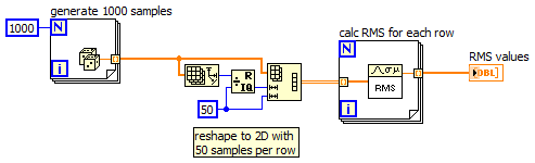
Please find the attached VI, I am computing the RMS for the first 20 values of amplitude. I want to reiterate this RMS calculation for every 20 samples until the end of the data samples. Suppose I have 1000 data samples, I should be able to draw on the graph of 50 points of RMS. Advice on how to go about it. Excuse me if I missed anything.
Thanks in advance,
Hey Kevin,
Try this:
Tags: NI Software
Similar Questions
-
Weighted Bandlimited a calculation of rms noise
Hi all
I want to calculate the band including a weighted rms noise. I'm able to calculate noise from rms to an analog signal without any bandwidth limitation. Find the attached vi for details. I want to limit the bandwidth to some known values (say 20 Hz to 20 kHz) and then calculate the rms noise.
Please advice.
Thank you best regards &,.
Siva
Siva,
What is the problem you are having?
I do not have the Sound and Vibration Toolkit, but when I replace it with a filter from the palette of Signal Processing, I get changes in bandwidth and in the calculation of rms. The RMS.vi of the mathematics > probability & statistics palette produces the same value you use the VI of statistics. Based on average DC - RMS.vi Signal Processing > range of measures of waveform produced smaller values on the 3 orders of magnitude.
Lynn
-
Sorry for the use of this thread I can't find a way to post new problem.
How amplitude and level VI calculates RMS calue for multi-frequency signals. For your unique, Vrms = Vpeak/sqrt (2) gives same result but for multi-frequency signals, is not match with 'amplitude and level measurement VI' calculated RMS. I need formula to calculate the effective value for calculations PAPR multi-frequency signal. I need RMS formula for multitone to apply the PAPR calculation in hardware.
Attached code shows calculation of the PAPR by using different values of the RMS. Only calculation RMS Labview gives good results as comapare to "Vrms = Vpeak/sqrt (2).
RMS = SQRT (SUM(X^2) (X) /sizeof)
If only it turns out that for a full cycle of a sine wave, the RMS turns into Vpeak/sqrt (2). For anything else, you must go through the full definition of the RMS to compute.
-
PCI-6110 - calculated resolution RMS
We have a requirement for the resolution of measurement of voltage AC RMS. I am in a position a repetitive alternating signal with 512 samples on 1 cycle using the range full scale. I then calculate the value of these data. What is the effective resolution of the RMS measurement? Should not 512, 12-bit samples (signal varies for each sample) produce a measure of 12-bit resolution? How can calculate the actual resolution of bit RMS?
I don't see how it takes into account the benefits obtained with various LSB errors between samples.
The best I can determine via Google is the increase of the resolution for a simple average is the square root of the number of samples. So 512 samples would result in improved time 22.6 (adds 4.5 bits). The improvement of a quadratic average is probably different (less), but my test here with real hardware is in this stadium. Google also revealed that some applications intentionally add a small amount of random noise, resulting in a dramatic improvement in the calculation the resolution.
-
Calculation of RMS through a rectangular window with gap of time 25%
Any signal (for example the sinuses), I need to calculate the RMS value, with an integration time of 1 millisecond , through a rectangular window, with a gap of 25%.
In other words, instead of calculate an RMS value by considering every 1 ms interval, I need to calculate the value of a 1 ms window, then apply a gap of time 25% (of the window) and calculate the next RMS value assuming a 1 ms interval and so on.For example, in a 1 ms window, there is a 75% overlay.
I appreciate all help.
Thank you in advance.
Hello.
It has been long since I last posted something.
I managed to get what I wanted, now I need to optimize it.
I simulate a sinusoidal signal and I get a 1 MS integration time 't' just setting the number of samples n and the "fs" sampling rate (fs = N / t <=>t = N / fs). Can I use the tool "Extract the Signal Portion" and I calculate the effective value of the part in a loop.
Anyone know if there is a way to do the same thing without the 'extracted signal part', because this tool using too much memory if the duration of the treatment is just too long with 4 k samples and 4 M samples/second.Thank you.
-
How for-loop to calculate RMS with length of 100 samples window and step 1 sample window
Hello world
I'm trying to make a transition from Matlab to Labview signal processing needs... Specifically, I need to smooth out and quantify a randon, two-phase sampling signal ~ 128000 in length... In matlab, I so calculate the RMS with a length of 100 samples window and no window of 1 sample to smooth.linear evelope signal; do my calculations of amplitude...
I have a problem to do in Labview... The matlab code that I would use normally is:
___________________________________________________________
Variables to assign % RMS
x = signal of interest;
window_length = 100;
window_step = 1;
Calculation of % RMS
EMG = x ^ 2.
index = 0;
nWindows = floor (nrows - (window_length - window_step)) / window_step;
EMG_rms = zeros (nwindows, matches); % The pre-allocating memory
j = 1:window_step:length (EMG) - window_length + 1;
index = index + 1;
EMG_rms (index,
 = sqrt (average (EMG (j: j + window_length-1,));))
end
________________________________________________________
I tried many times with the loop for, but no luck... Ingore smileys... They must be a colon (:, to indicate all lines) followed by a)...
Any suggestions?
Thank you
-
Hello
I have a question which I can not resolved. I used the function calls ChnRMS (XW, Y, E, RMSWidth) and users if they wish, can change the RMS width in percentage. But now they want to specify the width in milliseconds and I need a script for milliseconds in percentage change. What can I do?
Thank you.
Sara
Hi Sara,.
You can convert the time window in seconds to the window required in % with the following equation:
L1 = NOC ("Time_Front")
% = (CMax (L1) - CMin (L1)) * SampleRate_/100It would also be possible to create a custom dialog box that does this automatically and have your username jump to the top of this dialog box instead of the RMS ANALYSIS dialog box, but there is no way to customize the appearance or behavior of a function of ANALYSIS expedition. We could take hostage the ANALYSIS icon for the calculation of RMS and have this call to the top of your custom dialog box, though.
Brad Turpin
Tiara Product Support Engineer
National Instruments -
Calculation of signal to noise ratio
Hello.
I was wondering if it was possible to calculate the SNR of a signal with LabView? I use a DAQ hardware and an accelometer to measure a force.
Is that being said, possible to calculate SNR by looking at the graph of spectrum or vague? When there is no g on the accelerometer, there is a signal with a little noise... and I can see that in the spectrum of frequecny all the way to the cut-off frequency. What is the background noise?
I'd appreciate any help!
Thank you!!
Abraham_E,
Thanks for the data. Curiously, the data do not seem to care what language you were using when you got it.
The first data column appears as timing information. The dt in who is 0.0005, which corresponds to a frequency of 2 kHz. You said 400 Hz in one of your messages. The discussion at the point 2 below corresponds to a frequency of 2 kHz sampling.
1. you are right that SINAD is not very useful. SINAD assumes that all the power of the signal is the dominant frequency component that is not quite true for ECG.
2. the size of the FFT of the signal shows the dominant signals at 50 and 100 Hz which is likely to be able to line with frequency. Al here also erase lines 200 and 250 Hz. You certainly do not want to calculate SNR under the assumption that the desired signal is 50 Hz. The SINAD VI calculates the fundamental frequency than 49,97 Hz.
3. If you don't know the 50 Hz and harmonic components, there is no obvious lines in the spectrum remaining. I interpret this means you have the significant variation of heart rate data. This means that the heart rate is modulated in frequency. Frequency modulation broadens the spectrum.
4. because there is not predominant in the spectrum, it is unlikely that frequency domain techniques will be worth any in the determination of the SNR.
So, what can you do? Looking at the data graphic, I think a peak signal to noise power ratio could be significant. There are little noise, even at spikes, if it has a few problems too. I have divided the data set in 1 second segments. For heart rate in these data, each segment contains one or two beats. In each segment, I found the maximum and minimum values. I set the value from Ridge to Ridge for the segment of the difference. I also calculated the RMS value for the entire segment. Then the SNR is the signal from Ridge to Ridge divided by the RMS value. It is probably more accurate to use the RMS value of the QRS and exclude parts QRS of the RMS of noise, but to do both is algorithmically and by the much more difficult calculation. It would be also better force segments contain exactly one beat of each. Again, it is much more complicated. I then calculated the average of the SNR segment values and call it mean SNR.
As I pointed out, there are some problems with the definition (peak to peak/RMS). If you just want to compare signals within your lab to see which improves things, this should be good. If you want to publish data and compare to other published results, you have to find how they define and measure SNR.
In the attached VI I read the file once and recorded values in an array as a default value. Then I removed the file played screws and just worked with the data. To try this with other data simply insert read VI file in the appropriate place.
Lynn
-
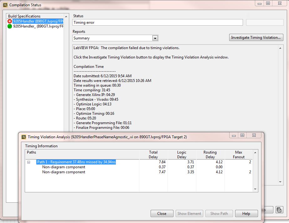
FPGA: update w / 14,4, fails w / Vivado 2013.4
My FPGA code that compiled fine in LV 2011, then 2013 LV (using Xilinx 14.4). I didn't contact for some time...
The upgrade to SP1 2014 LV, I believe that I have to re - compile to get the bit file to run on the target of the cRIO. However, now it does not compile. Cloud compiler error of timing. Clouds (local and compiler and elsewhere) report using Vivado 2013.4
The code handles a moudle of analog input of series C 9205. 6 of the 32 channels are run by a calculation of RMS. A time loop is set to do this each 185 uSec (9205 card channels = minimum update 4uSec * 32 channels = 128uS = maximum theoretical to run the FPGA and to obtain valid data). Each value of 650 samples a new RMS is calculated.
The rest of the channels get on average, 8 samples are averaged every 100th iteration of the loop above.
The timing of the loop is a front panel control. I tried this increasing by 185 to 200 uSec, but it does not help. All inputs and outputs to the FPGA VI are written in / reading of the *(cRIO-9068) of host real time be using the controls on the front panel.
This code has not changed in a very long time. I could share it if it helps.
My questions around the investigate Center window timing results. Here, nothing seems useful. What is "path 1' and how is it related to the block diagram? View items and path are inhibited. I have tried to change the build - optimize the performance and optimize for area etc... but the compilation always fails.
I will create a ticket with NEITHER. But thought pehaps someone here might have additional guidance.
For applications using hybrid...
(1) update install to 14.5 CompactRIO: C Series Module Support 14.6
(2) change of generation to optimize performance
-
Aggreagation Labview on 3s or 10 min
Hi forum,
I use a NI9220 with 100ks/s/ch so you can track where I am calculating the RMS values THD of a wave of current and votlage with Fr. and thd live. I woulde wishes to implement an aggreagation 3S and 10 minutes and write the values to file whenever the average is calculateted.
Is it possible to do this in labview with the example of moving average mabye?
Thank you
Martin
Hello
you set up the blocks to simulate to produce as many data points you want per second, then you add a timing loop to run every seconds.
http://www.NI.com/white-paper/4120/en/
Concerning
René
-
How to determine the maximum temperature in a row of 2 minutes?
I make the following request:
(1) temperature signal reads in all the 1 second, set in a while loop;
(2) I want to assure you that in a consecutive 2 minute, the temperature value is always less than a value, say 10 degree C;
(3) if she can meet the test, returns the value true, otherwise, continue to follow until it is true.
Possible ways to define a 1 d array with 120 elements, but I would like to know if there is a more elegant way? I can't put the table in a Subvi, when it is destroyed once the Subvi is left. LabVIEW edition offers the function of calculation of "RMS" (everything is in a under VI) and I do not have the function used in this VI.
If I understand the message of openness he wants to just wait that temperature is less than a threshold for at least 2 minutes, then exit?
Something like this should do if that's the case.

-
RLC, AC single frequency analysis results do not match hands calculated results.
On a single RLC monofrequency simulation analysis AC, the amplitudes resulting are off by a factor of 10. Phase angle values are all correct and correspond to the calculated values. On another example developed in a text book, same results. What I am doing wrong? In addition, how you change the ca of RMS to peak source or vice versa? Thank you.
-
RMS measurement over time "long".
Hello
I want to measure the RMS of 'complex' waveforme, so it is quite difficult to calculate from the graph. I use a power - gauge. My proplem is that the result is digitally displayed and the result changes from time to time. the signal is periodic with a time - period of 112ms. is there a way to graphically display the RMS?
THX
Hello stenzer,
I don't know I understood exactly what you want to do, but I think that the functionality you need is the "postprocessor. With this function, you can perform calculations on the results of simulation and display them graphically. You will find the postprocessor in the simulation menu > postprocessor.
-
How to calculate the overall RMS of a linear spectrum?
It is a calculation of post data capture, so it should be no big deal, but I can't do things. I have a linear spectrum of the 16 250 line. I want the overall RMS so that the frequencies. This means take each value of y for each point and square it. Add up all these square point values and then take the square root of the sum. It's this RMS spectrum. There are ways to do it in time galore. I guess I need to do with a point to point vi and the node of the formula.
Kind regards
Ron
Thank you. I wanted to try this vi but could not find it.
Kind regards
Ron
-
Measure cc using BasicDC-RMS and AvgDCRMS
Hello
I intend to calculate the continuous component of a noisy signal. Both the BasicDC-RMS and AvgDCRMS vi will give it the output under the waveform but how to get them as a constant instead of show with the waveform. The domain controller is component of the signal obtained will be used for the calculation later with a formula.
Thanks in advance.
Use Mean.vi of mathematics > probability & statistics palette on the component Y of the waveform.
Lynn
Maybe you are looking for
-
How to start the Library/bookmarks only window?
Older versions of FF had a command line option in the style of a 'b' after another character. In this case, I could edit and export bookmarks without having to start the main program with all its plug-ins.
-
Pavilion 23-q070se: long three and four beeps when I turned on my pc
As the subject says, my PC (Pavilion all-in-one 23-q070se, with 10 Win Home updated) three long beep and four short and repeated this model for some time (maybe 5 times), when I turned it on. But after that, he has worked - at least I didn't say anyt
-
The CLI for GS724Tv3 user manual?
Is there a reference CLI available for download somewhere for the series switches GS724T? (great forum BTW here, very useful so far!) Micky
-
Problem with the ASD file type
I discovered an important document was recovered by WORD, but when I tried to open, he was informed that it is an ASD file. Windows directed me to a site that contains a list of FREE downloads of software designed for ASD Files "difficulty and open."
-
Tengo PLOTS one y no PUEDO bajarlas. El error da're el 80246008. El Comando "incio del Fondo Inteligente (bits) transfer service" me ha notice. No if Se Ahí Todo el Problema eStara. What puedo HACER?. Saludos.