Calculation of signal to noise ratio
Hello.
I was wondering if it was possible to calculate the SNR of a signal with LabView? I use a DAQ hardware and an accelometer to measure a force.
Is that being said, possible to calculate SNR by looking at the graph of spectrum or vague? When there is no g on the accelerometer, there is a signal with a little noise... and I can see that in the spectrum of frequecny all the way to the cut-off frequency. What is the background noise?
I'd appreciate any help!
Thank you!!
Abraham_E,
Thanks for the data. Curiously, the data do not seem to care what language you were using when you got it.
The first data column appears as timing information. The dt in who is 0.0005, which corresponds to a frequency of 2 kHz. You said 400 Hz in one of your messages. The discussion at the point 2 below corresponds to a frequency of 2 kHz sampling.
1. you are right that SINAD is not very useful. SINAD assumes that all the power of the signal is the dominant frequency component that is not quite true for ECG.
2. the size of the FFT of the signal shows the dominant signals at 50 and 100 Hz which is likely to be able to line with frequency. Al here also erase lines 200 and 250 Hz. You certainly do not want to calculate SNR under the assumption that the desired signal is 50 Hz. The SINAD VI calculates the fundamental frequency than 49,97 Hz.
3. If you don't know the 50 Hz and harmonic components, there is no obvious lines in the spectrum remaining. I interpret this means you have the significant variation of heart rate data. This means that the heart rate is modulated in frequency. Frequency modulation broadens the spectrum.
4. because there is not predominant in the spectrum, it is unlikely that frequency domain techniques will be worth any in the determination of the SNR.
So, what can you do? Looking at the data graphic, I think a peak signal to noise power ratio could be significant. There are little noise, even at spikes, if it has a few problems too. I have divided the data set in 1 second segments. For heart rate in these data, each segment contains one or two beats. In each segment, I found the maximum and minimum values. I set the value from Ridge to Ridge for the segment of the difference. I also calculated the RMS value for the entire segment. Then the SNR is the signal from Ridge to Ridge divided by the RMS value. It is probably more accurate to use the RMS value of the QRS and exclude parts QRS of the RMS of noise, but to do both is algorithmically and by the much more difficult calculation. It would be also better force segments contain exactly one beat of each. Again, it is much more complicated. I then calculated the average of the SNR segment values and call it mean SNR.
As I pointed out, there are some problems with the definition (peak to peak/RMS). If you just want to compare signals within your lab to see which improves things, this should be good. If you want to publish data and compare to other published results, you have to find how they define and measure SNR.
In the attached VI I read the file once and recorded values in an array as a default value. Then I removed the file played screws and just worked with the data. To try this with other data simply insert read VI file in the appropriate place.
Lynn
Tags: NI Software
Similar Questions
-
NEITHER USB-6211 signal to noise
While using the analog inputs of the device USB-6211 (Labview 8.5 / Win 7) signal become noisier. By surprise, I got a signal perfect after you have disconnected and reconnected the USB card to the system. This behavior is reproducible for the cards (n = 4) that we use in our laboratory. Is this a known issue with the 6211 card and if so is there a method to reset the map using labview?
Thank you!
Christian
Christian,
I'm glad that you have solved your problem. Manuals for most of the DAQ cards NOR recommend resistance of two entries to HAVE to AI GND to ensure that a path suitable for polarization currents exist when it is used in differential mode.
Lynn
-
I have a card PCI-6255 that I intend to use for certain sensitive measures.
I'm trying to put together a budget-to-end error and I have a few questions.
My model is in terms of number of analog-to-digital converter (also known as the LSB in your datasheet).
In the table of absolute precision on page 5 of the 615 x standard OR I see a column called random noise, (uVrms).
I think I understand the residual gain error, offset error residual and associated with it and the INL error, but random noise is confusing to me.
Here's why: on the +/-2V of type range, the random noise is 16 uV. On this beach, the resolution of the ADC is 6.1 uV so random noise is about 2.6LSB
If I look at the +/-5V Beach, I see a random noise of 140uV. On this beach, the resolution of the ADC is 305uV so random noise is well under a LSB.
Therefore, in the budget of my mistake, I can use "1 LSB" for noise random when on the beach of 5V, but I have to use LSB '2.6' or '3' when the type 2V range.
I expect a signal of about 150 mV riding on a 2, 5V CC. I was worried, I might need to compensate the signal (remove the 2, 5V dc) in order to use the +/-gamme.2 volts to get the best resolution. Also, I thought that I would get better sound performance too. In looking at the figures here, but looks like I'd be better off using the +/-5V range (assuming that there is enough resolution) because the readings have less noise counties (even if it's more noise volts).
I can explain the error of Gain and Offset error by injecting known signals and making a "correction of the software. Not sure, but I think I can correct for the INL also if I use a 2nd or 3rd order polynomial. It is the random noise, I have problems understanding.
Here's the question: what is the random noise in table AI accuracy for 625 x boards? Can you give an example of how NEITHER could have measured it?
Secondly, note 2 says "sensitivity is the smallest voltage change this canbe found. It is a function of the noise. "He measured with a signal to noise ratio of '1' or '2' or some other standard, or is it a calculated value?
Thank you
MG
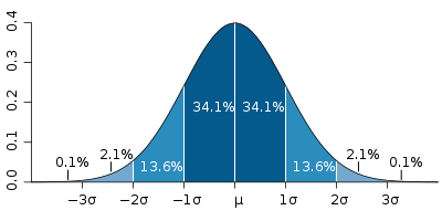
The function of Gaussian Distribution is often used to describe the noise. Random noise spec'd in the table of precision is a gap type distribution of probability of noise and was probably calculated using statistical analysis. That's why the uncertainty of noise takes into account a 3 coverage factor that represents the largest part of the distribution.


With respect, the specification of sensitivity, this requires a more detailed explanation, but it is essentially an industrial standard that takes into account more statistical analysis on a signal when awarded with noise. According to me, the mix is a compoenent of this measure.
-
What NI DAQ device or system can receive signals nanovolts?
We have an analog sensor here that its production gives us nanovolts control signal. I was wondering is there any device NI DAQ, you could introduce me so that I can take these steps for the Labview? (signal to noise ratio is low) It would be great if you also offer me an Osciloscope code or software in Labview that get the signal of the DAQ hardware and I can play with, or record the signal as a real Osclloscope because I couldn't find a good in the examples. If this question is not linked here please provide a link for me to remove this item and it ask for more in the forume somewehere. Thank you
nV is not much
 so some requirements more are needed:
need resolution?
need for precision?
bandwidth of the signal?
the source impedance (or current bias data acquisition acceptable entry?)
Value of Absolut or changes in the amplitude? (important for the specification of the drift)
I would go with a preamplifier or ask Keithley
 NI sorry
A good source of information to measure really tiny values is the "low level measurements Handbook" of keithley...
Sorry, no link to it... These % $§ ' engine % of research do not provide direct plus links

-
Average implement properly sampling frequency
I am writing a program for the acquisition of data that reads the voltage and data current with a 3 phase generator, IE. There are 3 channels of voltage and data 3 (also represented under tension) current data channels come in my USB-6009.
The waveform is not yet known but probably roughly sinusoidal until about a power of say 1.5 kHz frequency. I need to work on the (reliable) frequency in real time I know the speed of the generator. I use the 'harmonic distortion Analyzer' VI do basically this deep down it's a FFT on the data. I suspect it's too much an overload of treatment because if I increase to more than 1000 Hz sampling frequency, I'm starting to have problems - and if the data max 1,5 KHz I need to sample and analyze at least 3 kHz, of course.
Yes - the question is, how can I get the sample to say 3-5 kHz and work on the fundamental frequency of a channel in real time without causing any fall?
All responses are greatly appreciated.
Dave
Dave,
(1) I prefer to put all of the analyses (as TFF) in a separate loop. The loop of the acquisition is acquisition. He acquires the data and puts it into a queue or motor of action to be used elsewhere. In this way the acquisition schedule is not dependent on the time required for analysis or display or save to file...
(2) lines are built in features that allow the data to be passed to independent parties to the program efficiently and without risk of conditions of competition inherent in global or local variables. They also have interesting features like the clusters of the error and wait times. Motor action are the screws in the form of a while loop with a shift register uninitialized to retain this data. They contain generally structure case to allow the selection of different actions, such as Initialize, writing and reading, or more complex things like subset of return or average accumulate data. Research on the Forum for the nugget of Ben and many other messages on the subject.
(3) convert the data type as a whole. Obviously, you cannot acquire a fraction of a sample, by using a representation of data that supports the fractions is not necessary. In this case, it is not a big deal, but constraint points can tell you that LV is doing additional work behind the scenes to change data types, maybe not the way you wanted changed them.
(4) Yes and no. The FFT should work even if the signal to noise ratio is reduced. Think of the component continues as being the 'noise' in this calculation. If you want zero crossings, so it is essential that the offset be withdrawn. With the current shift zero crossings will be moved off the middle of the sine wave points or the signal may cross any zero if the oofset is greater than the peak of the periodic component value.
(5) I suspected something like that. Multiplying is a bit faster than dividing so it is best if the speed is important. If it is more convenient for the user or the programmer to get dividers, let the programme calculate the reciprocal multipliers. Do it once, outside the loop where it does not affect the time.
(6) I missed that you move data between the loops. Can't do it with the register shift. See point 2) on the queues or the drivers of the Action. Notifier could be used also for the stop. My opinion: the only place where you need a local variable is if you need to write a value to a control, such that when you set a saved a file configuration.
A lot to learn.
Another question: in the original post you said that you needed the determination of the frequency in 'real time '. It is a slippery term. You use it for anything other than the number of samples to read? How fast can change the frequency? What are the consequences of a delay in obtaining the frequency? How late can tolerate you before that consequences are unacceptable?
Lynn
-
Haven't seen no debate yet, but it seems to me that the new 4 k 480 codec is perhaps the most exciting aspect of the latest announcements. Compressed 4 k with a minimal flow of manageable data and artifacts.
Are Peter et al, we able to obtain the specific sheet about the codec again? 4:2:2 is a given, but is this always just 10-bit, or will it be 12 bit? (Pretty please, please!)
Also, is it possible to see a similar to 2 k recording update? 12 bit 4:4:4 XAVC in 2 k would be extremely useful.
All,
XAVC Class300 is the current implementation of the XAVC 10 bit 422 in the F5, F55 cameras. We are able to implement the Class480 upwards to 30 p because it is still within the bandwidth, threshold of the existing SxS card shape for sustained flow write speeds.
As a benchmark, the Class300 is 300Mbps to 30 p. And the class 480 480 Mbit/s to 30 p. It is simply mount the data rate, and with a little better PSNR - Peak Signal to Noise Ratio - the two classes are in the implementation of the XAVC 10 bit 422
As you may know, XAVC is the implementation of Sony of H.264, to very high quality @Level 5.2. The architecture of coding is process each image based on the characteristics of unique photo. In other words, the camera is independently encoding each image based on information from complex frame-by-frame. It's very different from codecs of competitor in the competitor cameras in which they define the different coding to the first frame only and do not change during the writing of this file.
If you really want to see a difference in image quality between the existing Class300 and the Class480 what you photograph, much will depend on the level of complexity in each frame.
Several workflow of third party suppliers are already supported including Resolve and Adobe Class480. If you look in their XAVC settings you will see listed.
Concerning
Peter
-
Indexing of a table with multiple indexes
Hi all
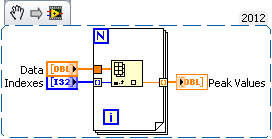
I just used the detector of Ridge VI on table 1 d with a threshold. I now have an array of index I need to round to use as a real index. My question is, with this index corresponding to the points picture, how, I take the peak values
To give a bit of context:
1. I have three time correlated signals. I filter them, normalize, then add them so that I can increase the signal-to-noise ratio.
2 pic DetectionVI gives me a table where are these pics
3. I want my end result
A. Signal1 [peak_indices]
B. Signal2 [peak_indices]
C.Signal3 [peak_indices]
Now I think about it in the way I have d code in MATLAB which is much easier, but I would like to do this in Labview and would be very happy to any idea.
Thank you
-Joe
As you said, once you have rounded tip to the nearest value locations you have an array of markings. From there on, it should be a simple matter of passing this table in a for loop that auto-index of the results that you went out to generate a table of peak values.
-
Want to use Lock-in detection with a linear detector with diode bars
Hi people,
I work with OR lock virtual amplifier to build a detection system that uses a linear led strips detector to measure the effect of an electric field on the spectrum of a molecule absorption. Traditionally, this technique was carried out using a single photodiode detector connected to an external amplifier of detent and the absorption spectrum was analyzed using a spectrometer. The lock would demodulate the signal of interest based on the wavelength. In my setup, I acquire any range (all wavelengths) simultaneously to speed up the experience and improve S:N. to do this, I use a spectrometer OOptics USB2000 + and NI virtual LIA. Each element of the photodiode array, then acts as a unique photodector calibrated to a specific wavelength. I want to demodulate the signal of interest of each element of the matrix of the photodiode.
After reviewing several of the messages on this forum, I start to worry if my setup actually work. So far, I have seen that everyone uses a detector single channel connected to a card scanner of some sort, which also acquires a reference signal. Phase delays would come mainly from electronics and cable lengths. In my setup, the detector is digitized by the 2 MHz ADC in the spectrometer OOptics and my digitizer OR is only to measure the experience reference signal. Because two ADC of separate instruments are used, this prevents the use of the vLIA? My intuition tells me that don't know, but I am relatively new to the use of detectors photodiode array for this purpose.
Any help would be greatly appreciated.
Timchem
Tim,
Now we are getting somewhere.
The effective sampling rate is about 70 Hz. Unfortunately, the time is probably metered software, which introduces additional jitter at the time of each data set. Sampling a signal to the Nyquist rate only gets you the minimum information on this signal and certainly produced very little significant phase information.
Given that the intensities of the pixels are measured at the same time, you have no worries for the phase shifts between the pixels.
Question about the synchronization: the spec introduces a measure whenever it receives a TTL pulse? Integration of 1 ms, then send 2048 data points, then wait for the next pulse? Assuming that's what he does, then you have a chance to lock a verrrrrry slooooow amplifier.
It would work something like this. Setting the sync generator to produce a measure trigger pulse every ms T, where T > 13 + 1 ms. Suppose that T = 20 ms (FLA = 50 Hz) to keep simple mathematics. Sets the modulating frequency to 1 Hz. Then you get 50 samples per period of modulation, or sample all 7.2 degrees.
Now I need more. You indicate that your alternative signal is microvolts. What is the significance of the component continues? The relationship between these two signals is the signal to noise ratio. A quick glance on Ocean Optics web site indicates that dynamic range for a single purchase is 1300: 1, which seems low for a device with a 16-bit A/D converter. This must be the limit of the photodiodes to an integration time specified. If the signal is really limited to this range, you can get into trouble. The lock-in amplifier depends on some signals actually being there, just smaller than the noise. In this case the limitations of photodiodes or the processes scanning spectrometer, it is possible that there are really no signal there to extract.
If your signal is a quantity equivalent to 10% of the dark current, you must get a signal you could accurately measure on average for about 100 cycles of the modulation frequency (1 Hz) to start. Your samples are stable for 2 minutes or more?
A different instrument may be the best bet.
Lynn
-
W520 bad sound quality glitches and audio with current conexant driver
Hi guys,.
I have to deal with several audio problems. Before any change, I had a lot of glitches audio during playback of MP3s, videos etc.. Playback of the sound crashes from time to time and gives me the error of his (seeds, where some samples are played repeatedly).
Then I read that the withdrawal of the conexant driver and using the windows 7 drivers works better. And they did it. I uninstalled the drivers conexant and tradingtextile.com win7 installed some standard drivers. Then, almost all the errors and faults were gone. But I could not use my docking station anymore.

OK, now, I have installed the latest drivers conexant for windows 7, the problem is less than with the old drivers conexant, but always worse than drivers of windows 7 from microsoft.
These problems appear to be associated with the use of the network. I think they appear much more often, if I'm connected to my local network or surf the internet. This occurs when you are using LAN or WLAN.
In addition, the signal to noise ratio is very poor. If I kinda wrecked my speakers there are several 'sounds' when you use the W520, internet access, access hd etc. can all be 'heard '...
Everyone knows the same? I spent a lot of time working on this problem. Why the lenovo could not put a decent sound card in the W520? It really gets me upset. Any help is appreciated.
See you soon,.
Marcus
-
Get the right order of tones for DTMF decoder
I'm trying to decoder stream DTMF signal (contains mutiple tones, delay, noise), however, I have the problem to separate each tone of the stream signal in order to enter the Goertzel for later analysis.
The phone number is 534-343-3436. To the decoder input, I don't know what's the phone number again. However, I want to separate 5 then 3 then 4 then 3... your if I put analysis individual tone is what key corresponding to this phone number.
Anyway I can archieve in LabView?
There should always be an interval of no signal between pairs of tone - if not, you can not detect repeating values. For phone number 534-343-3333 you can not just look for a frequency change. Your signaling protocol must specify the minimum length of a pair of tone to be considered a valid signal and a minimum without your being a separation valid between the numbers. Maximum number of hours is useful, but not as important, except to determine how long the system will wait for a valid number. Time settings may depend on the acceptable minimum signal to noise ratio.
The algorithm would be something like this: amplitude discrimination allows to find gaps between pairs of tone. There is no need to be too good - just find approximate segments. It will use timing specifications for set time periods to consider. Within each segment threshold use the FFT to identify the pair of tone. You can also use a FFT on the gap segments to check that they do not contain a pair of tone.
Also consider various errors. On tampons in your Western Electric simultaneously pressing two or more keys in a row or a column results in a single tone. I have not watched the DTMF generators for a few years so I don't know how how some of the IC-based generators to handle this situation.
Lynn
-
How LV can determine a mean value of 10 photos?
Hello together,
I would like to identify a picture of the average value. Because the signal-to-noise ratio is high. So I get a picture (see attachment "Original_Picture.png") 10 times (for loop) and you want to calculate the 10 images at frame 1 of value average. I tried with the operator Imaq MulDiv Image processing (see attachment 'Example.PNG'). Unfortunately the 1 image of the average value (see attachment "Result_Image.png") is not what I need.
I hope someone can help me.
Thank you
zapfle
zapfle wrote:
Hi Andrey,
Thanks for the reply. I tried your VI (see attachment), but unfortunately it does not work. I think that the images will be added, but not divided. Do you not see my error?
Greetings
zapfle
It seems that you have overflow. If your images are U8 (8 bit gray levels), then accumulation buffer must be at least I16 (or SGL).
Another point - you can have the condition of competition caused by the IMAQ dispose at the end take note that images can theoretically be eliminated before posting, then you will see nothing at the end.
Andrey.
-
Mitigation of the line of WAG54G2
How can I find information about WAG54G2 - SN margin, noise margin, mitigation of the line, Signal-to-Noise Ratio (SNR)?
Try this link... .to SN margin, noise margin, Signal - Noise Ratio (SNR)
-
Voice over recording change vs multitrack view
Hi guys, need some advice here.
I always taped voice-over in editing with Audition 3.0 (Windows 7 64-bit)
Recently, I bought a Creative sound card (X - Fi Titanium HD) that sounds good and that records 24 / 96 kHz with excellent results using several different microphones, mainly an EV RE20.
I have the main of my mixer left and right coming out using cables of 1/4 inch outputs and enter the audio card to the left and right inputs via RCA...
In the audio hardware setup Auditions change the display, there is only a choice either to the left or right to the but not a mixture of the two as a starter. (aid to the left)
Do not use the input on the card because I wanted to use the ins RCA (left/right) on the sound card and microphone input is a 1/8 input that would require another Y microphone cable 1/4 to 1/8 and the fact that I had issues with 1/8 entries before.
Then, when I record the voiceover in the edit mode, I think I'm really only half of the signal (to the left) which means that I need to gain preamp more that I would get a good level.
Recently, I have been recording in multitrack view using the 1-way left and right track 2 at the and then doing a mono mix that translates into a very pleasant without level to increase the gain a lot.
So I guess my questions would be I'm actually saving half the signal change their view by simply using the left
and if that's true, I just have to continue recording in multitrack view using the configuration I described above.
Any advice would be greatly appreciated.
It's just a signal level - you actually lose anything. You can't actually say it is 'half' a signal - it is just a signal at a different level. And you can always get the audition level without loss by record or convert your signal in 32 bits (native format of the hearing) to floating point and it normalize to the level of what you want. When you have only a mono microphone - a track is all you need, there is absolutely no benefit to the recording of two tracks. As to how you save (MV or EV), well it is entirely up to you – that really suits you. The only notable difference is that EV record in a temporary file to be saved in a permanent file later and MV went directly to a file.
Do you use a microphone preamp with your microphone if you use the entries in the? If you're not, you don't get something like the good structure with the card, such as a microphone does not what whether as enough signal to drive an entry to the correctly. It is a hardware problem, and not one that you can correct for with software, because it will significantly change the signal to noise ratio.
-
How to calculate the signal / noise from the graph?
In my current project, I read a periphera voltage signal. the signal lead noise even after filtering. So, to identify the necessary data, I averaged the signal.
I have attached the file with an image of graphics. In this graph, the recorded data are drawn black and medium online graph is plotted in red. Now, I have to calculate the ratio of signal to noise to specify with these peak values. How to do?
As the signal passes through zero, be careful in the way you set the signal / noise. For sinusoidal signals, that ratio is defined as the RMS value of the noise (the signal with the desired sinusoidal signal deleted) divided by the effective value of sinusoidal component.
First of all I would like to subtract the average value of the raw signal. The difference is the noise. You can set the signal / noise. A RMS calculation might work. If you have a mathematical model for the desired signal, a fitting for this model can be useful too.
Lynn
-
The intensity of the signal - dBm calculation?
Values returned signal strength by WSN nodes seem to range from 0 to 100. How are these calculated values signal strength? Along with power and sensitivity of output are listed as + 17dBm and - 102dBm respectively, this is a theoretical difference of 119dBm. The values of the signal strength can be correlated to dBm?
Thank you!
Garrett
Hi Garrett.
The radio returns to the quality of the relationship between 0 and 255. Currently, we have 39 dB representing 100% and-97 dB link quality, representing 10% quality of the connection. Note that these values may change in the future.
Maybe you are looking for
-
ElitePad 900: 900 Elite will recognize is no longer keyboard Bluetooth after Windows update 8.1
I have a HP Slim Bluetooth keyboard (product No - H4Q44AA #AB) tht, I was pairing with my HP Elite 900 with much success until I did an upgrade to Windows 8. 1. now I can not use the keyboard wireless at all. I even tried to use a different wireless
-
3024 can connect and new servers
We bought a Powerconnect 3024 switch, years before I started and we are again moving servers with a new internal IP address range. Will I need to configure the Powerconnect switch to the new range as well, or will it continue to work.
-
site-to-site and browsing the internet
Hello I have a simple question. We have to buy two asa5000 devices and connect them via the fixed site-to-site tunnel. One side will use the ADSL modem in Bridge mode. My plan is to use PPPoE auth on port wan asa. In addition, it is important allow u
-
Orphaned comments VmWare Workstation
I am using Vm Workstation 7.1.3 build-324285. My host OS is Windows Vista Business 64-bit. I scheduled the start of a Guest VmWorkstation using the command as follows:At 06:00 "C:\Users\Kirk\vm_win_xp_pro.bat" the bat file contains:****************
-
Edge .oam file is not correctly displayed in the DPS.
Here's the scenario. I have an animation I created for an article of DPS (Digital Publishing Suite) but it does not display correctly and I can't understand why. It displays is too large and goes past it's bounding box or it displays too little.Art