calibration grid
Hello
I use NI Vision (917 x 918) calibration grid, but my image, I want to calibrate is 1920 x 1080. How can I get this working or is this even possible?
Thank you
As Bruce said, the whole point of the calibration of the grid is to calculate the "optical imperfections" of your system (camera + lens) If you take a photo with your imperfect optical syytem for a grid of almost perfect to be able to estimate the optical distortion you "camera + lens".
See this:
Tags: NI Hardware
Similar Questions
-
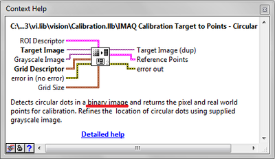
Calibration target of error to points - circular points
Hello
Here's my VI where I want to use the function calibration target circular points points to start my calibration.
This function seems to be quiet, easy, and yet I came to an error which I can't get rid of. I think that there is nothing wrong with the image I want to, but you never know if you can find this image in attachments.
Kind regards
Ruts
Hello
you need to the threshold calibration grid image in order to extract the coordinates of the circles.
Take a look at the example of "Calibration of Perspective" in aid of Labview-> examples.
In addition, reading the detailed information of the features you use will help also:
Best regards
K
-
"An insufficient number of calibration points function" in the calibration to learn?
I suspect that IMAQ learning model calibration VI can be tapped, like I can't make it work for the few reference points.
I get error-1074396116, even when I'm passing over 4 points of reference, as specified using.
I noticed these posts, the http://forums.ni.com/ni/board/message?board.id=200&requireLogin=False&thread.id=10257, the http://forums.ni.com/ni/board/message?board.id=200&message.id=17400&requireLogin=False, where the problem seems solved. The VI of the sample provided by the first poster, http://forums.ni.com/ni/attachments/ni/200/10279/1/Reference_Points1.vi, does not work for me either.
My setup is LV9 on winXp32, image of 640 x 480 8-bit grayscale. What I try to do is not the subject of the post, the potential bug is.
Can anyone provide a working example? Calibration samples included in the finder of the example use calibration grids, not of few reference points AFAIU.
Thanks in advance, Enrico
After a little experimentation with the VI provided by the first poster (attached my small change), I realize account of the calibration point of view seem to need a minimum of 5 points, while non-linear required a minimum of 9. So, there is a bug in the documentation. This can be confirmed?
Thank you, Enrico
-
Hi all!
In LV 8.6, there is an example: non-linear calibration Example.vi (coins). I would do the same thing in the Vision Assistant.
First of all, I find and load the calibration grid, created a non-linear model
Open the image piece, and when I select: Calibration of the image, this message appears:
"The selected file contains no valid calibration information.Could someone help me?
Can you post the vi as well?
-
Why my corrected image has non-uniform scaling (mm/pixel)?
I use Vision tools of OR to calibrate nonlinear distortions by imaging a calibration of the spoaced points unfirmly image. I have spread this information of calibration to calibrate a series of images taken under the same conditions as my calibration grid. Then, I need to correct these images before I can make dimensional measurements. (Due to the nature of the processing routine measurement I need that these images corrected first). I also need to enter the actual conversion to the images corrected to this measure of processing routine. I get this by using the Pixel convert to real World.vi for each pixel in the image in order to see any variability within the image. I suppose this conversion value is consistent thoughout the picture but it isn't and ranges from 10%.
Can anyone help explain what might happen?
Secondly, in the correction of my images I only have the interpolation methods: zero order and bilinear. Quadratic and cubic splines are grayed out. Not sure why this is?
Thank you
Dan
Another detail - calibration results NOR are valid within the calibration grid. The numbers get anywhere outside the grid. They get also a little wacky on the borders between the boxes.
Loop through each pixel is a way to do it, but it is slow. The only other possible approach I can think of is to map the image to a corrected image. You can see distortions in this way, but you wouldn't have measurements for them. I might consider to check every pixel on the other, given that the scale factors are not changing too quickly.
Bruce
-
Help on Perspective correction, Image stitching and then pattern matching.
Hi all
As a newbie in LabVIEW, I don't know a lot about machine vision.
I need for my project automation, stitching the images (from 4 cameras, 90 degrees). Do the perspective correction and then form a label (which is actually pasted on the jar).
Please share your experience on the same type of project. And help me to proceed with the development of the project.
Also find enclosed all the pictures from the camera.
PS: Due to budgetary constraints, I use very basic USB cameras available, and the attached picture is the actual image.
To be able to correct the image for distortion, you first have to calibrate it. Assuming that your setting of the camera is constant (i.e. the bottle always at the same place in what concerns the cameras, I would first of all paste a grid around the bottle calibration and then take a few pictures of this grid with all four cameras.)
We install a calibration grid, you can print: C:\Program Files (x 86) \National Instruments\Vision\Documentation\CalibrationGrid.pdf
This example will then show how you can learn the calibration using the images of the grid, and then the correct images would have taken you without the grid.
\LabVIEW 2010\examples\Vision\2. Calibration Example.llb\Nonlinear Calibration Example.vi Functions\Calibration\Nonlinear Note that you need to recalibrate the system if something changes (lens focus, camera or bottle of position.
After this step, you should have 4 images 'straight' which have been corrected for distortion and which can be used for sewing.
For sewing, unfortunately, Vision Development Module does not include an exit of the seams of box function.
If this is acceptable, you can use some third party software that provide features couture, such as Photoshop Autostitch, Hugin, Ptgui, Panorama Tools, search for Microsoft Image Composite Editor, CleVR Stitcher or Adobe Systems.
If you need to do everything in LabVIEW, I can point you to some of the tools provided with the library you can use to create your own algorithm of seam. This part is certainly the most difficult of your project.
Image stitching process can be divided into three major components - image calibration, registration and fusion. We already talked about calibration.
-Image recording is to couple features in your images in order to align them. You can use tools like the corresponding model and edge detection for this purpose Watch examples of vision LabVIEW to know how to code in LabVIEW.
-Image mix is to process the images to account for the difference in brightness of images from several cameras.
Histogram analysis on the different images and applying a lookup table are simple tools that you can use for this purpose.
Images can then mingle with features like IMAQ ImageToImage.
This thread also talks about sewing:
http://forums.NI.com/T5/machine-vision/image-stitching/m-p/860414
Hope this help get you started. Good luck with your project.
-Christophe
-
VBAI 2012 "save the image calibrated to the file" issue
Hello
Under the State of 'Calibrate Image', 'Save the image calibrated to the file' option does not work correctly.
With the exception of the type 'Point of Distance' of the calibration, the new image is ever recorded. I checked the calibration image .cal2 in the folder \ProgramData\National Instruments\Vision AI\Calibration Builder, each iteration the meta-data are updated but not the image.
I have a camera calibrated with a grid (see picture) and using the model of the distortion. Working remotely can sometimes change and I need to take a recalibration. This step should be as simple as possible. Example: put a model calibration in the field of view, then press a button recalibrate.
The problem mentioned above, it is impossible. Whenever I have to manually go into the choice of the State of the Image calibrate and update the calibration image myself. Otherwise, calibration is recalculated from the original image which is not best suited for the new working distance.
Is there an easy way to make VBAI save a new image of calibration with each iteration?
Or is it something that I did not understand this option 'save image calibrated to the file?
Vision Builder for Automated Inspection VBAI 2012
Windows 7 64 bit
Best,
Ken
Hi Larpin,
Unfortunately VBAI does not support the suggested behavior. The best solution in my opinion would be to implement your application completely in LabVIEW!
To Eval download link. Version:
https://lumen.NI.com/nicif/en/evallv/content.XHTML
Kind regards
MISIC
-
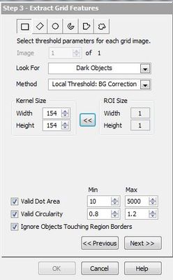
Using the thresholds the in Vision Assistant Image calibration
I would like to form images of calibration with some images of 1280 x 720 of grids that I take with a fisheye lens. Usually, when I raise Calibration training Vision Assistant interface, I have some tools really powerful local thresholding as in the screenshot above.
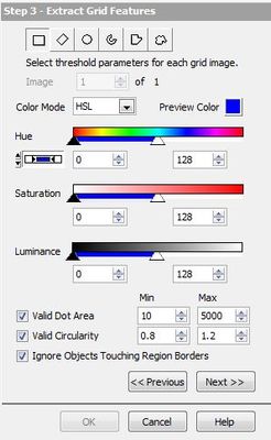
But with images that I put in now, I'm threshold options that aren't really my needs. These are shown in the screenshot below. Is it possible to manually choose the local threshold options?
Hello
You got this window because it seems that you have a 32 bit image instead of an image of grayscale 16 or 8-bit.
Convert your image into 8-bit, and you'll have the threshold parameters you need.
Hope this helps
Agress
-
Original location in a corrected image (using calibration data)
Hello
I use the tool of vision to correct the distortion in images.
I do not use the model grid point let the software generate the calibration sheet, but rather use a set of points (which I can define precisely in the distorted image) and provide their respective coordinates 'real world '. I can then apply this correction to other images.
So far so good.
Now I want to superimpose two sets of images, which are distorted differently (for example, they represent the same object, but were photographed in slightly different conditions). I have
good adjustable using the method above and the other separately, with its own separate correction, but I'm stuck there.
Each calibration/correction is characterized by a scale factor and a coordinate of origin. I need both to be able to superimpose the two sets of images.
I chose non-linear calibrations that preserves the area and I thought of a way to recover the scale factor by calculating the areas of all patterns square in my series of (as calculated in the original image) calibration points, taking the average, then the square root of the area average: This gives the spacing between the points equidistant in the corrected image.
However, I can't figure out how to get the original location in the corrected image. One of my points of calibration is associated with the position (0, 0) in the real world. However, it is neither its position (in pixel unit) in the original image or the corrected image. I need the latter. How can I get it simply (I can think of sophisticated ways to get it, but I suspect that it might be a trivial).Thanks in advance for your answer.
Sincerely,
X.Hello
I guess you are referring to "Convert to/from the real world" screws. As far as I understand well as do these screws, they refer only to two "spaces". One is the distorted image of origin (with coordinates in pixels) and the other is the ideal 'real world' space, where this image was generated, with coordinates expressed in all the units you choose. I am concerned about a 'third space', the corrected image generated by the Vi "IMAQ Image of calibrated" correct, and I want to know the point, which, in the real world, has the coordinates (0, 0), where in this picture (if possible with coordinates in fractional pixels, coordinated whole pixels not only).
I haven't posted my response to Nate, but basically we agreed that what I wanted was not available yet. I have work to do to get this information (as I suspected). It's a shame, because the Vi above obviously knows how to calculate what I'm looking for, because it maps the pixel (or fractional pixel coordinates) where the origin is located in the real world, on an another coordinate (fractional) pixel in the corrected image.
This may be available in a future release, but for now, some work is needed here...
X.
-
I have random grids across the screen of the computer.
Original title: alignment grid, help please!
For a random grid of right lines appeared on my computer. I recently got this desktop computer built as a gaming PC and now random computer grid lines appear on the screen of the entire computer. This isn't a background screen thing, no matter what I / open grid aligns show through everything. Even when I start my PC version lines appear on windows loading screen that the computer starts. I don't know how it happened, just randomly all of a sudden they arose and now I have no idea as how to get rid of them. He said loading the computer grid alignment, there is a menu but it closes within 2 seconds and I have no idea what to press. Help, please!
Hey there,
In fact, it turns out it was the screen itself. Personally, I don't think I've hit, but he could have just popped up by itself. I personally had a ve278h 27 "asus to blacklight led lcd monitor 2ms 1920 x 1080 hdmi d - sub spk. The way I solved my problem has been messing around with the buttons below the screen. For example according to which monitor you own must be you know your settings and other buttons that do other things with the monitor. My buttons were below the screen to the right, yours may vary. Anyway my monitor has an option S/A and I solved the problem by pressing a few times in a row. I noticed when I pressed that the alignment of the grid change really. So, try looking through the calibration of your screen and mix around a bit and let me know how you go! Another way, I knew it was my monitor was turning the monitor market. ID turn it off then on again and notice that the grid lines disappeared temporarily for a few seconds. -
4.0.3 export the result of grid in xlsx for different data type
Hello
Using SQL Dev 4.0.3.16 build 16.84 principal.
Windows 7
Java 1.7u80
Run the query, click with the right button on the result of the grid:
When you export data in xlsx format, why the numbers data type has different type of font.
-Number / digital-> dialogue

-date and varchar2-> Calibri


Step to reproduce:
1 run this query
Select 100 n, '100', to_date (1 January 2015 ',' DD-MM-YYYY "") as d
Double;
2. right click on the grid - export
3. choose the Format: excel 2003 + (xlsx)
Thank you.
Buntoro
This is a known behavior. And I think that there is a feature request to the SQL Developer Exchange, like the export of dates date request and not as text.
Concerning
Marcus
-
Dreamweaver CC fluid grid divs do not stretch to cover 100% of the screen
Hello
I do another sensible provision using DW CC and I came across a problem.
Design colored divs that spans the entire page to 100% with a background color and borders.
I already did the design upwards as a layout width fixed to get the color codes etc. and that works well, with colors that covers the screen.
Now, I'm putiing design in DW CC using checkerboard to fluid and there is a white border on the Web site.
I can't work on how to get rid of this. Here are excerpts from my two lots of CSS stylesheets, one for a presentation grid fixed and one for a structure reactive
CSS FIXED WIDTH
body, td, th {}
do-family: Calibri;
do-size: 14px;
Color: #000;
}
{body
left margin: 0px;
margin-top: 0px;
margin-right: 0px;
margin-bottom: 0px;
}
* / The wrapper header spans the entire screen no matter what size and does not have a white border on the left and the right
{#headerWrapper}
background-color: #000;
height: 101px;
Width: 100%;
margin-right: auto;
left margin: auto;
border-bottom-width: 2px;
border-bottom-style: solid;
border-bottom-color: #BDDB6D;
}
FLUID GRID CSS
The fluid layout grid CSS has the following in it:
{.fluid}
Clear: both;
left margin: 0;
Width: 100%;
float: left;
display: block;
}
{.fluidList}
list-style: none;
list-style-image: none;
margin: 0;
padding: 0;
}
/ * Mobile layout: 480px and below. */
{.gridContainer}
left margin: auto;
margin-right: auto;
Width: 86,45%;
padding-left: 2,275%;
padding-right: 2,275%;
Clear: none;
float: none;
}
{#div1}
}
* / This header wrapper extends through the presentation of the grid only and has a white border on the left and the right
{#headerWrapper}
Max-width: 100%;
height: 101px;
background-color: #000;
border-bottom-width: 2px;
border-bottom-style: solid;
border-bottom-color: #BDDB6D;
}
What do I need add to the fluid grid layout to make the headerWrapper div span the screen, no matter what width?
What should I put in the grid CSS transmissions so that he can do that?
Thanks in advance!
I did it! I can't believe. The code I used is followed. The bar divs set color and at the border through the entire page and the wrapper divs to contain content in the various bars across the page.
I must say that DW CC fluid grids are much more stable to work with and it can take a lot of coding by hand now. This is a great improvement on when I tried to use grids of fluid on a project last year.
IN THE SECTION MULTIMEDIA PHONE REQUEST
{.gridContainer}
left margin: auto;
margin-right: auto;
Width: 100%;
padding-left: 0;
padding-right: 0;
Clear: none;
float: none;
}
{#headerBar}
background-color: #000;
min-height: 101px;
border-bottom-width: 2px;
border-bottom-style: solid;
border-bottom-color: #BDDB6D;
padding-top: 2.735px;
}
{#headerWrapper}
Width: 86,45%;
padding-left: 2,275%;
padding-right: 2,275%;
Clear: none;
float: none;
left margin: auto;
}
{#menuAnimationBar}
background-color: #B7B7B7;
height: 293px;
border-bottom-width: 2px;
border-bottom-style: solid;
border-bottom-color: #BDDB6D;
background-image:-webkit-gradient (linear, 50.00% 0.00%, 50.00% 100.00%, color-stop (0%, rgba (153,153,153,1.00)), color-stop (100%, rgba (192,192,192,1.00)));
background-image:-webkit-linear-gradient(270deg,rgba(153,153,153,1.00) 0%,rgba(192,192,192,1.00) 100%);
background-image: linear-gradient (180deg, rgba (153,153,153,1.00) 0%,rgba(192,192,192,1.00) 100%);
display: none;
}
{#contentBar}
background-color: #F8FCF1;
min-height: 200px;
background-image:-webkit-gradient (linear, 50.00% 0.00%, 50.00% 100.00%, color-stop (0%, rgba (245,251,234,1.00)), color-stop (100%, rgba (251,253,247,1.00)));
background-image:-webkit-linear-gradient(270deg,rgba(245,251,234,1.00) 0%,rgba(251,253,247,1.00) 100%);
background-image: linear-gradient (180deg, rgba (245,251,234,1.00) 0%,rgba(251,253,247,1.00) 100%);
}
{#contentWrapper}
Width: 86,45%;
padding-left: 2,275%;
padding-right: 2,275%;
Clear: none;
float: none;
left margin: auto;
}
{#socialMediaBar}
background-color: #000;
min-height: 83px;
border-top-width: 2px;
border-bottom-width: 2px;
border-top-style: solid;
border-bottom-style: solid;
border-bottom-color: #BDDB6D;
border-bottom-color: #BDDB6D;
}
{#socialMediaWrapper}
color: #FFF;
Width: 86,45%;
padding-left: 2,275%;
padding-right: 2,275%;
Clear: none;
float: none;
left margin: auto;
padding-top: 2,275%;
}
{#footerBar}
color: #FFF;
background-color: #AAAAAA;
min-height: 176px;
background-image:-webkit-gradient (linear, 50.00% 0.00%, 50.00% 100.00%, color-stop (0%, rgba (153,153,153,1.00)), color-stop (100%, rgba (185,185,185,1.00)));
background-image:-webkit-linear-gradient(270deg,rgba(153,153,153,1.00) 0%,rgba(185,185,185,1.00) 100%);
background-image: linear-gradient (180deg, rgba (153,153,153,1.00) 0%,rgba(185,185,185,1.00) 100%);
}
{#footerWrapper}
Width: 86,45%;
padding-left: 2,275%;
padding-right: 2,275%;
Clear: none;
float: none;
left margin: auto;
}
IN THE MULTIMEDIA TABLET QUERY SECTION
{.gridContainer}
Width: 100%;
padding-left: 0%;
padding-right: 0%;
Clear: none;
float: none;
left margin: auto;
}
{#div1}
}
{#headerBar}
}
{#headerWrapper}
Width: 90.675%;
padding-left: 1.1625%;
padding-right: 1.1625%;
Clear: none;
float: none;
left margin: auto;
}
{#menuAnimationBar}
display: none;
}
{#contentBar}
}
{#contentWrapper}
Width: 90.675%;
padding-left: 1.1625%;
padding-right: 1.1625%;
Clear: none;
float: none;
left margin: auto;
}
{#socialMediaBar}
}
{#socialMediaWrapper}
Width: 90.675%;
padding-left: 1.1625%;
padding-right: 1.1625%;
Clear: none;
float: none;
left margin: auto;
}
{#footerBar}
}
{#footerWrapper}
Width: 90.675%;
padding-left: 1.1625%;
padding-right: 1.1625%;
Clear: none;
float: none;
left margin: auto;
}
{#menuAnimationWrapper}
}
IN THE PC MEDIA QUERY SECTION
{.gridContainer}
Width: 100%;
Max-width: 1920px;
padding-left: 0%;
padding-right: 0%;
margin: auto;
Clear: none;
float: none;
left margin: auto;
}
{#headerBar}
}
{#headerWrapper}
Width: 88.5%;
Max-width: 1232px;
padding-left: 0.75%;
padding-right: 0.75%;
margin: auto;
Clear: none;
float: none;
left margin: auto;
}
{#menuAnimationBar}
display: block;
}
{#contentBar}
}
{#contentWrapper}
Width: 88.5%;
Max-width: 1232px;
padding-left: 0.75%;
padding-right: 0.75%;
margin: auto;
Clear: none;
float: none;
left margin: auto;
}
{#socialMediaBar}
}
{#socialMediaWrapper}
Width: 88.5%;
Max-width: 1232px;
padding-left: 0.75%;
padding-right: 0.75%;
margin: auto;
Clear: none;
float: none;
left margin: auto;
}
{#footerBar}
}
{#footerWrapper}
Width: 88.5%;
Max-width: 1232px;
padding-left: 0.75%;
padding-right: 0.75%;
margin: auto;
Clear: none;
float: none;
left margin: auto;
}
{#menuAnimationWrapper}
Width: 88.5%;
height: 293px;
Max-width: 1232px;
padding-left: 0.75%;
padding-right: 0.75%;
margin: auto;
Clear: none;
float: none;
left margin: auto;
}
-
Grid toggle when you use vertical tools, LR 5.3
For after the video tutorials online for LR5, pressing [CTRL] + [ALT] + O when you use the vertical tools in the part of Correction of the lens design tools will toggle the Overlay network and outside. When the grid is displayed, the tutorials also show it would be a top/Center options toolbar that has calibration and transparency controls to customize its appearance. This key combination doesn't seem to work for me in LR5.3. Has it been modified, deleted, known, bug or I do something wrong? (LR 5.3, Win 7, 32 - bit)
I think you could talk about two different grids.
There is the auto-grille that lights up when you access any slider in the manual lens correction tab - it is transient and not definable by the user.
There is the magnifying glass which is consulted withi opinion collection grid > magnifying glass Overlay feature. So the key [CTRL] [ALT] [O] to work, you have to select a grid, Guides, or Image first to superimpose. Then, it works as expected. I suspect that if you turn on the grid by checking it in view > Loupe Overlay, it will work as expected.
-
How to align the position of a node in a pane of the grid using CSS?
Hello
I have an interface defined in FXML:
I want to align the labels to right using CSS:<?xml version="1.0" encoding="UTF-8"?> <?import java.lang.*?> <?import javafx.scene.*?> <?import javafx.scene.control.*?> <?import javafx.scene.layout.*?> <BorderPane xmlns:fx="http://javafx.com/fxml" > <center> <GridPane alignment="top_center" hgap="8" prefWidth="450" vgap="8" style="-fx-padding: 10;" > <styleClass> <String fx:value="form"/> </styleClass> <children> <Label text="From" GridPane.columnIndex="0" GridPane.rowIndex="0" /> <TextField fx:id="from" GridPane.columnIndex="1" GridPane.rowIndex="0"/> <Label text="Recipient(s)" GridPane.columnIndex="0" GridPane.rowIndex="1" /> <TextField fx:id="recipients" GridPane.columnIndex="1" GridPane.rowIndex="1"/> <Label text="Subject (defaults to title)" GridPane.columnIndex="0" GridPane.rowIndex="2" /> <TextField fx:id="subject" GridPane.columnIndex="1" GridPane.rowIndex="2"/> <Label text="Send mail as ..." GridPane.columnIndex="0" GridPane.rowIndex="3" /> <ListView fx:id="mail_format" prefHeight="100" GridPane.columnIndex="1" GridPane.rowIndex="3" /> <Label text="Plain Text Mail" GridPane.columnIndex="0" GridPane.columnSpan="2" GridPane.halignment="center" GridPane.rowIndex="4" /> <Label text="Template" GridPane.columnIndex="0" GridPane.rowIndex="5" /> <TextField fx:id="plain_template" GridPane.columnIndex="1" GridPane.rowIndex="5"/> <Label text="Send as is (do not dump into plain text)" GridPane.columnIndex="0" GridPane.rowIndex="6" /> <CheckBox fx:id="plain_noconvert" GridPane.columnIndex="1" GridPane.rowIndex="6"/> <Label text="HTML Mail" GridPane.columnIndex="0" GridPane.columnSpan="2" GridPane.halignment="center" GridPane.rowIndex="7" /> <Label text="Template" GridPane.columnIndex="0" GridPane.rowIndex="8" /> <TextField fx:id="html_template" GridPane.columnIndex="1" GridPane.rowIndex="8"/> <Label text="Other configuration" GridPane.columnIndex="0" GridPane.columnSpan="2" GridPane.halignment="center" GridPane.rowIndex="9" /> <Label text="Reply-To" GridPane.columnIndex="0" GridPane.rowIndex="10" /> <TextField fx:id="reply_tos" GridPane.columnIndex="1" GridPane.rowIndex="10"/> <Label text="Cc" GridPane.columnIndex="0" GridPane.rowIndex="11" /> <TextField fx:id="ccs" GridPane.columnIndex="1" GridPane.rowIndex="11"/> <Label text="Bcc" GridPane.columnIndex="0" GridPane.rowIndex="12" /> <TextField fx:id="bccs" GridPane.columnIndex="1" GridPane.rowIndex="12"/> <Label text="HTML base (defaults to current server)" GridPane.columnIndex="0" GridPane.rowIndex="13" /> <TextField fx:id="html_base" GridPane.columnIndex="1" GridPane.rowIndex="13"/> </children> </GridPane> </center> </BorderPane>
However I have not found any way to align the labels in the GridPane using CSS, or - fx-alignment: right, - fx-node-hpos: right. -fx-hpos: right. -fx-text-alignment: seem to work well....form *.label { -fx-alignment: right; -fx-font-weight: bold; -fx-hpos: right; -fx-text-alignment: right; -fx-text-wrap: true; }
The only way to make it work is to define the attribute of each label Grid.halignment:
But what happens if I want to change that at a later stage-> I need to change this attribute for each node.<Label text="HTML Mail" GridPane.columnIndex="0" GridPane.columnSpan="2" GridPane.halignment="right" GridPane.rowIndex="7" />
How can align the labels to right using CSS only?Currently CSS in JFX cannot really be used for layout page (or calibration). This is one of those grey areas between what is style (which should be in the CSS) and what is layout (which should be in the FXML). I think I remember Richard mentioning once in a forum or an article that he did not want to add alignment stuff to the CSS at a certain point, but don't quote me on that. You might have a search through Kenai to see if there is a feature request for it and if not add one.
Perhaps you could it with fake labels stretch to fill the available space in the GridPane. For this, you need to disable the restriction of maximum size (setMaxWidth and setMaxHeight to Integer.MAX_VALUE) and ensure your forced GridPane are such that the label will fill the cell. Once you have a stretched label alignment will come into play as the text is aligned relative to the area of the label (as opposed to a manager that aligns the entire label compared to its parent). I think that put a border on the label when debugging to work on what's going on.
Another less confined but more flexible alternative might be to use variables in your FXML files. You can do this in a number of ways. We must create a bean that has all the variables of your on it with accessors get and then you can move it to your charger FXML namespace and then reference it by using things like ${myConstants.gridAlignment}. Another is to create static methods on a class that a node, these can then be called from the FXML using a notation similar to GridPane.alignment. This second approach only works for things where you want to work directly on the node, but for your scenario which should be ok I think. And then there is always the option to activate a script language in your FXML, allowing you to perform more nothing.
Hope that helps,
zonski -
What about dynamically loading cursor/radios within the grid
I have a DataGrid and I use ItemRenderers to dynamically load components such as images and buttons it contains. Now, I wanted to know if its possible to load a cursor or even a radiogroup based on values that the datagrid receives dynamically. If a cursor is used it must be calibrated with data it receives from the dataProvider on the grid. Similarly, if a group of radio buttons is used, I should be able to make number of radios based on data provided to datagrid.
I essentially build an application for image search, where I want to give a slider or radios (within each row of the datagrid control) with different sizes in which the same image is available. The user must be able to choose a size, and then continue with the procedure continues.
Let me know if this is possible. Thank you.
Very well. Then you will probably need to specify e4x for the HTTPService resultFormat property and then use the e4x syntax to get these channels.
http://livedocs.Adobe.com/Flex/3/HTML/Help.HTML?content=13_Working_with_XML_03.html
If this post has answered your question or helped, please mark it as such.


![https://imageshack.com/i/0ycux2j] [IMG] http://imagizer.imageshack.us/v2/xq90/34/cux2.jpg [line] [url]](https://imageshack.com/i/0ycux2j][IMG]http://imagizer.imageshack.us/v2/xq90/34/cux2.jpg[/IMG][/URL])
Maybe you are looking for
-
Uppdate BIOS for Satellite S1400-253 s
I have a laptop Toshiba Satellite S1400 - 256S model, model number: PS140E-0CR36-SW. Does anyone know were I can find the last update of the BIOS for this model?
-
Satellite L25-S1192: WLan disconnect when moving from router
I looked in the nets, and I can't find an answer to my exact problem. I have a laptop Satellite L25-S1192 and XP running.My problem is the Wi - Fi works very well until I'm 10-15 feet away from the router. Once I get beyond that point, I lose the con
-
Installation of devices under windows XP on Satellite P200 - 14H
Hello I recently bought by Satellite P200 - 14H. It came with Vista home and because the CAD software that we use in our society does not work on it, we installed WXP on this. Everything works fine, we got the system almost entirely functional, 99% o
-
Xeon X 5650 Z600: removal of Nvidia FX 1800
I want to replace my old nvidia fx1800 with a Zotac GT 730 4 GB (nvidia GPU). My id problem disassembling the FX1800. There are no screws on the back (as in most computers). I wonder if it is necessary to force the metal in order to remove the old gr
-
Pavilion m7560y shutting down no reason apparent
I have a Pavilion m7560y. Yesterday it started to close after 1-2 minutes (just after the start). The led remains power, but everything stops - the hard drive, fans, etc. I opened the case to clean the dust, but that has no effect. I felt a slight