cDAQ measurement problems
I'm new to LabVIEW and OR products, please bear with me.
Material used:
1 x cDAQ-9188
input NI 9208 2 modules
Software:
The latest version of LabVIEW
Windows 7 (64-bit)
Currently, I'm having a problem getting a high enough sampling rate. My VI is just a time loop that contains two assistant DAQ, each producing a signal that divide and sent to 16 indicators. I'm the DAQ assistant set to continuous sampling at 10 hz (with 1 for size of buffer). I also put in a timer and a loop counter to see how many iterations per second, it made. When I start my VI, the loop is one iteration at 10 hz, but here's my problem: all indicators are updated only at about 1 hz!
This could be the cause? 9208 IS supposed to be be valued at 500 hz (mode high speed) or 50 Hz (mode high resolution), what I am doing wrong?
Hello! I just started using a cDAQ 9188 with NEITHER 9208 (as discussed in my last request), so I hope that I can help you.
First of all, could you upload a snapshot of the block diagram that you use?
Second, you are certain that the NI 9208 runs in mode high speed? If you're the programattically of the task of building (rather than created in MAX), there is a node of a specific property, you must call to change his mode of high resolution by default, and I, at least, he found a little hard to find.
Remember that the speed of the NI 9208 is measured in samples per second, which are spread over all the input channels. If you read 16 channels on a NI 9208, even in mode high speed, it takes 2 ms per sample, i.e. 32 ms to collect data of all channels, so you you ~ 32 Hz on each channel. In high resolution, you will get about 3 Hz.
I think the problem might be the size of the buffer, however. Why is this it is equal to 1?
My advice would be to increase the sampling rate that you set in the DAQ assistant, and either increase the buffer size or to use the default size (which is based on the sampling rate, I believe).
In addition, if your loop at 10 Hz is an iteration, and then try to save a sequential follow-up of your outings DAQ read at each iteration (in a shift register, for example). If your data changes only in fact once per second, so are you ten identical DAQ outputs read in a row? Or are you a data set and then nine lots of "no data available"? The latter seems to indicate something to do with the size of your buffer and sample, whereas the former would indicate that the NI 9208 just isn't sampling faster you want only it.
Tags: NI Hardware
Similar Questions
-
buffer size and sync with the cDAQ 9188 problems and Visual Basic
Hi all, I have a cDAQ-9188 with 9235 for quarter bridge straing caliber acquisition module.
I would appreciate help to understand how synchronization and buffer.
I do not use LabView: I'm developing in Visual Basic, Visual Studio 2010.
I developed my app of the NI AcqStrainSample example. What I found in the order is:
-CreateStrainGageChannel
-ConfigureSampleClock
-create an AnalogMultiChannelReader
and
-Start the task
There is a timer in the VB application, once the task begun, that triggers the playback feature. This function uses:
-AnalogMultiChannelReader.ReadWaveform (- 1).
I have no problem with CreateStrainGageChannel, I put 8 channels and other settings.
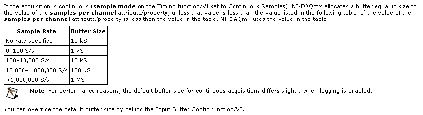
Regarding the ConfigureSampleClock, I have some doubts. I want a continuous acquisition, then I put the internal rate, signal source 1000, continuous sample mode, I set the size buffer using the parameter "sampled by channel.
What I wonder is:
(1) can I put any kind of buffer size? That the limited hardware of the module (9235) or DAQ (9188)?
(2) can I read the buffer, let's say, once per second and read all samples stored in it?
(3) do I have to implement my own buffer for playback of data acquisition, or it is not necessary?
(4) because I don't want to lose packets: y at - it a timestamp index or a package, I can use to check for this?
Thank you very much for the help
Hi Roberto-
I will address each of your questions:
(1) can I put any kind of buffer size? That the limited hardware of the module (9235) or DAQ (9188)?
The samplesPerChannel parameter has different features according to the synchronization mode, you choose. If you choose finished samples the parameter samplesPerChannel determines how many sample clocks to generate and also determines the exact size to use. But if you use streaming samples, the samplesPerChannel and speed settings are used together to determine the size of the buffer, according to this excerpt from the reference help C DAQmx:
Note that this buffer is a buffer software host-side. There can be no impact on the material available on the cDAQ-9188 or NI 9235 buffers. These devices each have relatively small equipment pads and their firmware and the Driver NOR-DAQmx driver software transfer data device to automatically host and the most effective way possible. The buffer on the host side then holds the data until you call DAQmx Read or otherwise the input stream of service.
(2) can I read the buffer, let's say, once per second and read all samples stored in it?
Yes. You would achieve this by choosing a DAQmx Read size equal to the inverse of the sampling frequency (during 1 second data) or a multiple of that of the other playback times.
(3) do I have to implement my own buffer for playback of data acquisition, or it is not necessary?
No, you should not need to implement your own stamp. The DAQmx buffer on the host side will contain the data until you call the DAQmx Read function. If you want to read from this buffer less frequently you should consider increasing its size to avoid the overflow of this buffer. Which brings me to your next question...
(4) because I don't want to lose packets: y at - it a timestamp index or a package, I can use to check for this?
DAQmx will meet you if all packets are lost. The default behavior is to stop the flow of data and present an error if the buffer of the side host DAQmx overflows (if, for example, your application does not pick up samples of this buffer at a rate equal or faster than they are acquired, on average).
If, for any reason, you want to let DAQmx to ignore the conditions of saturation (perhaps, for example, if you want to sample continuously at a high rate but want only interested in retrieving the most recent subset of samples), you can use the DAQmxSetReadOverWrite property and set it to DAQmx_Val_OverwriteUnreadSamps.
I hope this helps.
-
USB-6225 DAQmx measurement problems when using a voltagesplitter
Hi guys

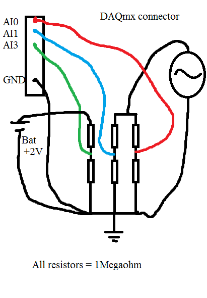
I had a serious problem regarding the use of DAQmx USB-6225. Please look at my diagram below:
When I measure the waveform sine on AI0, everything is OK. Even with a very sampling rate high as 80kS.
When I measure the waveform sine on AI1, everything is OK. Even with a very sampling rate high as 80kS.
When I measure the battery voltage on AI2 CC, everything is OK. Even with a very sampling rate high as 80kS.
Now comes the problem:
If I measure all three analog inputs or the two and two together, I get a very different result when I measured one and a single channel. If I add more channels (i.e AI3 and AI4) on my USB-6225 DAQmx, without connect anything to them, I can see the sinuses even as I do with AI0 AI1, but with less amplitude.
When I measure the voltage as well as AI0 and/or AI1, the domain controller becomes sinus armor as well. If I connect the + 2 V DC directly to data acquisition without resistance, I see a line perfectly DC on my chart, but with the sinus AI3 and AI4 top.
If I use an oscilloscope and measured directly on the same wire that goes to my data acquisition and the resistorcoupling, I can see small pulses of the samplingfrequency and the signal seems quite noisy.
That's my big problem:
Everything works perfectly if I use R<100Kohm. any="" value="" below="" 100k="" is="" ok.="" this="" coupling="" on="" the="" schematic="" is="" just="" a="" test.="" the="" trouble="" comes="" when="" i="" need="" to="" measure="" a="" circuitboard="" that="" draws="" energy="" from="" a="" capacitors="" in="" the="" circuit.="" if="" i="" use="" any="" resistors="" below="" 1megaohm,="" it="" draws="" energy="" from="" the="" circuitboard="" and="" the="" test="" is="" not="">
Anyone with some experience around this problem? The impedance of the analog input on my USB-6225 DAQmx is 10Gigaohm so it should not really been an issue.
Here is what I tried:
With the help of a D - sub cable with shield. I tried to use with no shield shield closed, I have both ends and closed, the shield only on my DAQ.
I checked my code and also just used the DAQ assistant.
I checked all parts off my setup for groundcircuits and I twisted each cable from any power supply, the signalgenerators, the DAQ cables.
I have connected my DAQ to mainsground (in the wallcontact 230V and Yes, we use 230V in Norway). Also any other equipment.
I connected without mainsground. Also any other equipment.
I tried cables as short as possible.
I tried to use the differential, CSR (Respect to GND), NRSE (Respect to the sense of IT). Nothing has worked.
I tried to use as sample rate and samples possible. (It helped a little when the DC measurement and AN analog input. If I tried all three, he has yet again).
All this comes to mind that the USB-6225 DAQmx cannot manage measuring more than resistors with values around 1Megaohm and above.
The answers will be rewarded with congratulations and a sincierly 'Thank You '.
Hi guys again!
Bother replying this thread

I'm a guy. I don't read manuals! But now that I did... And. There are 4 pages describing my problem and what to do about it. So problem solved
I have experience ghostvoltage of the other channels due to the high - impedance of the source. I created a follower of tension with an op-amp and the problem disappeared! Thank you ni.com/info/f/. Do you have answers for everthing is there to inquire. Except why I ran out of beer. mmm beer!
-
several modules in enet cDAQ reading problem
I have an enet cDAQ 9188 with 8 modules, including two 9213 modules CT and two 9215 ana in modules, reading a tc and an ana in each of the two screws. try different combinations of the order processed in the vis, all three modules will read ok, but not the fourth. Anyone has any ideas or experience read several modules at the same time with different screws in a cDAQ enet?
I now have a solution. Instead of a task read each module separately, read all the modules entry with the same task. Prevent resource reserved error.
-
Adjust the weight of race when the measurement problem
Hello
I have problems with the stroke on an object changing when I scale of this object. I already read to uncheck the "Adjust STROKE weight when climbing" but my problem is that option is greyed out in my control panel to "transform". When I go in edition > menus, there is a picture of "eye" next to him so he should be. I'm trying to figure out how to appear so that I able and then uncheck the box, resize a picture and keep the same weight of race at all times.
Thank you
Pat
You need to change your preferences. In the general pane, toggle the choice "when you descale" "apply to the content.
-
9233 can measure through a registry alternative voltages in a circuit, or any voltage-type sensor?
I have actually tried this, but uncessussful.
I guess it was because of the common source for IEPE in the module that gives 22.2 V when no load is connected.
I know, I can't swistch off the coast of the IEPE so that large 22.2 V voltage must strongly couple with my objective of the measure and thereby producing a date of trash.
Here's my question:
You know no-all about measure over again with the help of 9233, for example, one active adapter that converts DI to itself, or
to produce a DI (the problem is still the current source?), simply by using two channels SE?
Thank you in advance for the Korea
I don't know how to make it more clear. You posted your question to the wrong Board. You will have more luck if repost you your original question correct. If you did it correctly in the first place, you might have already been answered. If you don't want to do that, then fine.
To repeat
The measuring Chamber (where you posted) is for an old program of component snap to Excel. The add-in is called "measure". Measurement of the Committee name doesn't mean a generic measurement problems.
-
ItemRender creates 2 of each object. Problems of variable height TextArea
Ok. I'll start with what I was trying to explain how I found myself here. I tried TextArea with no scroll bar that resized at the height of the text. Googling, it seems to be the solution to do this is to expand the text box and use something like
var numLines:int = this.mx_internal::getTextField().numLines;
for (var i:int = 0; i < numLines; i++)
     totalHeight += this.mx_internal::getTextField().getLineMetrics(i).height;
this.height = totalHeight;
to calculate height. It works, but then I put the component (WrappedText) in a DataGrid control and used an itemRenderer on it and things went wrong.
What I see is that there are TWO WrappedText objects with just a line in the DataGrid control is created. The only difference when I go back is their parent, for example if I this.toString () in the creationComplete
MADE:  Main4_0.theContainer.theGrid.ListBaseContentHolder8.Renderer13._Renderer_WrappedText1
MADE:  Main4_0.theContainer.theGrid.ListBaseContentHolder8.Renderer27._Renderer_WrappedText1
The problem this causes is one of these objects a numlinesrequired equal the number of characters in the text. The other has the correct value (1). So what happens is the dataGrid Gets the wrong height.
I've trimmed everything down so there is only one line in the table etc. Here is the trace output. FACT is creationComplete of the WrappedText and RESIZE is when it recalculates its size (when the text is printed) and HEIGHT of the GRID is displayed by the creationComplete of the DataGrid
MADE:  Main4_0.theContainer.theGrid.ListBaseContentHolder8.Renderer13._Renderer_WrappedText1
RESIZE:  Main4_0.theContainer.theGrid.ListBaseContentHolder8.Renderer13._Renderer_WrappedText1 HEIGHT= 14 NUM LINES 1
RESIZE:  Main4_0.theContainer.theGrid.ListBaseContentHolder8.Renderer13._Renderer_WrappedText1 HEIGHT= 196 NUM LINES 14
MADE:  Main4_0.theContainer.theGrid.ListBaseContentHolder8.Renderer61._Renderer_WrappedText1
RESIZE:  Main4_0.theContainer.theGrid.ListBaseContentHolder8.Renderer61._Renderer_WrappedText1 HEIGHT= 14 NUM LINES 1
RESIZE:  Main4_0.theContainer.theGrid.ListBaseContentHolder8.Renderer61._Renderer_WrappedText1 HEIGHT= 196 NUM LINES 14
RESIZE:  Main4_0.theContainer.theGrid.ListBaseContentHolder8.Renderer61._Renderer_WrappedText1 HEIGHT= 14 NUM LINES 1
GRID HEIGHT= 1402
So my main question is this is a reasonable approach or y at - it another way not what I want? That is to say. a DataGrid that contains blocks of variable height, word wrapped text?
Also, can someone explain what is happening here so I understand what I am doing wrong, for example why 2 objects will be created?
Another interesting data point (?) is that if I put in an ObjectUtil.toString (this.parent) in the creationComplete of WrappedText the two objects get the value correct numlinesrequired example
MADE:  Main4_0.theContainer.theGrid.ListBaseContentHolder8.Renderer13._Renderer_WrappedText1
RESIZE:  Main4_0.theContainer.theGrid.ListBaseContentHolder8.Renderer27._Renderer_WrappedText1 HEIGHT= 14 NUM LINES 1
RESIZE:  Main4_0.theContainer.theGrid.ListBaseContentHolder8.Renderer27._Renderer_WrappedText1 HEIGHT= 196 NUM LINES 14
RESIZE:  Main4_0.theContainer.theGrid.ListBaseContentHolder8.Renderer27._Renderer_WrappedText1 HEIGHT= 14 NUM LINES 1
MADE:  Main4_0.theContainer.theGrid.ListBaseContentHolder8.Renderer27._Renderer_WrappedText1
GRID HEIGHT= 142
RESIZE:  Main4_0.theContainer.theGrid.ListBaseContentHolder8.Renderer13._Renderer_WrappedText1 HEIGHT= 14 NUM LINES 1
RESIZE:  Main4_0.theContainer.theGrid.ListBaseContentHolder8.Renderer13._Renderer_WrappedText1 HEIGHT= 14 NUM LINES 1
RESIZE:  Main4_0.theContainer.theGrid.ListBaseContentHolder8.Renderer27._Renderer_WrappedText1 HEIGHT= 14 NUM LINES 1
Note that the NUM LINES changed and the RESIZING is done after the creationComplete of the grid.
An explanation of the foregoing would be nice so why dumping simply the object causing completely different behaviors?
I have attached the source of my simple text program. Thank you
Stuart.
The creation of two converters maybe because the DataGrid creates additional converters purely for the measure. I think that this only happens if variableRowHeight is set to true. If you take a look at the source of the DataGrid and search for 'calculateRowHeight()' you will see that it calls the method "getMeasuringRenderer()" on each column to calculate the height of each row.
Your measurement problem can be because the width of the measurement converter is not set with the same value as the width of the rendering on the screen tool. I would put a breakpoint inside the method "setupRendererFromData" of DataGrid to see what the explicitWidth is defined. Looks like that the measurement converter should be set to the width of the column. Maybe set a width explicit on your column, if you do not already.
-
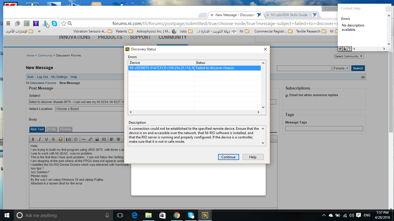
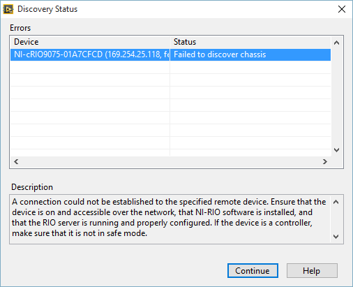
could not discover chassis 9075 - I can't see my NI 9234; NEITHER 9227; NEITHER 9263
Hello
I am trying to build my first program using cRIO 9075 with three modules in the series c NI 9234; NEITHER 9227 and NI 9263.
I use to work with NEITHER cDAQ, no problem.
This is the first time that I face such a problem, I can not follow the start-up of maula or any tutorial.
I stop at the part where all the FPGA does not apperar under my cRIO in Windows Explorer.
I installed NOR-RIO, which was delivered with the hardware device drivers.
Any tips?
Any Solution?
Please answer.
Either way, I use Windows 10 and alptop Fujitsu
Attached is a screenshot of the error
-
Hello
Is it possible to look at this as the registered user. Although the screenshots are good, it would be useful to see what the user.
Thank you
Ben
Hello Ben,
Welcome to the Microsoft Community Forums.
You can use the recorder measures problem (RP). The steps in the Windows 7 operating system recorder is a feature that allows users to record their interactions with an application and provide a detailed screen-by-screen display information that accompanies it. Action Recorder automatically capture the steps you take on a computer, including a text description of where you clicked and a picture of the screen during each click (called a screenshot). Once you capture these steps, you can save them in a file that can be used by a support professional or someone else to help you with a computer problem.
Are you trying to capture the steps in the form of a video?
If Yes, then you need to use some third party applications.
Note: Microsoft takes any responsibility for third-party applications.
For more information on how to use ESP, see the link: http://windows.microsoft.com/en-US/windows7/How-do-I-use-Problem-Steps-Recorder
Hope the information is useful. Please answer if you need additional assistance.
Kind regards
Deepak.
-
A measure of speed high speed with encoder in quadrature and NI 9401 on cDaq
Greetings,
We use an encoder in quadrature with 360 pulses/turn on the tracks (track A and B) and no trace of Z to measure motor speed at startup. Data acquisition, we use a NI 9401 in 9178 cDaq chassis and a pc with LabVIEW. The problem is that the start-up period is relatively short (less than 1 second), during which we measure speed as precisely as possible. The speed range is from 0 to 10000 RPM.
What type of measurement method that you would recommend.
Here are a few methods that we have already tried:
-Measure with DAQmx CIFreq--> high frequency with 2 counters: speed measurement, but with a very big mistake (+ 166 RPM).
-CIFreq DAQmx--> wide range with 2 counters: good speed data but more slow measurement,
-CICntEdges DAQmx (counting separated the two lanes, speed conversion): very incoherent speed data.
Thanks in advance for your help.
Matej
I would definitely say a 4, the measure of a low freq called option with 1 meter. (Frankly, I've never been
fond of this name because it is useful for freqs much higher than what I expect most people think "low freq".) This
is the method that I almost * always * use for frequency of counter measures. It works really well to capture transitional
variations in speed.
10000 rpm and 360 cycles/rev, you are looking at a maximum frequency of 60 kHz. The frequency measurement mode 1 meter
There will be 80 MHz internal clock by encoder cycle edges, then you will get more than 1000 strokes per measure. The point
that means only 1 number of quantization errors, you can expect<>
Further, you can average overall, say, 10 samples to you give even better accuracy and you could still be a data capture
rate significantly higher than the probable bandwidth of your mechanical system. (The average would just clean the jitter and noise and would not
Hide answer true mechanical characteristics).
-Kevin P
-
Heating problems Strain Gage; Wait for the function measurement of delay
Hello
I am able (using four 350 ohm gauges) of the strain using a NI 9237 module with a cDAQ in connection Full deck Type 3. My test is to measure the strain over long periods of time (~ 10 days). The NI 9237 measure strain at a rate of 2000 Hz (this is the slowest rate). The wheatstone bridge is currently powerd with the NI 9237 of 2.5 V. When I get my data permanently, I see the strain increases with time (which it shouldn't do my test), and I suspect it's because of free heating strain gauges. So, to overcome this problem, I think using "Wait (ms)" and ask the program to obtain data once every 5 min. Five minutes should be more than enough to dissipate any overheating of the gauge.
My question is: if I use the function 'wait (ms)', is my sensor (extensometer) are constantly under tension during the time-out of 5 minutes? I think that the functions "queue" are used inside a loop to allow a VI to sleep during the prescribed period (correct me if I'm wrong). So, it means that the sensor is not powered during this time?
Thank you
SID
I wouldn't use "wait" function for your timing... software you can use the time elapsed or other timing functions
-
sync problems - every shot is out of Sync exactly a quarter measure worsens with each take
Rookie X Logic Pro here - I have this problem, but not all the time, but each successive take is exactly 1/4 measure delayed the previous and out of sync with the runway, I add my track to.
Uh, what exactly do you do? Just save on a lot of tracks or what?
What version of OS X and LPX?
What audio interface / midi do you use?
-
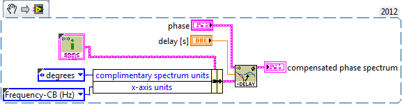
A swept the problem of sinusoidal displacement measure phase
Hi all
I'm performing a simple measure: I measure frequency response using sinus swept VI package audio and vibration. I just wire output signal to two terminals of input (chanels stimulus and response) - so I should get magnitude frequency response is equivalent to '1' at all frequencies and phase equal to '0' at all frequencies. However due to the fact that my card PCI (PCI-6251) is not able to save data simlutaneously, there is a phase shift that increases linearly with frequency. Is there a simple way to solve this problem?
Thank you!
Martin
You can customize the delay without DAQmx by setting the clock to convert frequency I. http://digital.NI.com/public.nsf/allkb/65E7445DB1AA5DC586256A410058697B?OpenDocument&nisrc=LV-2012
Devices for simultaneous sampling such as dynamic signal Acquisition devices should be used to simultaneous sampling of the guarantee (in hardware).
If you are satisfied that the current hardware configuration is optimal for your application, you can compensate the phase Swept Sine output using audio and vibration:
SVFA compensate time delay (XY) (1 Ch) .vi Phase
-
cDAQ and NI 9205 NI9203 NI9225 problem with the detection of modules
Hello
We bought a cDAQ-9188 and modules NI 9205 NI9203 NI9225. My problem is that the MAX does not detect these modules.
The cDAQ must be correctly installed and configured as it is in the list of devices. I checked the monitor of the device is running.
If anyone knows help me? Thank you
I've attached a screenshot of NI MAX.
The reason for this is that the firewall blocks him ports NOR resolved max. by adding exceptions in the firewall
-
With differential measurement noise problems
Hey everybody.
I use an NI USB-6211, LABView 2011 and Win7.
I'm trying to measure a voltage through a resistor using differential mode. But unfortunately im getting a lot of noise (on + - 25%).
The voltage source I use is variable and can go up to 600V. With my diet I am essentially heat a metal plate.
A parallel voltage divider is used to reduce the voltage by one hundredth (1 MOhm and 10 kOhm).
Two wires attached to the lower resistance then go directly into analog input 0 + 8 of data acquisition.
So if I'm trained 600V to the plate, data acquisition should get about 6V... and that's what I measure with my voltmeter attached to the acquisition of data input pins.
I also tried these resistances of POLARIZATION and connected the + and - leads to the analogous to the ground like a resistance I used 10 k, 100 k and 1 MOhm and 2 MOhm and
continue to receive a bad signal.
Two sketches of the wire as a signal (100V, supposed to measure 1V, no CORRECTION) are attached to the post.
Concerning
EDIT: I forgot to write that I even tried an another NI DAQ and still get this noise problem.
Also, I measured the voltage source signal using an oscilloscope and I see that noise. But the differential mode isn't supposed to
reduce noise to a minimum?
Hey everybody,
come to understand that the voltage divider resistors are medium to high and they were the main reason for the noise
problem.
Before I used 1 MOhm and 10 kOhm, now I use 100 ohm and 100 kOhm and with a median filter in this regard, it works very well!
But still, if I use the resistance of these BIASES they do not change.
Concerning
Maybe you are looking for
-
Improvement of ios 9.3.2 now requires using the unlock code
I have to use my code to unlock my iPad after the closing and reopening of the coverage. I did have to do it before the upgrade. I change all of the settings. My wife's IPad does not only. We each have 3 generation models.
-
Attachment MP3 will not play on the line of cellular data
I use RingCentral to my office PBX, which sends me voice messages by email as an mp3 attachment. Since the last update to iOS, I can't listen to these attachments on my iPhone 6s unless I am connected to WiFi. I checked all my settings and can not fi
-
I have a printer 8620. Y at - it a way or something I can add in order to print on printable CD.
-
scanning to PDF in Canon MX310 problems
Win7 ultimate - multifunction scan Canon MX310 with navigator MX software EX. After a couple of analytical documents and save to the PDF format, following similar scans are not possible. Display navigator MX bed 'impossible to save for not enough spa
-
Attempt to download Lightroom 6
I entered the serial number that was on the card that I bought, but he said that it was not a valid number. I tried 3 times and always got the same answer.