change digital controls of type int64
Hello
in my UIR, I changed the data type of a numeric control to int to an int64. Unfortunately, I'm not able to increase the maximum... 2 ^ 63 should give a number in the order of 9 x 10 ^ 18.
However, if I enter the CNC 1E18 ' Maximum:' my value is changed back to 2147483697. This is much like a 31 bit value, not 63 bit...
What else I need to do to enable the 64-bit numbers is displayed?
Thank you!
(PS: CVI2010)
This will be corrected in 2010 SP1. The reason the scientific notation works for non-int64 data type is because CVI stores these numbers as doubles. For example, if the control data type is integer, and the user types "2e2", we use strtod who convert to 200.0. However, we do not use strtod int64, data types because the double data type has only 53 bits in the mantissa, so any number which is entered which is greater than 2 ^ 53 may lose precision.
In order to make the numbers entered in the work of scientific notation for types of data int64 in SP1, it will use strtod if there is an 'e' or 'E' in the string. This allows the user to use scientific notation, but the number may be different from what has been entered if the number is greater than 2 ^ 53. This behavior will be documented.
Tags: NI Software
Similar Questions
-
How to change digital controls programmatically and radix indicator?
Hi all
I need to know how can we change the radix of CNC digital indicator while the program is running.
Kind regards
Pramod M G
Right. Sorry
 Format-> display Format
 -
As in the title. I want to create a digital control (no current limitation on its type) with a range of 1 to 10 (and a step of 1). The only difficulty that I have, is that the user should only be able to increase or decrease 1 at any time. Code initiated by this change of value must have completed at least once before that the value can be changed again. This is because code of VI is mainly contained in a while loop and control are read once at each iteration and its last value should not differ more than 1.
Is this possible with LabVIEW 6.1 and if so, how?
One of the solutions that I came up with so far is to disable the control immediately after its reading, and to turn it on again immediately seized is read the next time (I have to assume that the user is unable to click twice before the control is disabled). It is an acceptable method, or is there a better way?
I also had an idea of partially disable a normal digital control, such that it could not be typed in - only arrows remained operational. However, I'm not sure how.

James
Hi James,
You can use the two buttons (by releasing latch) and a digital display that shows the current value. Button increased the value and the other decreases. Store the value in a shiftregister to work with her.
I don't know if your solution would work because use may directly enter the new value.
It will be useful.
Mike
-
Dear friends
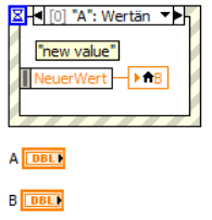
I have two digital controls in the front. Now I want to program numerical controls such as when I changed one of them another imposition of a change.
for example in the VI attached when I put 'A' 1 'B' must be automatically 1 to and when I changed 'B' 1 to 5 'A' should be replaced by 5 automatically.
Cordially Valentin
Hi VS,.
That's what it seems that for a value change event "A":
BTW. is it so hard to spell my name correctly?
-
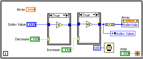
Can I use a digital control to change the illustrated index of an array?
Hey people,
This could be one of these questions, get feedback 'why would you do?', but I wonder if there is a fairly simple solution, I don't know everything...
I know that tables are not exactly gems when it comes to claims for benefits, but with my particular application, if I could get a digital control to define what the array index appears, it would be great. In addition, assuming that it is possible, then I think I could find a way to have two Boolean values which would increment/decrement the element indicated by updating the digital too...
Any ideas?
A popular entry!
THX
Is that what you wanted to achieve
-
A digital control takes no account of the limits of data at entry entry is typed, why?
Limits of data located in the property entry seem to have no effect on data entry. A value written to a property node limit the contribution of the increment of buttons but not the data which are entered in the control. How to stop digital control to accept out of desired range values? In the attached example, why I can type in any number for control and data entry limit is ignored?
In the Properties window of data entry for the digital control, you have the "answer of value out of range" ignore the value. Change it to compel.
-
Capture digital control last values
Hello
My front panel has several digital commands that I expect the user to enter data in before pressing a button that takes the values of the digital controls and
a power supply programs. What I discovered is that if a user types the digital control and does not support on enter or moves the cursor with the mouse to a new
control, the valleys of news are not captured when the button is pressed.
How to capture the most recent value in numerical order without waiting for the user to press ENTER after that that they typed in the value?
Two possible approaches to capture the value most recent inside a structure of the event:
(1) read the values of your digital controls in the case of events for the button. It is the simplest solution. If you need access to these numerical values in other cases of event, use the event to change value for these controls to update of the shift registers, or use a local variable.
(2) take advantage of the cause of the time-out period (if you are already using it you may need to do some creative re-use). Store the time-out value in register shift and set to default-1 so that he will not run. In your case of button, set the timeout to 0 shift register. Move your key event code in the case of timeout. LabVIEW will be re-read the values of your digital controls and the time-out event runs immediately.
-
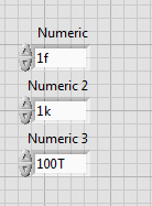
Digital control over several orders of magnitude
Hi all,
I'm trying to get a digital control with a suitable addition to the order of magnitude.
For example, I have a front panel for an osziloscope, sometimes that samples on some ns, sometimes a few seconds, sometimes a few milivolts, sometimes a few volts, who knows, right

I was playing around with the digital control units, but it doesn't quite fit my needs. I can't change the prefix of a unit on the duration, for example of microseconds to seconds, but then I change the issue as well, because on change the prefix, the previous number is only multiplied by the factor according to, for example, 1000, so 5 became US 5th-6s. So change the record length of the default value of 500 ms to 100 ns would require two klicks type, and I can instead just type "100th-9', which is good too."However, I would like to have a digital control from 0 to 1000 combined with for example a button for prefix i.e. nano, micro, mili etc. and combine this values internally, i.e. of mulitplying accordingly. But I couldn't set the increment to "3 orders of magnitude" even with the option to log scale.
I know, I could use an enum with the names and values according to, but this is not very satisfactory.
So perhaps the question would be: is it possible to combine two digital controls or the value for the prefix, in a suitable and easy way? Or how do you manage the digital values over several orders of magnitude in a case like mine?
Thanks for your replies in advance.
Best,
bastlwastl
Display format is SI units
It helps in these situations
-
Some otherwise identical digital controls have white behind the numbers, other gray
On the attached screenshot, there are two Express Digital controls in the lower right corner. I did the replace operation to make sure that both are the same type of control, still it white behind the numbers and the other is grey behind the numbers.
I do not change the settings of these controls when I inserted the. I don't see anyway to change the background number without having to build a custom control.
The two controls appear in the same loop, are of type DBL, floating point with 2-digit precision.
Can someone tell me why these environments is different and if there is anything I can do about it?
You must choose the background color to change the background of the indicator. Note that there are two color boxes in the choice of colors. The upper left corner is for the text. Bottom right is for the background.
-
strange appearance of the digital control
Hello...
I met a strange appearance of a digital control, see the below two screen captures.
Reminder: on a tabpanel, two of several digital controls have been changed programmatically if I put an indicator with a checkbox that is located on another tab of the Panel:
-control mode is switched / battery hot
-precision went from 6 to 4 figures to compensate for the space of digital arrows
These changes are applied to three checks, but only the first (highest) behaves unexpectedly, while others are very well...
(A) if both attributes are changed, the two top controls look like this:
in other words, the left most of the characters of the control are somehow overlapping, giving the impression of a fat o material
(B) if only the command mode of the higher control is changed to hot, the following result is obtained:
This makes it more obvious that somehow the two zeros on the left of the control are pressed together.
Interesting, if I operate the higher control by clicking on the arrow/top down, the result displays (1.0000E - 3) is ok.
I was much afraid to post this mystery which could well be a stupid mine mistake, but unable to locate a problem in the code, I thought that it could possibly be linked to the issue tab panel reported here
Comments, suggestions?
Thanks, Wolfgang
Hi Wolfgang,.
I checked your project, and it looks like a bug. I created a CAR. The number is 282946.
I guess that at the moment, you have to live with it or place the box on the same tab.
See you soon,.
RMathews
-
Update of digital control with different values with array function
Hello
I have attached my code base. I want to execute the code for 2 sets of digital control with a gap between the two values, then pass it. Something like that
ABC
Initialize the P1 = 10; P2 = 20; P3 = 30; P4 = 40
Run the code
delay = 10ms
Update of P1 = 150; P2 = 200; P3 = 350; P4 = 500
Run the code
jump to abc
I am stuck how can I update the values of P1, P2, P3, P4? I thought about using a function table but couldn't go further.
Thanks for the help,
Ana
Hello Ana,
One way you might achieve what you are looking for is using property nodes. These property nodes will allow you to change the values of the block diagram control. You can set up a structure of case inside your loop that will change control through nodes of property value after a certain number of iterations. Here is a community sample that shows how to use the nodes property to change the Boolean controls:
https://decibel.NI.com/content/docs/doc-22669
-Erik S
-
How to separate the 'down' key panel and digital control
Hi all
I have a key to proecess vi events for Panel and a digital control in this Panel. the app will do:
1. when the Panel is focused, allows the user 'up' and 'down' to the driver of some hardware.
2. when the digital control is activated, 'up' and 'down' change its value as usual.
somehow the other did not, because the round table 'touch down' was trigger as well when I use «to the top "'down' key aminata CNC.»
Then, I used "Key down?" digital control to block the "up/down" key But the first time, when I run the Vi, the Panel always got triggered only once.
any suggestions on this? test code attached to this post too.
Thank you
It works for me in 2014. In short, you just need to check to see if your digital has the focus. If it isn't, then you treat the value of the key. No need of any other event here except the stop button.

-
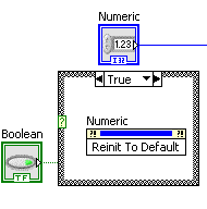
Digital controls by default Reint?
I am VERY new to LabVIEW and were loaded to think beyond my skill level. I'm sure it's an easy fix, but I am at a loss.
I have a digital control that changes of the user. The value of the digital control is then added with a reading of a strain gauge. I need to find a way to return the digital order to its default value. I read something on the forums on the use of a node to invoke, but I don't have a clue how to set up.
Thank you so much, in advance.
Thank you so much, I spent hours trying to use the loops and conditions. I didn't know where to put it in my program. One of the loops has finished the program to the point where the display was 5 seconds behind the data behind.
You guys are life savers!
Here is a selection of the node implimented. I used a button to "lock when you press on.
-
LabVIEW FPGA. Where should I put the custom controls - or type defs in a project
Hello
Maybe this is a stupid question - but I'm a little confused on where within a project I should put the controls (or type defs) used in FPGA screws. If you put in the bit "module FPGA" project, so they come up as "dependencies" - as if they are not in the project within the project when you read/write values in the target FPGA. Also, it seems that if you copy the project to a different location folder then the FPGA vi can be distributed in a way that she needs to be recompiled - even if you don't change anything - that's not cool if it takes an hour or two to compile.
I had the controls in the external project for awhile - but seems not ideal from the point of view modular programming, and also, it seems that it may also cause the recompilation unnessary - although perhaps less often that put them in the FPGA subproject.
Any thoughts?
I've seen the same behavior and it is a fact that the code must be recompiled if you move a project even if the FPGA code is unchanged. From my point of view, it's a real BUG. This is independent of any file source or target FPGA.
The other point of your question is not clear relly. Of course, you will get the dependencies if you place the necessary files outside the structure of the target project. But I see no problem to reference them twice because it won't double the source itself. So I suggest to refer to these files several times in the project structure. Actually I'm doing this because I manage a project file LV with different targets CRIO where the complete code for the target FPGA is double referenced under each target.
It may be useful
Christian
-
Digital control system, using limits of entry of data with global variables
Hello!
I have a Subvi with several digital control sliders. These control framerate, the pixel clock and exposure of a camera and their change in max/min/increment whenever one of them is changed - they are interdependent and get their information from the camera continuously during execution.
I'm trying to remote control this VI, but during the passage of a value using global variables, it doesn't "stick".
Example:
The value for exposure is 237,48 Ms. different values are constrained to the nearest value. So if I pick 240,00 ms at the Subvi, he should know that this is not a valid value and change to Mrs. 237,48.
But it is not do and I don't know why. When I enter the values manually, it works fine.
Any suggestions?
The limits on the controls that apply when their control from the front and is not passing values via the connector pane.
You should use something like "line and force" within the VI to validate the values are within the range (maybe constrain data or return an error).


Maybe you are looking for
-
I tried to replace the contents of the old profile folder to the new folder and I also tried to simply replace the urlclassifier3.sqlite file, but that does not work either. Googling didn't help me in the last 24 hours, but surely there must be a way
-
Driver WiFi unavailable for CQ43 403AU
Hi, I have a CQ 43 at THE its aswellas bluetooth wifi stopped working after I formatted the windows. I am using windows 7 ultimate 32 bit.In the Device Manager, to the title of the network card, only "realteck family pci controller" is listed. I have
-
BDDVDRW GBC-H20L CD/DVD does not work after update to Windows 10 Pro Windows 7 Pro this in Device Manager & this PC but when I double LK on this take a long time to load (it is called playing autoplay but does ' t), then it says Windows cannot access
-
Problems connecting to the internet with my wireless router
I have a WRT54GS v7 wireless router that I use with a modem ADSL ZyXEL P-660R-D1. during installation, I was unable to establish a connection to the internet, once my router is properly connected to my desktop computer and my modem. All the correct l
-
When using the tool clone in 2015 AE two things...(1) the video in the window of the model and the layer disappear or "blinking" and hold for a second, then disappears(2) the entire application freezesThis occurs after the cloning of 10 images or so