clock calendar - digital output
Hi all!
I need timing equipment impliment on a few digital output lines. That's what I have so far:
I didn't get an oscilloscope for her yet, but I'm fairly certain that it works. Please note that in this example, I use a PCI-6115. I have 2 questions:
(1) make what I do look reasonable at a quick glance?
(2) I'm kinda mistified by the entry of clock source to the example of the clock function. The analysis that I read just still confuses me. I understand that the clock is what dictates the sequence of material. I do not understand how to choose the appropriate clock source correctly. More specifically, in the above example, I've only had the program work when I chose "20MHzTimebase". What is c? Why this work?
When I try to select ' Dev1 / / SampleClock ", I get the following error:"attempted to perform a route when the source and destination are the same point."
When I try to select "Dev1/PFI0" or "RTSI0/DEV1", I get a timeout error in the wait_until_done.vi--> it does not appear that the waveforms are executed.
That means the PFI and RTSI acronym for, and why they appear as options when you select a source of the clock? Furthermore, why have they not worked as a clock source?
I would be very grateful to anyone who could clear things for me a little. Thank you!
Have you read the http://digital.ni.com/manuals.nsf/websearch/01C075FB9478F94A8625786A007435BA? manual The definition of PF and RTSI are here. They are designed using external clock signals. You have the choice of using the internal clocks of analog output (20 MHz) or external clocks. If you do not connect the RTSI bus or PF what, whether you have no clock so no data will be output. Selection of as source does not work because it is not a source. You provide a source for it.
Tags: NI Software
Similar Questions
-
Synchronization of analog and digital output with the external sample clock
Hello
First of all sorry for my English, I will try to explain what I want to do.
I want my PCIe-6321 to send two custom signals (modification sawtooths) on a mirror controller. I would also like to generate output with my card at the beginning of each tooth of saw. Everything must be synchronized with an external k-clock signal of 100 kHz. The idea is that whenever the PCI receives a trigger to external clock, it sends two analog output voltages and when he received 1024 clock ticks it will also send a pic of triggering TTL. What I do is first prepare the map and after that in a loop sending and modifing the output values of the two signals and at the same time send a digital signal Boolean in each arch, so when's done it 1024 iterations of the loop I send an event to the digital port. Attached you can see.
The problem is that I don't know how to synchronize both. Can I use the sample clock just to the analog output? I can use sample for the two outputs clock, or do I need to use the output of the meter? If don't know how to use it here.
If I do nothing else bad/wrong, I would be grateful for feedback.
Thanks in advance,
PabloI don't know how but I find the solution. I'm generating more than a positive value (as I was triggered maybe very fast the oscilloscope has been absent there). If I put the sample clock of digital output to use the sampling/ao/Dev1 clock that it doesn't, but if I put to use the same source as the OD (terminal where my external clock is connected), but the trigger to start the DO to be Dev1/ao/StartTrigger this works. I don't really know why, but it does.
Thank you for your patience and your help. I put here the final code.
-
How can I more easily generate a pulse of digital output of finite length?
Hello
I need to open and close the two pneumatic valves using a TTL output (without load current or the output power) using a PCI-6280 or PCI-6601. The valves must open almost simultaneously and closing after different amounts of time elapsed (millisecond level timing, maybe 100 microseconds-level timing at worst). My current plan is as follows:
-Create a task with two digital outputs (type of waveform) and another task with a counter that generates a frequency set by the user (I know I can use the generator frequencies on one of these cards, but I would have preferred a counter - the best selection of frequencies).
-Wire the output of the counter at the entrance to clock two digital outputs.
-Output of the meter is digitally triggered by another digital channel which I use to control if the pulse goes out. Through its counter node, it is programmed to be redeclenchables.
-Two digital waveforms are drafted who have both consist of unique active high pulse (i.e. signals go ' down (for the amount of time user-defined) - low ".")
-These signals is written to their respective ports and their tasks have started, as is the task of the meter.
-Whenever the user wants to open taps, digital triggering is sent up and then back to low (this can be done with synchronization software, because it is not exactly when the fire valves). Whenever the user wants the valves open for a different period, different digital waveforms are generated and written in the buffers of the digital output channels.
My problem is that it looks like a lot of effort for me to go and I wonder if there is a much simpler solution, that I don't know everything. You can program a computer to produce a pulse of finite length? Is there a faster way to program a digital output for that channel?
Thanks to anyone who responds to their help.
It is certainly instructive. Thank you.
The thing is, I have only six total counters to work with and I have a lot of time to do things. To use these solutions, I would need to use 4 or 6 account counters required to my needs.also that I would need to synchronize their departures.
Overall, I stick to my method for now - less system resources and synchronization can be don by using the same meter of finished output clock and not to use a trigger to all.
Once again, thank you for your help so far.
-
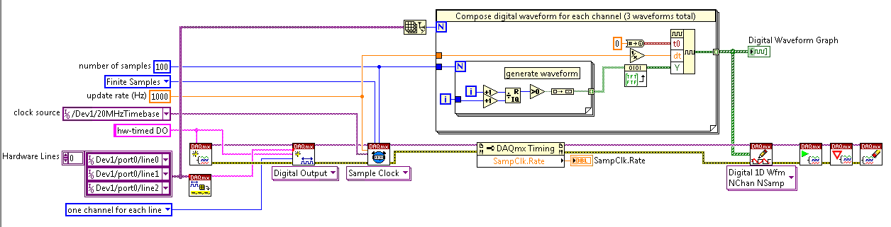
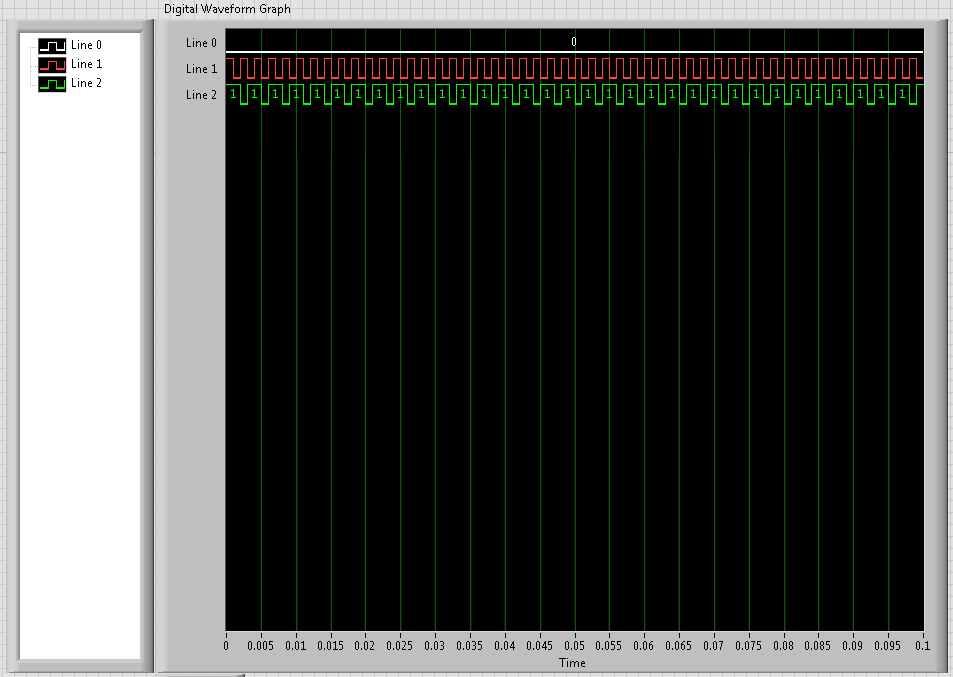
Well, I thought I had everything figured out, but we have finally had time to go to our lab and test it and there seems to be a problem with the output digital here. I'll look at what's the point of this VI, then describe the problem
Analog input is entered and analyzed as digital outpt is sent several lines (3). The digital output is used to send a single, user‑defined delayed pulse TTL with other instruments like triggers. I put this program to create an array of digital waveforms for each channel, each of them are of the same length as the analog input. '1' is inserted in the appropriate place in the table, in lieu of a value of '0', creating the required table. This table would be written on a digital line (1 channel, samples of N). Three of these subVIs are used here, so three signals various tables are created and writtin in its respective lines when the program runs, the analog input seems to work very well, but that a single digital output is executed. I need all three lines to write simultaneously.
I use a USB-6221 with LabView 8.2
I have attached all the files needed to run this program, and if the 'LabView programs' folder is saved on the C drive, I think that the paths of the files must be correct.
Thanks in advance
Hi Chris,
Hello and I hope that your well today.
Thanks for your updates.
I think that my being better if we start from the beginning.
1 could you try the example Correlated Dig writing with Counter.vi from the Finder of example of NOR?
It produces output meter as the time base for the digital output - to get clocked at digital output. Don't you see the waveform being printed on your outings that match the graph of digital waveform on the front panel?
If not, try to use one of the other examples, as Scripture Dig Port - this is a single VI just to send a single value for each digital line. If this does not work, there is a connection problem.
2. If we got this far without problems, then the next part would be to change the waveform so that you could write the data that you want to...
The digital waveforms can be made a boolean table, then using the array of Boolean DWDT to Digital.VI to convert into the type of digital waveforms. The waveform will have X number of samples. Therefore, at each clock pulse, you will produce 1 sample on each channel. So if you set the rate for 1000 and the number of points to 1000 (samples) it will display the waveform on a second. (as his continuous the DAQmx will make a loop through the buffer and start out of the waveform again).
Note, have you seen the palette of digital waveforms? It is located under waveforms and has more vi like the Boolean DWDT to digital.
Please let me know how you go.
-
Maximum speed of digital output of the DAQ 6009
Hi all
I'm trying to generate a clock the digital output on my USB DAQ 6009 puse. The maximum frequency, that I was able to produce was 0.5 kHz, but I would like to generate at least 1 kHz. I HT wired port0/$line0 of the OID of data acquisition to the data acquisition ai0 and attempted to read the output via the input of an analog of the same device. I have attached the programs here. Don't know if it's right. You can help. Thanks in advance.
150 s/s is the maximum rate of the analog output. The 48kS/s is the maximum rate of the analog input. Read a little more closely.
This unit will not do what you want. I recommend putting the hand of your representative local of NOR and discuss your needs with them. They should be able to set you up.
-
How can I improve my 2 digital output signals calendar?
Hello
I use a NI DAQ Pad-6015 (usb) with Labview 8.5 and XP to generate 2 digital outputs (high for the first 500ms and 600ms high for the second). The moment didn't need to be very specific, so I use not the 2 outputs hardware clocks. When runing of VI, and measure the length of the outputs with an oscilloscope, I get s 520ms and 640ms. This isn't a problem, but I still want to know, if I'm doing the right thing in my program, or if it is possible to improve it?
Thanks for your help,
Kind regards
Marc
Hello
Using all your advice I have exact measure now: only 0 to 4ms delay for signals from ms 500 and 600 using the NI DAQPad-6015.
PS: Timmer was right regarding the notice of usb. With my previous program when you use a card PCI of 6229, I had only a difference of 10 ms instead of 20 ms with the usb one.
Thanks for your help,
Kind regards
Marc
-
How to generate the digital output of the variable duty cycle and clock source being contrary?
I want to generate a digital pulse every front amount of my pulse counters. He must have a variable duty cycle. until now, I've been able to generate a digital output, but I can't change its duty cycle.
pls tell how I should proceed?
Thank you in advance...
-
analog sync of input with the onset of the digital output
I'm trying out an analog signal to a file with a specified frequency samples. I also need a digital output to trigger a measurement at a frequency specified on a separate system. The frequency is controlled by the loop exits and timed when the iteration number divided by the period is exactly a whole number.
Both outputs work. The problem is that they are not synchronized. The analog output amounts to about 0.5 ms faster than the digital signal. (I checked with an oscilloscope) They both start in the 1 ms each loop runs for, but I really need them to start at the same instant. What can I do to synchronize? Also, if I'm going in the wrong direction complete, please indicate.
I use a card PCI-6723, which I think someone at some point, said not having a material sample clock. That's why I try to use a timed software loop.
Hi NEA.
You must use the 6723's built-in calendar to accomplish what you want. As the digital output subsystem is only clocked by the software, an appropriate solution should be to use one of the counters to the pulse output.
The attached code should show how. You can use the counter to output a pulse all samples of the AO N task. Material requires the initial delay to have a minimum of 2 ticks, so the meter will be behind the task of the AO by 2 samples in this case. There are different ways to work around this problem if you need (for example write two samples of 0 first).
Best regards
-
redeclenchables strange behavior digital output
I created a redeclenchables digital dashboard task (finished) digital output as follows: (in DAQmx C)
DAQmxCreateTask("",&_taskHandle);
DAQmxCreateDOChan(_taskHandle,"/Dev2/port0/line6","",DAQmx_Val_ChanPerLine);
DAQmxCfgSampClkTiming (_taskHandle, "" / Dev2/Ctr0InternalOutput ", _clockRate, DAQmx_Val_Rising, DAQmx_Val_FiniteSamps, static_cast (_sampleCount)");
DAQmxCfgOutputBuffer (_taskHandle, static_cast (_sampleCount));
DAQmxCfgDigEdgeStartTrig (_taskHandle, "/ Dev2/PFI4", DAQmx_Val_Rising ");
DAQmxSetStartTrigRetriggerable (_taskHandle, true);
DAQmxWriteDigitalLines (_taskHandle, static_cast(_sampleCount), FALSE,-1, DAQmx_Val_GroupByChannel, _pDigital, NULL, NULL);
DAQmxStartTask (_taskHandle);sample clock:
DAQmxCreateTask ("", & _taskHandleCO);
DAQmxCreateCOPulseChanFreq (_taskHandleCO, "/ Dev2/ctr0","", DAQmx_Val_Hz, DAQmx_Val_Low, 0,0, _clockRate, 0.5 "");
DAQmxCfgImplicitTiming (_taskHandleCO, DAQmx_Val_ContSamps, _numSamples);
DAQmxStartTask (_taskHandleCO);When I run the task without redeclenchables parameter, it output a correct signal. However, if I run with redeclenchables it out almost exactly 2 times faster than normal. For example, a pulse whose width of 10 ms became 5 ms and repeats again to be 2 pulses of 5 ms. This is repeatable, no matter how much or how fast triggers provided.
My card is PCIe-6363. I do not know what causes this strange behavior, and I hope someone can help on this.
Thank you.
It disappears after reset configuration. Might be interesting for future reviews.
-
How to synchronize 2 digital output channels that have been created with DAQmxCreateCOPulseChanFreq
Hello
I use peripheral USB6221.
I created two digital output, operating on a frequency of 75KHz and duty cycle of 50%. But I need a period of 1 microsecond between the two channels.
I have craeted the two channel on the same task and guess if I use a delay of 0, the channels will be synchronized, but looking at the scope, the channels are not synchronized. Here's the code I used (I checked also all return codes of coarse and fine).
Thank you
Danny.
Int32 RetCode;
RetCode = DAQmxCreateTask ("", & m_OCtaskHandle);
LogMessage (RetCode, "CreateTask", "");
If (RetCode > = 0)
{
define the first output channel for 1 transmitter (75KHz)
RetCode = DAQmxCreateCOPulseChanFreq (m_OCtaskHandle, "/ Dev1/ctr0", ")
"Transmit1 Line 1", / * name to assign to the channel * /.
DAQmx_Val_Hz, DAQmx_Val_High,
0.0, / * initial delay in seconds * /.
75000.0, / * Freq * /.
0.5 / * market factor * /);
define the second output channel for 1 transmitter (75KHz with 1 microsecond delay)
RetCode = DAQmxCreateCOPulseChanFreq (m_OCtaskHandle, "/ Dev1/ctr1", ")
"Line2 Transmitt1", / * name to assign to the channel * /.
DAQmx_Val_Hz, DAQmx_Val_High,
0,000001, / * initial delay * /.
75000.0, / * Freq * /.
0.5 / * market factor * /);
Describe all channels continuous task
RetCode = DAQmxCfgImplicitTiming (m_OCtaskHandle, DAQmx_Val_ContSamps, 1000 / * I think that NA since continuous * /);RetCode = DAQmxStartTask (m_OCtaskHandle);
Hello Danny,
If you are looking for more output channels of the Digital pulse trains, you can create 1 task of counter that is used as the clock for digital multi-line data output. For this digital task, you will need to make the clock source line PFI for the output of your task of counter. Once this has been done, you will need to create the digital signal for each line of output and write to the card. The example called write dig Chan - Ext Clk will explain how to set up the digital task so that the task has an external clock (the counter). I hope this information helps you and if you have any other questions, feel free to post.
-
Manchester in transmission/reception of signals using the digital output of the PCI-6224
How a manchester signal can be sent and received using the OID of the pci card 6224?
I want to create a signal NRZ manchester on a digital output channel and then have the possibility to receive and interpret the same type of signal on a digital input channel.
Any help would be greatly appreciated.
Hi VJohnson,
You might find this post of discussion forum useful.
Looks like LabVIEW has not Manchester coding/decoding built, but do able in your VI by replacing all the elements with the corresponding elements of two and using double the speed of transmission as your clock frequency.
Thank you
Scott M.
-
audio output: optical digital output port (no sound!) macbook pro retina 15 mid 2015
My new recently Mbpr 15 inch has suddenly lost its sound, I went through the process of the toothpick etc but nothing. It worked perfectly fine earlier today, but I put in a mini jack into the headphone port and after to achieve 30 minutes later and taking the cable to THE that I had not his, then I had the red light coming out of the helmet but now its does not come in red and in the sound settings in system preferences its impasse on "optical digital output Port.
I now have to wait a week to wait until I can get seen at my apple store closet, I coming projects upward and in the middle of deadline and really using this Mbp to work, I literally only had a TI surly less than two months, I shouldn't have any problems. So if anyone knows anything I would appreciate it a lot! I need help to get this resolution as soon as possible! the last post I saw this was in 2006-2012 no new thread on this recently!
Thank you!
Jasonwaterz wrote:
I then had the red light coming out of the helmet but now its does not come in red and in the sound settings in system preferences its impasse on "optical digital output Port.
Try resetting the NVRAM/PRAM http://support.apple.com/kb/ht1379 memory
-
Realtek integrated sound card is stuck in digital output
I can't get this thing off the digital output mode. Now I have no sound because all analog ports do not work. Telling me that nothing is plugged. I can't reset the analog speaker because it is grayed in Vista. This problem seems to be very common with computers using Realtek and Vista, just do a google search and see for yourself.
I have a feeling it has software problem between Vista and Realtek. But I really think Realtek is just terrible to began with and should not be put in any period of the computer. If I can't get this thing works here tomorrow I will get a good real map.
Message edited by hn333 on 09/04/2009 21:02I had very similar problems and finally managed to solve it.
Something seems to be borked with drivers realtek about automatic jack detection.
After attempting to use the method described here (easier if you can) http://freeweelee.wordpress.com/2008/12/09/vista-and-realtek-front-panel-audio-not-working-solution/, I discovered that I was completely unable to cut jack detection in audio Manager Realtek (no folder icon).
For those of you who (like me) have no icon file, I managed to find another way to disable the detection of jack.
Using the registry editor, find all instances of ForceDisableJD and change the value from 00 to FF.
After making sure that I got all of them, I was able to reboot and everything works fine now.
-
No digital output on a Satellite P200
I just bought a Satellite P200 and am trying to put it to the test. Today I tried recording on a digital audio recorder (Edirol R-4) connected to the output digital output jack but can get no signal. I can get a signal from the analog headphone jack.
I have no problem with digital recording of my desktop PC which has an installed Sound Blaster card so it doesn't seem to be an incompatibility or a problem with the connecting cable.
I tried to set the default output to digital mode in the setup of REALtek but no difference.
Any suggestions gratefully received.
David
Anyone else had this problem?
David
-
Is it save to use the digital output as a digital input for another channel signal
Hi all
I know it's a stupid question, but I don't have another generator of signals by hand. What I want to know is, can I use the signal digital output of my USB-6001 as an input for the same signal device, but on other digital port? I wasn't directly because I don't want to burn the device...
Thank you
Done all the time. No problems.
Maybe you are looking for
-
9.3.3 broken store iBooks on iPad iOS
After the 9.3.3 iOS update (19/07/2016), the iBook store does not open on my iPad 9.7 Pro, or if it opens on my iPad Mini 4. My books works fine, just the star, Top Charts, etc. does not open. iBooks works fine on my iPhone 6s and iMac.
-
Need the latest driver of graphics for Satellite 5200 801
Cant just find the latest drivers, 3.6.3.8 does not work with this graphics card.Help, please.
-
Several analog inputs with different configuration differential/CSR
Hello Can anyone tell how to measure two analog inputs with different configurations using a USB-6009?I am aware of the syntax for create virtual channels for the channels DAQmx create virtual so I created two strings using Dev3 / ai0:1 but I would l
-
How to remove the error 0 X 800010108
-
How to remove files and folders called Rebateinformer
I found a file folder called Rebateinformer, I went to the control panel and found and deleted only he left 2 files one is rebategiant in my office and the help file for time denying me access to one know how I can remove remove them I tried to renam