Maximum speed of digital output of the DAQ 6009
Hi all
I'm trying to generate a clock the digital output on my USB DAQ 6009 puse. The maximum frequency, that I was able to produce was 0.5 kHz, but I would like to generate at least 1 kHz. I HT wired port0/$line0 of the OID of data acquisition to the data acquisition ai0 and attempted to read the output via the input of an analog of the same device. I have attached the programs here. Don't know if it's right. You can help. Thanks in advance.
150 s/s is the maximum rate of the analog output. The 48kS/s is the maximum rate of the analog input. Read a little more closely.
This unit will not do what you want. I recommend putting the hand of your representative local of NOR and discuss your needs with them. They should be able to set you up.
Tags: NI Hardware
Similar Questions
-
Configuration of the digital output in the USB-6009
I have a card for the acquisition of data USB 6009. It seems that him when DAQ card is turned on, it is always default to digital output of 'High' or 'floating '. I want to default to 'low '. Is there some setting I want to 'program' the hardware DAQ to have all the outputs low when it is powered on the value? Right now I have manually enter MAX and adjust the level 'low '. Thank you very much for your help.
Sid05,
Yes, it's low of 820 ohms. Unfortunately, the way in which the system is built, it is the only choice you have without having to build external circuits such as SnowMule suggested.
AK2DM,
Thanks for pointing the USB-6000. Finally a real, if limited, the DAQ hardware. Nevermind, he was only 4 DIO lines.
Lynn
-
create 4 pulse digital output at the base of the ttl input signal
Hello
I am a beginner in Labview and would welcome advice on how to solve the following problem.
I'm setting up a train of pulses TTL and would like to send in Labview as input. Each falling edge detected on the input signal, I would like to as Labview to generate 4 pulse digital output. For each output pulse, I would like to be able to specify the period and duration. The image should illustrate more clearly, with the figures showing the expected scale.

System: NI PCI-6733 data acquisition card, Labview 8.5
My daq card has 2 timers 24-bit and 8 e / s digital, but I don't know what the best approach is to create between the pulse output of 4 to 8 of this precision... should it be handled at the hardware or software level? And how would I go about it
Thank you
-Sidney
Hi noli.
I found the problem, in fact PCI-6733 support only avoiding the digital output. The timing of software is limited to 1 kHz in case better.
I'm sorry, but this function is not possible with a PCI-6733.
Concerning
-
How to configure the digital output of the pci terjeta 6023E in LabVIEW 8.5?
Hi, I have a card PCI-6023E and LabVIEW 8.5 and I need is to configure the digital output on the card, but did not.
My idea is to get a port of digital data on the map and control by a pwm small dc motor.
I wonder what are the modules with which you can do.Hi skudero,
Probably the web page tracking and the attached example will work.
PWM in software timing using a digital output line
Concerning
Charley - NIB - SR 1368189
-
Problem with a digital output in the information of an analog input
Hello
I use a SCXI-1000DC module with a module of the SCXI-1600, SCXI-1531 module and SCXI-1163 module to receive an analog of an accelerometer signal and a digital signal.
I claim that the accelerometer is constantly monitored, and the output is on when I want to, by an impulse that I comand in labview.
I use a rate 25 k and a 12, 5K samples per channel on DAQmx Timing.I notice in DAQmx read, if I put a sample of hight by channel, the output is not there when I want to, and if I put a few samples per channel, I exit when I want to, but the program seems to be slow with the passage of time. I don't know how I can solve this problem!
I'm sorry for my English, and I hope you can help me.
Thank you
Silvia
Hello Silvia,.
If you ask a larger number of samples, the labview diagram will stay longer in the DAQmx Read function, so the while loop runs slowly, and the digital output is updated less often.
I suggest that you use 2 separate while loops: one for the analog input and the other for digital output, so that each loop might run at a different speed.
Best regards
-
How to measure the digital output of the linear actuator on USB-6009?
Hello
I am a new user of Labview and need help to measure a digital input signal.
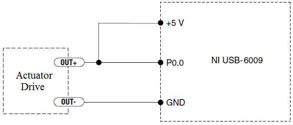
I have an actuator Bimba Original line electric with a motor continuous integrated with encoder, drive and the controller. The drive has a programmable digital output that I put as a tachometer output that emits pulses of square wave 100 per turn of the engine. I put the engine to make a total of 56 rev in 22 dry. I want to measure the speed of motor rotation labview real-time and synchronize it with a few other analog input signals. I wired the actuator for the USB-6009 case as shown below.
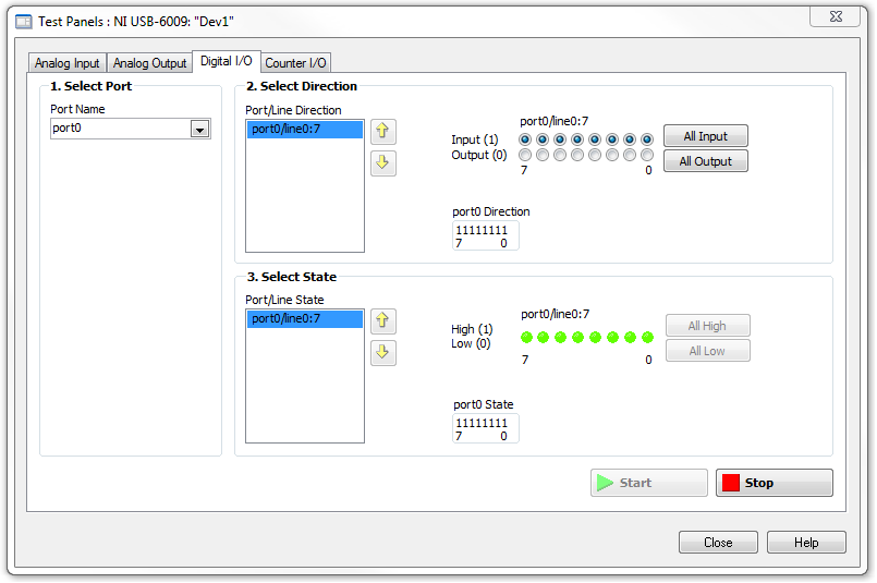
I opened the test i/o digital USB-6009 Panel and fix all the lines of port 0 as inputs. However, when I click on start and run the actuator, p0.0 led flashes, as indicated below.
Shouldn't the led blink in response to revolutions of engines?
I want basically to collect the drive pulse signals and convert them in rpm on labview.
ahsan2 wrote:
I have it wired correctly?
It would help if you do not attach the HIGH signal. Remove the + 5V in the circuit.
-
NEITHER 9205 digital output configuration with DAQ Assist
Hello
I have two NI 9205 Analog Input Modules which I have configured to read from each of their 32 channels. I used the DAQ Assistant help generate the vi which contains the task out - DAQmx event and also the DAQmx Read vi.
I used the Wizard twice, once for each module 9205 and then put the playback functions in a sequence structure so that only read would be carried out at the same time. It all works very well!
Now, I want to add in the code to wait in a loop before all loop containing playback functions, so that the user can press the GUI to send a logic 1 to the unit under test, and after it is sent immediately starts collecting data.
The DAQ Assistant Help does not recognize the module 9205 when I try to set up a task to write a digital output. 9205 a 1 digital output so why is the wizard does not recognize this? I also tried to create a task manually, but I got stuck.
Someone please help. I can reach the source if needed, but I thought that the descriptions above were sufficient.
Thank you
Gary
Hello
You are right it shows a line in this user manual, and in fact, you have found an instance where an important piece of information was left out of the documentation. This digital output line is actually only available when you use a cRIO chassis. It will not work with the chassis for the acquisition of data compact 9172. Here is a knowledge base that explains it. I'll also go ahead and file a request for corrective measures so that this note be included in the next version of this manual. Thanks for the comments.
Chris
-
Manchester in transmission/reception of signals using the digital output of the PCI-6224
How a manchester signal can be sent and received using the OID of the pci card 6224?
I want to create a signal NRZ manchester on a digital output channel and then have the possibility to receive and interpret the same type of signal on a digital input channel.
Any help would be greatly appreciated.
Hi VJohnson,
You might find this post of discussion forum useful.
Looks like LabVIEW has not Manchester coding/decoding built, but do able in your VI by replacing all the elements with the corresponding elements of two and using double the speed of transmission as your clock frequency.
Thank you
Scott M.
-
Synchronization of analog and digital output with the external sample clock
Hello
First of all sorry for my English, I will try to explain what I want to do.
I want my PCIe-6321 to send two custom signals (modification sawtooths) on a mirror controller. I would also like to generate output with my card at the beginning of each tooth of saw. Everything must be synchronized with an external k-clock signal of 100 kHz. The idea is that whenever the PCI receives a trigger to external clock, it sends two analog output voltages and when he received 1024 clock ticks it will also send a pic of triggering TTL. What I do is first prepare the map and after that in a loop sending and modifing the output values of the two signals and at the same time send a digital signal Boolean in each arch, so when's done it 1024 iterations of the loop I send an event to the digital port. Attached you can see.
The problem is that I don't know how to synchronize both. Can I use the sample clock just to the analog output? I can use sample for the two outputs clock, or do I need to use the output of the meter? If don't know how to use it here.
If I do nothing else bad/wrong, I would be grateful for feedback.
Thanks in advance,
PabloI don't know how but I find the solution. I'm generating more than a positive value (as I was triggered maybe very fast the oscilloscope has been absent there). If I put the sample clock of digital output to use the sampling/ao/Dev1 clock that it doesn't, but if I put to use the same source as the OD (terminal where my external clock is connected), but the trigger to start the DO to be Dev1/ao/StartTrigger this works. I don't really know why, but it does.
Thank you for your patience and your help. I put here the final code.
-
How to generate the digital output of the variable duty cycle and clock source being contrary?
I want to generate a digital pulse every front amount of my pulse counters. He must have a variable duty cycle. until now, I've been able to generate a digital output, but I can't change its duty cycle.
pls tell how I should proceed?
Thank you in advance...
-
Output analog, the USB-6009 case - can I use DAQmxWriteAnalogScalarF64?
I just got a NI USB-6009 and I try to use the outputs analog simple.
I'm running on a Mac, so I'll try to use the API OR-DAQmx Base 3.2 C (downloaded from here: http://joule.ni.com/nidu/cds/view/p/id/1078/lang/en). This is the most recent version of NOR-DAQmxBase, I could find.
I try to do continuous analog output on the 6009, which does not have a built-in clock. I was hoping to do the sync software and just new output values when I want to.
I can't get an output of database to work. Other messages and the example of Windows files, (e.g., National Instruments/NOR-DAQmx Base/examples/ao/MultVoltUpates-SWTimed.c) it seems that the best thing to do would be to use the DAQmxWriteAnalogScalarF64 function.
However, this is not in the Mac version of the C API of NIDAQmxBase. There is actually an entry for this in the NIDAQmxBase.h file, but it is commented out. Anyone know why? Is it possible to use this function for the analog output on request on Mac?
Thank you.
Clement
I have NEITHER-DAQmx Base installed 3.2 on a 10.4.11 system. One of the examples files 'genVoltage.c' calls DAQmxBaseWriteAnalogF64. I was able to compile and run this example with a USB-6009.
The DAQmxBaseWriteAnalogF64 function would work for you?
My guess is that, since you can write a scalar value with DAQmxBaseWriteAnalogF64, DAQmxBaseWriteAnalogScalarF64 becomes superfluous. The example provided with the installation shows how to write a unique value (i.e. scalar.). I pasted the code of OR below.
int main (int argc, char * argv [])
{
Task settings
Int32 error = 0;
TaskHandle taskHandle = 0;
char errBuff [2048] = {'\0'};
Channel settings
Char [] = "Dev1/ao0" chan
float64 min = 0.0;
float64 max = 5.0;
Sync settings
uInt64 samplesPerChan = 1;
Writing data parameters
float64 data = 3.25;
pointsWritten of Int32;
float64 timeout = 10.0;
DAQmxErrChk (DAQmxBaseCreateTask("",&taskHandle));
DAQmxErrChk (DAQmxBaseCreateAOVoltageChan(taskHandle,chan,"",min,max,DAQmx_Val_Volts,));
DAQmxErrChk (DAQmxBaseStartTask (taskHandle));
DAQmxErrChk (DAQmxBaseWriteAnalogF64(taskHandle,samplesPerChan,0,timeout,DAQmx_Val_GroupByChannel,&data,&pointsWritten,));
Error:
If (DAQmxFailed (error))
DAQmxBaseGetExtendedErrorInfo (errBuff, 2048);
If (taskHandle! = 0) {}
DAQmxBaseStopTask (taskHandle);
DAQmxBaseClearTask (taskHandle);
}
If (DAQmxFailed (error))
printf ("error in DAQmxBase: %s\n",errBuff); ")
return 0;
}
Hope this helps!
-
How to quit smoking all the void s vi before resetting digital outputs and then closing
I have a project that contains a main VI called home screen that calls many different sub vi. I am monitoring for a press of physical button by a digital input with a DAQ Assistant on the main VI and in this case I want my program to abandon all of its VI running and reset all the digital outputs before the closure of Labview. No idea how I would go all this?
I have attatched the basic model of what I do.
Joelspider33 wrote:
The problem is more to do with some of my money that VI running a DAQ Assistant using the same digital lines like the ones I'm wanting to reset and causing it to throw up an error message.
This is why you must set the DIO AFTER all subVIs are arrested. And to do this, you must send messages to these subVIs telling them to stop. If done correctly, it is a very quick process.
-
What is the current max on the digital output of a Terminal BNC - 2110
Im a using a card of data acquisition of 6221 with a block of connection BNC-2110 connected to it. For the e/s digital terminal block provides an additional 5V input. Unfortunately I don't seem to find any information as to know if this provides additional current to the TTL signal or no training. Is there an internal pilot in the terminal block, or - if I need to connect external relays to the digital output - always connect a current driver in between?
Thank you
Wolfgang
You can replay the 6221 and BN_2110 manual. The + 5V pins are outputs of the DAQ card - they are not entries.
Yes, you will need external circuits if the external relays require more current than can provide the DAQ card.
-
Is it possible to output a string and digital front without the border around it?
I know that I can change the border around a string or a digital output to the screen using modern or classic, but is possible to output and the numeric values to the front channels without the border around it? This is particularly useful for panels to front I want to print.
Thank you
Chuck
You are to halfway it using the conventional versions. The next step is to get out of your paint tool and paint the color of the transparent border.
Ben
-
Discordance between the DAQ rate Wizard and the dt output waveform
I use a NI 9239 to acquire analog input data. Using the DAQ Assistant, I put the N samples, 8 k samples read acquisition mode and the frequency of acquisition of 8 k. I wire the data output of the DAQ Assistant directly to an indicator of waveform.
I expect the dt for the waveform to be 0.000125. I have 0.000120, which is a rate of acquisition of 8333,333 Hz.
What I am doing wrong?
Thank you.
To read the 9239 specifications in order to answer your question. Focus on page 18/19.
Bonus tip:
You specify the MINIMUM for acquiring sampling frequency in the DAQ Assistant.
hope this helps,
Norbert
Maybe you are looking for
-
Why my computer loses its cursor and/or loses its and must use the mouse to go back?
I will be typing along and all of a sudden, nothing shows up on the screen and must use the mouse to get back. Also will be done solitare or another game and lose her and the mouse to move the things. Is this a virus? I updated my windows and nothing
-
Media types supported by HP DVD - RW AD - 7711H
I'm trying to find out what types of media are supported by the reader above - DVD + /, double layer, Blu - ray?
-
Connectivity Wifi U330p problem
Hello! It's about a week I have my new lenovo u330p and I have a lot of problems with the Wifi at my house. my laptop is 30cm distance from the router but 1,1.5 hourly, I lose my connection, so it works again if I go on airplane mode and then turn on
-
Hello everyone. I've heard say that windows 7 can help in running pc games without good gpu using the technology of the CHAIN. My question is that how can I use it? is it good?
-
EliteBook 8440p: Add USB3.0 to Elitebook 8440p
Hello. New to the Board of Directors. I am the owner of a computer laptop 8440p HPElitebook. I'm looking to upgrade to support USB3.0. I have nothing now. I'm not fluent that tech LT, but I don't see any replaceable units on my system. The + CD-