Coaxial connector in Multisim component
Hello
Im looking for a component of coaxial connector in the Multisim database as well as the site of components listed here. But I couldn't find one. Can someone get me a clue on how to find it. Thank you.
hers,
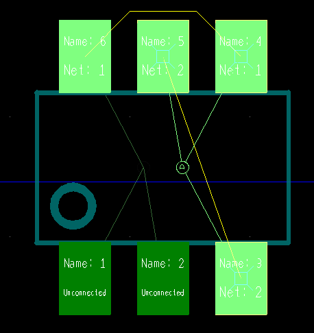
There are several symbols of 2-pin connector that you could use and attach them to the available Ultiboard fingerprints or footprints BNC customized based on what it takes, however, here is a diagram with a BNC connector for example with a standard configuration of symbol of the BNC.
Do not hesitate to register for databases, and customize with no specific information (that was created for a 50 ohm coax).
Kind regards
Patrick Noonan
Business Development Manager
National Instruments - Electronics Workbench Group
50 street market 1A
S. Portland, ME 04106
E-mail: [email protected]
Phone: (207) 892-9130
Telec. (207) 892-9508
Tags: NI Software
Similar Questions
-
compare the connector by programming component
Can we comapre the two screws prgramatically Connector components?
Hi John,.
If you use the vi attached, you get information on the model and what object is connected.
It will be useful.
Mike
-
lost functionality of the Multisim student trial
Hello
I'm 17 days on my trial of multisim student and from today I can no longer place components or instruments, but can open existing circuits and perform simulations. Any ideas?
Thanks, Dave
Hi Dave,.
The toolbars are grayed out? Take a next look in the knowledge base:
Grayed out in Multisim component toolbar
Kind regards
-
It seems to me you download Multisim component evaluator, Analog Devices, v. 11.0.2 successfully and have uncompressed the 337 files. By clicking on the icon of the program returns me to the user account control window, which leads to the process of the United-zip Nations. How to escape from this loop?
Hi Rgaze,
The file downloaded from the Web site is a self-extracting zip file, and when you double-click it, first of all, the installation files are extracted to your local hard drive: C:\National Instruments download. Once the files have been extracted, you should get a screen with the option to start the installation. If you have already gone through the installation already, click the Windows Start button > all programs > National Instruments > Multisim component evaluator > Analog Devices Edition > Evaluator component Multisim 11.0 to launch the software.
Our installation does not add a shortcut icon on your desktop so if you double-click on the file you downloaded again, you repeat the process of extraction and installation of files.
-
How the value vias of the connector a specific NET?
Hi all
I placed the SMK8R5MIL_B fitting on the top layer of the CCP, which is like 8 slider to pins. The connector is basically will be used in order to connect various energy sources. I can't find a way to assign individual vias of the connector to a specific network. Any help would be greatly appreciated.
Thank you.
Hello
The best way to add a connector is to do in Multisim and then before annotate by selecting transfer > annotate with impatience to Ultiboard. The PCB design, you are working on that will remain the same, but you will have the connector added in the schema available with all nets installation. By adding the connector in Multisim synchronize its average will remain your schematic and PCB, adding pieces in PCB design is only bad design practice and in many cases, you will have a lot of problems in the future if you need to make changes to your design.
If you have not created a schema that you want to assign pins to nets in Ultiboard, select Tools > Netlist Editor, under 'Net', click the menu drop down and select a net, click on the button with an arrow in the picture and then click directly on the axis you want to add to this net, it will be apear on the "Pin" tab. If the PIN is part of the other net, Ultiobard will not let you select again.
Yet once, do it in Multisim if you have a diagram.
-
Coaxial optical drive from Console
I just bought an Optiplex 3020 M (micro) and the optical reader Console. Viewing the back of the console, there is a very small coaxial connector. It is attached to a small "brick" mounted to the back of the Assembly, but on the inside. No one knows what it is or what it is?
See if the Manual answers questions on the Console microphone w/DVD player, beginning on page 13.
For the antenna cable... ?
-
Stuck in the mud of component Label
One of the numbers displayed on the right side (under drivers lost etc.) are generated in a component of the label of an XMLconnector component relationship.
The obvious problem, it is the color of the text and size.
I tried google and other responses from forum without success to change the appearance of the label component.
Any advice would be appreciated seriously.
XML connector and Label componentOK after hours of reading, electronic mail, sometimes referred to as stupid Bonehead thought of her research.
uniqueID_lbl.setStyle ("color", "white");
In the Inspector of components for the uniqueID_lbl instance make sure you html is false. -
Other drivers for 2014 X 1 carbon GOBI 5000?
I noticed a few other discussions about the card WWAN 5000 GOBI on 2014 X 1 carbon machines, so I know that I'm not the only one with questions... I have two new X1s (two 20A 7), one with a GOBI Verizon 5000 and another with a GOBI AT & T 5000. The Verizon card installs very well and is working, no problem there. AT & T has in turn map: not presented all the Device Manager, presented as an 'unknown' object and now after uninstalling the driver, in removing the card, restart, re-install the card, etc., the driver package installs successfully, but the map appears under ports such as COM4. The description is correct - system sees it as a «Sierra Wireless EM7355...» ». Of course, Mobile Broadband Activation does not see the card and therefore will not work.
In another thread, someone suggested they could get their hands on an older driver package that has been installed successfully. hope to get a link? Or, better yet, a update driver current?
welch_pm,
follow the page below:
http://support.Lenovo.com/en_US/detail.page?docid=HT081505This is the activation of Gobi 5000 at Verizon Wireless, but there is a chance the reason for your problem is the same - it is necessary to change some parameters of internal modem. Make sure that the values of DAFAULTIMAGE is 2, USBCOMP is 14
----------
hsleviant,son of WWAN antenna you saw inside the laptop already had need of coaxial connectors for the wwan card. Just fit the card and carefully connect the wires.
-
CQI IMAQdx continues FireWire DVCAM
Hello everyone,
I have a (old) Hamamatsu analog interline CCD camera C5985 where images are digitized by a sony DVCAM DSR11. The digital video output is connect on PCI Firewire on the PC and a TV card
With the acquisition of visoin Wizard, I continually get these images and get this kind of frame interlaced instead to get a homogeneous place
It seems to show that a part of the image, no?
How can I do to avoid this intertwining?
Thank you very much!
Hello AndGar,
Thanks a lot for your attention and your response,.
I install that update Vision CQI and all seem to be ok. I now have a seamless task as you can see:
There are no interlacement now!
There is also an analog video output (coaxial connector) on the camera C5985, whitch can coupled directly on a TV screen and the DSR11 with a Coaxial base / RCA adapter.
Thanks again,
Best regards
KALAKUTA
-
MOSFET, modeling of the measures
Hi all
I've taken a few steps (for the most part IV tanks and others) on one of my classmates built a transistor and I want to simulate it in Multisim. I panned on just edit the template for the virtual PFET. Could someone please tell me where I can find this as all of these variable stand for?
+ (
+ LEVEL = 1
+ VTO = 0.0
+ KP = 2.0E - 5
+ GAMMA = 0.5
+ PHI = 0.6
+ LAMBDA = 0.001
+ RS = 0.0
+ DR = 0.0
+ CBD = 0.0
+ CBS = 0.0
+ IS = 1.0E - 14
+ PB = 0.8
+ CASE = 0.4e - 9
+ CGDO = 0.4e - 9
+ CGBO = 0.38e - 9
+ RSH = 0.0
+ CJ = 570e-6
+ MJ = 0.5
+ CJSW = 120th-12
+ MJSW = 0.5
+ JS = 10.0E - 9
+ TOX = 9.5e - 9
+ NSS = 0.0
+ GPT = 1.0
+ LD = 80.0e - 9
+ OU = 460,0
+ KF = 0.0
+ AF = 1.0
+ FC = 0.5
+ TNOM = 27
+ )You can find here Multisim component reference:
http://www.NI.com/PDF/manuals/374485a.PDF
Page 149 is the discussion of the MOSFETs.
-Pat N
-
can I connect a bently nevada all sensor 3300XL 4-channel NI9234 DAQ
Hello
We bought a 3300XL Bently Nevada proximity sensor which comes with a Miniature of the ClickLoc coaxial connector with protective connector, standard cable. We have a 4 channels NI9234 DAQ.
Please any suggestions on the type of adapter to use?
Thank you.
I'm not an engineer OR app, but as far as I know there is not NOR-DAQ with a V-24 and a - reange of 20V input supply.
Maybe the other way around: what does measure? Your sensor seems to have a fairly high nonlinearity... maybe get another sensor?
-
Make the REQUIRED Terminal Subvi
I have a vague memory that there is several years (LV 8, maybe?) there was a LabVIEW option (Tools - Options) to make all new Subvi input terminals by default to REQUIRED.
Would IOW, brand-new VI who had a created input terminal, the REQUIRED value. You can always set it otherwise, but this is the default value.
I tried then, and it worked, but was not suitable for the project, I was on that.
In looking for it now, I can't find in LV2013 options.
() I'm missing it - it's right there in the _ section.
(), It is removed and is offered by the key _ in 'LabVIEW.ini.
(), It is deleted and is no longer available.
() I imagined all this.
"Select Tools» Options ' façade and place a check mark in the default connector required CheckBox component terminals.
From: https://zone.ni.com/reference/en-XX/help/371361K-01/lvhowto/specifying_required_recomm/ -
I need a 74HC259 8-bit addressable latch. In the Multisim component reference, I found an entry for "74xx259" but I can't really find this chip anywhere. Can someone help me get this chip in my Multisim? Thank you!
It seems that this component is not available in the student version. I placed the component on a design. You can copy and paste from here when you need to use.
I hope this helps.
-
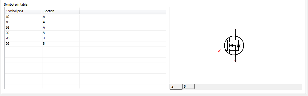
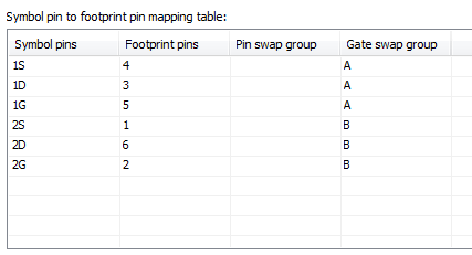
I have some difficulty with door swap on a custom in Multisim 12 component. I created a footprint Ultiboard and Multisim component for a packet of transistor double. I did a component of several section. I used the same PIN naming convention as used in Master part of database I can door swap successfully:
I put each section in a different door permutation group:
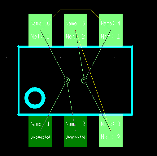
I place the component, make a few connections and transfer to Ultiboard. When I go to Design > doors of Swap, the pop as expected. However, when I click on door, door B goes and my only option is to click the door A once again.
When I do that, I get the message 'doors cannot be exchanged. Of cousre, I don't want to swap gate with A, because who would do anything, I want to Exchange A with B and I'm not sure that I could get hurt.
Please let me know what you think and thank you for your time.
Thanks for the file. I was able to reproduce the problem, and after having tested various scenarios I discovered it as a possible defect of the software. It seems that when the custom component uses a fingerprint in the database of the user, door information Swap is transferred correctly to the Ultiboard.
Our developers will take a thorough review of the issue; referring to the request for Corrective Action is for you: 488146.
At the moment the only suggestion would be to make the changes (door swap) manually in Multisim, and then annotate with impatience to Ultiboard. The other option would be to use a size of the database, of course, as long as you find the right footprint there.
We apologize for the inconvenience.
Kind regards
-
Dear ppl, I'm trying to simulate a high-speed diode as mur1650 ct.
It s a 500 volts, 8amp 60ns switching a used as dc motor free-wheeling.
Could not find something similar to the database, so I was wondering if it is possible to choose a different diode, with
similar settings and modify it, so that he behave like a mur1650.
What do you think?
Hello..
Below is a tutorial on how to create custom components of NI Multisim. This tutorial also includes a video that shows you how to navigate through the process of creating a custom component.
Creating a custom NI Multisim component:
http://www.NI.com/white-paper/3173/en/
http://www.NI.com/white-paper/11753/en/See you soon

Maybe you are looking for
-
iMessage does not work after update phone
I just updated my iPhone to iOS 9.3.5 5s last night. Since then I've known a lot of problems, but the most important is that my iMessage no longer works. I only receive some texts/iMessages and can send without any texts/iMessages. I have attempted t
-
Color Laser Jet MFP M177fw Pro: Duel side printing
Is it possible to put this machine do Duel back?
-
Unusable M110 of Dell and black color...
Hello So I bought recently two M110 of dell projectors. They are sharp, bright and look great. However, they are two TOTALLY INUTILISABLES because they are unable to project correctly when the majority of the screen is black. I took a video that il
-
Why go down my screen resolution
I was updating my driver display, and when you have completed the tool I was using it disconnected my second monitor change my screen resolution of 1440 x 900 to 800 x 600. Display does not show the 1440 x 900 more option and it shows that my monitor
-
Cannot open a downloaded video filei blackBerry smart phones
I downloaded several files but some are not open, can you please help me because I have tried everything I know to open them but failed