code generation c as mathematics-works real-time workshop
Hi John,.
have you tried to search the forum?
See here or here. Search for "embedded LabView!
Tags: NI Software
Similar Questions
-
OR PCI-5640R serving of real-time Spectrum Analyzer
Hello
The code for the demo of the real-time Spectrum Analyzer real NI SMU-5641R is shown HERE for LV 2009. I want to use the same code for NI PCI-5640R NI SMU-5641R instead. Since I'm on a 5640R, I changed the device in the project.
Can someone guide me what else I need to do in this demo code so that I can use the same code for the NI PCI-5640R
instead of the SMU-5641R NI?Thank you and best regards,
Rashid
Hello r,.
Since you have not mentioned I guess that you do not have NI 5600. Therefore, to make this example work, you will need NEITHER 5600 buck frequency converter and driver of DAMA. NEITHER 5640R serves only as a digitizer in this case. Also note that the 5600 is the resource name hardcoded in the program, so if you have OR 5600, you can either rename in 5600 Max or change the name of the resource in code for matching a max. You also need re 5600 NOR as a DAA, so so right click on 5600 OR in select Properties MAX and select external under scanner. All should be good as long as you recomplie the project to create a new file of ILO.
Thank you
NOR-khil
-
Real-time application does not work; source code works very well
The short version is I'm programming a cRIO and apparently the RT code isn't running after you deploy, and I can't understand why. It is further complicated as I do all this remote and I don't have direct access to the unit since I am 500 miles away. I work through a couple of other guys who know some LabVIEW, but neither is working on the site so that they explicitly trip there whenever I have a bright idea.
I was there a few weeks ago. During this time, I created a code simple cRIO, since I'm new to the cRIO, allowing the user to move a control and change a chart. It worked fine, but I must stress that it did not have a FPGA component. After that, I worked on the actual code, which reads some sensors, displays the results on a user interface and stores the results. Did FPGA. I used it in the LabVIEW environment and it worked fine, but I ran out of time before I could finish a release build and deploy the RT as a compiled application. I sent them the version later, my contact deployed but had the network stream errors during execution of the user interface.
After hours to address network problems and sending over debug versions, I tried to create a log on RT level so I could see what was going on. The journal is not yet open, even if it is the first command in the code. I have pores through the forums and found http://forums.ni.com/t5/LabVIEW/cRIO-Troubleshooting-creation-and-deployment-of-startup/td-p/1956475... which took a new direction.
I had my contact use the RT debug console and when it pulls up to the front of the RT, it shows an arrow broken at delivery. He clicked and nothing happens - no work, no list of bugs. If he shoots to the top of the list of bugs manually, it is empty. Again, the RT works very well if you run it through LabVIEW and not as an application compiled in real-time. He also noticed that the open FPGA VI was grey on the block diagram. Are no other icons.
If the problem seems to be that the compiled application of RT becomes some kind of error, but do not tell me what it is, and it seems to be related to the opening of the FPGA. I recompiled the FPGA and RT. I recompile the RT himself, but not the FPGA, because this would take hours. It is download everything properly for the cRIO. The RT is set to run automatically. It is restarted the cRIO whenever he deploys the RT. They have LabVIEW on a computer, but it doesn't have the correct drivers to run the code of the environment of LV. I am to resist have them install the dirvers because downloading big files is complicated due to the restrictions of security as well as a lousy connection at a remote site. In addition, it does not solve the problem of RT executable doesn't work is not the same as the source code, which, according to the thread above, seems to be a thing.
The last thing I'm getting is that I sent her instructions for how to build a source distribution of the project that I sent and try to deploy on the cRIO. Even if it works, I'm not sure that this is an acceptable solution, because I assume running VI, rather than the EXE is slower, and they need to speed on this project.
Simply, I don't know where to go from here. I probably need to get direct access to the cRIO and I might be able to convince them to ship to me so I can understand this point, but I don't know where I got same departure other than the Voodoo debugging standard of "trying stuff randomly until something works". I am open to suggestions, if someone managed to solve this before.
Code snippet of the first part of the project is fixed, although I don't know how much what good it will do. I am really confused, and the customer is frustrated with how much budget is going to solve this problem.
-
UDP playback does not work on a real-time target
Hello
I am running LabVIEW RT 8.6.1 on a PXI 8106 RT controller. LabWindows/CVI for RT 9.0.0 execution engine is also installed that I develop using LabWindows/CVI 9.0. I'm trying to send some data UDP for an external PC via the network for software running on the controller, but this does not work. The UDP packets are certainly get sent (I receive on my PC when the transmitter to reconfigure my PC IP address) but the UDP callback function is not called. The call to CreateUDPChannelConfig returns OK. Here's the (very simple) code that I wrote based on the example of reading NI UDP:
#include
#include
#include

// Global variables
static int reader_channel = 0;

// Global functions
int CVICALLBACK UDPCallback (unsigned channel, int eventType, int errCode, void *callbackData);

/// HIFN The main entry-point function for the Real-Time DLL.
void CVIFUNC_C RTmain (void)
{
    int errno;

    if (InitCVIRTE (0, 0, 0) == 0)
        return;    /* out of memory */

    // Create UDP receive task
    errno = CreateUDPChannelConfig(49152, UDP_ANY_ADDRESS, 0, UDPCallback, NULL, &reader_channel);

    while (!RTIsShuttingDown ())
    {
        SleepUS (1000);
    }

    CloseCVIRTE ();
}

int CVICALLBACK UDPCallback (unsigned channel, int eventType, int errCode, void *callbackData)
{
    static int udp_received = 0, default_rx = 0;

    switch (eventType)
    {
        case UDP_DATAREADY:
            udp_received++;
            break;
        default:
            default_rx++;
            break;
    }

    return 1;
}
All that happens is that software is just waiting for the callback to be called (which never does). I found this ad that described a similar problem, but the developer was using LabVIEW and although he has found a way round the problem, he was never heard as to why it worked.
Thank you
Martin
Hey,.
Although the problem is now resolved, I thought that put the code for others see if the same error is encountered. The modified code is tested and works. It is saved as an attached png file.
-
Structure of the timed real-time event loop does not work
I'm a new user for LabVIEW. And I've encountered a problem that frastre really me! Hope someone can help out me. Thanks in advance!
I just want to use the structure of the event under timed loop, which is important in my extrmely design.
However, this works very well in my computer (without connecting to the FPGA).
Once I connect it to the FPGA, then I can still run but there is no response!
My file is attached. Please someone help me!
Looking forward to your answers!
The FPGA runs headless. Structures of the event won't work. What you need to do is to have an application on your host computer when the user presses a button, changes a value, etc.. This event should send a message via TCP/IP for code that runs in real-time environment. Then the real time environment should attribute to the desired value a control on the FPGA.
As a general rule, programming real-time with FPGA has several layers.
(1) host-> handles interactions with the user code and communicates the code in real-time via TCP, UDP, etc.. Displays the user sent by RT controller data.
(2) code in real-time-> tracks headlessly. Manages host code messages, processes the data of FPGA, communicates with FPGA much as the host code communicates with the code in real-time
(3) FPGA-> no acquistion and passes through PEP in the RT
The first thing you need to do is to understand the architecture and how all these pieces of the puzzle work together before you throw things down on a diagram.
-
Re-use of dynamically called code of target in real-time on PC
I have a code that is deployed on a target in real time what I call dynamically. I also want to use the same code dynamically on a PC in the same project.
This works very well when you run interpreted code in form. However, I can't add the dynamic called VI to build on my PC specification if the VI is under the aim of RT in the project. I can only include it in the build specification that is in conjunction with the software to the target of the RT.
How can I use this VI dynamically in the ad for the construction specifications and places without having two copies of it?
I actually found a way using a static reference of vi:
Rather than providing a path to the file of the 'open' vi reference, simply load the VI statically and I then enter its name to open an instance, re-entering. This approach has the advantage of process Dynamics called VI as if it was dropped on the block diagram - I don't have to explicitly include the vi file in the build specification.
-
Real-time execution trace toolkit to optimize the Labwindows/CVI code
Hello
I am trying to optimize a code in real-time in LabWindows/CVI by minimizing the time of each section of the code is taking and find bottlenecks in the code. I check this time using the real-time execution trace toolkit.
However, I just found it seems to be a constant error when you use the tool of real-time execution trace.
When I put the traceviewer 'start' and 'stop' right after the other, I get around shift schedule 9us. It seems that the CPU will in some "idle" after the start of the trace mode, or maybe it's the time of communication or something.
I'd appreciate it if someone could give me an idea of why this is happening. The time of real-time application window is very limited and I'm trying to minimize the time as much as possible. Even the United States 9 error is difficult to resell.
I used the following code:
TraceConfigure (1, 1, 0, 25000, NULL);

TraceStart ();

TraceStopAndSend (HOST_ADDRESS);
and there is a photo in the toolkit of real-time execution trace.
Thank you.
Generally, you might be better off picking off the clock at the beginning and end of what you want to track. RTETT my introduce overhead that becomes difficult to quantify... Which is what you probably already see. The debug mode will also implement a ton of overhead. Then... Destemming of the clock in release mode will probably give you you the best estimate.
-
How can work in real-time my vi?
Hello
I have a vi that use a lot of loop in loop (as 128 * 128) in there.
and to use an equation (contains: n! & gamma (n)) on this subject.It works fine but the problem is: when I click on the thumb, it takes about 1 second to respond to be broadcast.
but I want to run in real time. and want to meet be ready less than 50 ms.What is the problem? and what do I do?
Thank you
-
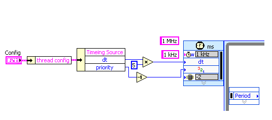
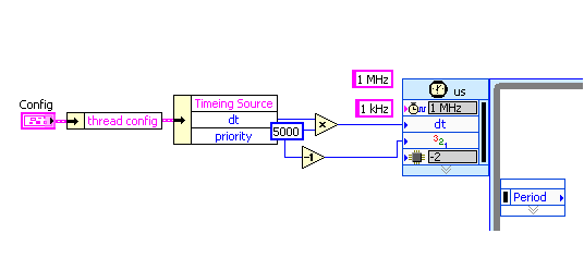
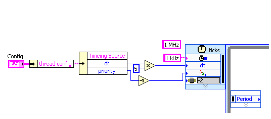
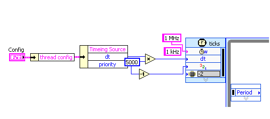
"1 MHz" for the name of the source on the time loop does not work on LabVIEW Real-time 9.0
A Loopis Timed running as expected if a time source is manually chosen in the dialog box of configuration for "1 kHz" (first digit) and "1 MHz" (second digit). If the time Source name is set through the input of the channel "1 kHz", the loop is executed, too third figure). But if the input string is "1 MHz", the loop is not executed (last figure). The channel two are created by "create constant" on the entry of the loop to exclude typos. Is it possible to set the Source of a loop time timed through the input string to the real-time clock hard Mhz?
OK, I was a bit confused by the difference between the behavior of error...
Now, the question is quite clear. Aid for the timed loop provides the following regarding the Source of the calendar entry:
Specifies the name of the synchronization source to use to control the structure. The source of synchronization must be created using the create synchronization Source VI on the block diagram or selected in the dialog box Configure the timed loop .
So, I think that you have somewhere in your code a time Source.VI create if you pass "1 kHz" as the name. But you did not do this for your clock "MHz 1"...
hope this helps,
Norbert
-
Hello
I have a compact rio, which has a 4 way frame this chassis is the three modules of ni9234, they are related using FPGAs for application in real time, then using shared variables in the low-speed loop associated with a slave modbus to communicate with the domain controllers, the nor 9234 accelerometers linked to them with option ac coupled iepe on c modules , my problem is the real-time application seems to work well even when power loss occurs it restarts without problem and the fpga written hard disk portable bin files very well, but without an accelerometer connected I get readings of low noise as soon as I connect an accelerometer to one of the outputs 10 it just goes to a fixed number (0.03125) as soon as you unplug it again He returned to readout noise, I ran a scan on the modules and get only a spike when I connect or disconnect the accelerometer, I tested voltage at the pins on the module and I get 22 volts CC which makes it more likely that the material is not the problem, but software is perhaps the cause to hang up, I join the project and files for your perusal. I also realized a new project which, in mode directly linked scan has the module entry in the shared variable and the scenerio even once again. Help would be appretiated.
Thank you very much
Jason
Whren using waveform with the 9234 acquisition, we recommend the following FPGA and RT model.
http://sine.NI.com/NIPs/CDs/view/p/lang/en/NID/209114
It can be extended as a datalogger with:
http://zone.NI.com/DevZone/CDA/EPD/p/ID/6388
or using shared variables combined with the analytical engine
http://zone.NI.com/DevZone/CDA/tut/p/ID/9851
The FPGA in all this, as well as the framework of RT have used successfully by 1000s of users. I recommend giving these a try.
-
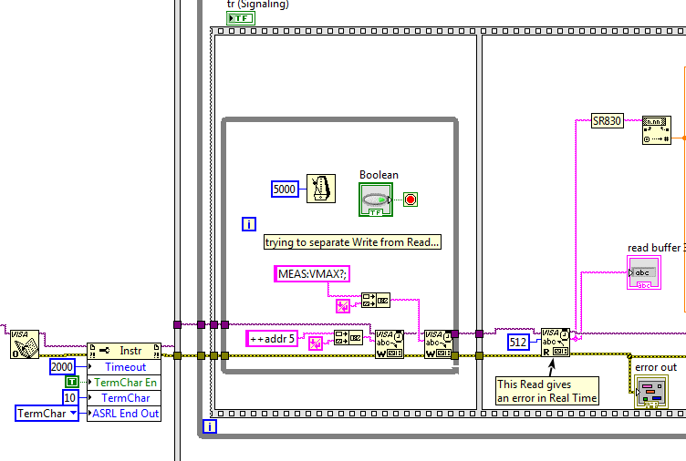
Read a signal scope works in execution to highlight, but not in real time
I want to get the maximum value of a waveform to a former stretch of Agilent 54622 via GPIB.
The problem is that I regularly receive a Visa Read error-1073807339 ("timeout expired before the operation is completed") when running in real time, but NEVER in execution to highlight mode.
The posts here suggests that the calendar can cause the read to run before writing was able to finish. So, I used one - manually controlled while loop, sequence and blocks waiting for try and ultra Structure separated blocks of reading and writing of overlap between them. But it still does not work!
Suggestions, please? (Thanks!)
If you happen to open the VI I attached, you will see that I use a serial port. This is because I use a USB of Prologix-GPIB adapter to interface with the scope (I don't have an adapter USB of NOR-GPIB). I used successfully this Prologix adapter for over 2 years to connect perfectly with an amplifier to locking SR830 and several other devices, so I don't think that's the problem...
What you need is the magic behind fairy!

-
Silverlight will not install on my computer. I get an error code 659. Silverlight has worked on computer at the same time. Vista in Home Office business management. Can someone help me with this issue? I installed Vista service pack 2.
johncoxcpa,
Well looking at the log you've posted, I came across this article:
MSI (s) (2 c: D4) [22:29:29:073]: sequence number number for this installation system restore.
This installation is forbidden by system policy. Contact your system administrator.
c:\c17e5b6672c37d9f685b\Silverlight.msiSo it seems that if your system has a software restriction policy installs. You need to contact your IT Department. to learn about the changes to the policy will be to install Silverlight.
Mike - Engineer Support Microsoft Answers
Visit our Microsoft answers feedback Forum and let us know what you think. -
Vista and the need for a kind of wide equalization system in real time for audio... and this driver seems to provide what I need... but will it work on my microsoft Driver card hd audio? If it is not possible, then what program could I use for an equalizer?
Hello
What is the model number of your sound card?
The drivers are specific to a device. RealTek drivers don't work for its Microsoft Map, you must install the correct driver for your device package works very well.
For more information about the driver, see the links below
Updated a hardware driver that is not working properly
Update drivers: recommended links
http://Windows.Microsoft.com/en-us/Windows-Vista/update-drivers-recommended-linksEqualizer you can see link below, also look on the internet for software that can help you in this task.
Change bass, stereo, and other audio effects in Windows Media Player
Note: Using third-party software, including hardware drivers can cause serious problems that may prevent your computer from starting properly. Microsoft cannot guarantee that problems resulting from the use of third-party software can be solved. Software using third party is at your own risk.
-
can not turn on real-time scanning 0x8000705b4 error code
got fed up with Mcafee so I removed the product with the programs and features and then used their cleaning cleaning tool Development than anything flying over. When I try to turn on real-time scanning, I get the 0x8000705b4 error code. The defender service is running. I have windows 8.
I decided to solve the problem by setting another disorder, that I'd been procrastinating. I've migrated my operating system on an SSD and could not be upgraded to win 8.1. A little research revealed that I was not the only 1 with this disorder. In any case, a clean install of win 8.0 followed to upgrade to win the 8.1 and the problem disappeared. Thanks for your help.
-
display of the work plan in real time for mobile devices?
I do my design in illustrator before exporting all the assets for use in mobile applications. Is there a way to get the work plan to display on my mobile device in real time? As it is now, I have to save the artboard as an image and put it on my phone to see what it looks like.
Hi Mike,.
The answer would be 'no', at the present time. You are already one of the workarounds.
Thank you
OM
Maybe you are looking for
-
When I try to download an app I get 503: Service unavailable
Does anyone else know issues with the App store? I can't download anything on my iPhone or iPad. iPhone is not giving me an error but simply to don't download. My mac give me a 503 error code when I try to download something. What is my account or ot
-
Satellite M30X-181 - turn to take more than 20 minutes
Hello.Laptop after pushing power button, take 20 minute to turn. Screen do not recognize worms upwards of 10 minutes, no part of the disk (one blink from HDD LED). Maybe someone saw in this problem? Post edited by: micha26
-
Driver update for Satellite 5100 503 with NVIDIA geforce4 440 Go
Hello there,It is a German call...I need an update of the graphics driver to a computer laptop toshiba satellite 5100 503, the nvidia geforce4 440 Go, that you can't get on the nvidia site, where have no mobile system to get.My laptop is quite slow.
-
sercurity Windows Update error code 80072F78 failure help under attack
I cannot download the updates of windows important sercurity, 11 updates, windows vista 6 windows defender 1 office 2007 4, displays error code 80072F78, cannot find a solution need help my computor get daily attacks.
-
How to download real repots of IPCC in time?
Hello I use express and improved edition of the IPCC. I wanted to know how to export reports in real time to Microsoft Excel or how to download these reports to save it in a video image? Thanks in advance.