communication with DAQmx SCXI
Hello
I have a problem to connect with a SCXI-1540 module.
In MAX, I see the module, and I put the "data area" a task NEITHER-DAQmx to reed the voltage on the input.
I see a standard value of 5, 38V even if I change the entry.
I missed a setting?
Tags: NI Hardware
Similar Questions
-
Checking the status of communication with NI DAQmx or NI6143
Hello world
I'm working on checking the status of communication with NI DAQmx or NI6143 in Microsoft Visual Studio 6.0 C++ on Windows XP. The communication situation is checked between the DLL and the NOR-DAQmx/NI6143. I wonder what is the command for the control of communication for NI DAQmx or NI6143, and if there is no code available. Any suggestion or advice is greatly appreciated.Thanks in advance.
There are many examples available on your computer that install with NI DAQmx. For examples in C/C++, follow the steps listed in this white paper:
http://www.NI.com/white-paper/6999/en
If you are new to data acquisition, that I suggest using LabVIEW. LabVIEW has several examples to begin to use a data acquisition equipment. To find them, open LabVIEW and select help > find examples... > Input and Output material > DAQmx.
As a note of clarification, NI DAQmx is the driver used to communicate with your device (NI 6143). You do not communicate with OR-DAQmx itself, but use it to send commands and receive data from your device.
Cameron T
-
Read more http://zone.ni.com/devzone/cda/tut/p/id/3308 he says rather non-challantly that ' module PXI-2567 and SCXI-1167 can also be programmed using the functions of NOR-DAQmx DIO. "
Does that mean that what follows (simple example) would work with the SCXI-1167, installed in a SCXI-1001 chassis?
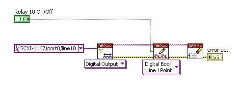
What happens if the SCXI-1167 was connected to the PC via the USB-1600 module? I'm inclined to think it WOULD because of the statement of the SCXI-1600 data sheet:
"The SCXI-1600 is a module of control for entry SCXI analog, analog output, digital i/o modulesand switching and full 16-bit digitizer."
Hello!
Please post on the Forums OR! I have configured material today and succescully executed the code you posted. So, you're right, it's possible!
-
My ipad 3 has stopped communicating with my airport extreme.
My ipad 3 has stopped communicating with my airport extreme. I rebooted, both so that made a network reset on the ipad. He sees the airport but does not connect. It will work on the personal hotspot on my phone.
Hello
If your ipad works with a hot spot that's the Aiirport is the problem
Go to the Apple Web site
support. Apple.com
You may need a software update for airport how old is this do you have another
Router, you can try?
See you soon
Brian
-
I installed and now have uninstalleda Applian program (freecorder I think) but find myself with a toolbar of community with a button leading to the theFreecorder help page. I don't want the additional toolbar or button. How can I get rid of him? I tried to remove and reinstall Firefox, but this has not done it.
Hello
Please try to go to Tools (or Alt + T) > modules, Extensions , click on the left and if it is listed on the right, delete it. Otherwise, you will need to go to Add/Remove Programs in the Control Panel of BONE and remove it from there.
-
Timing embedded with Daqmx on PCI-6132
Hello
My colleague and I are trying to make a program Labview which starts a timer when the first trigger (sensor) is struck and stop the timer when the second trigger (sensor) is reached in 2012. We currently have a program for her, but this program was not sufficiently precise. Also the current program is using the DAQ assistant, but we would like to replace with daqmx triggering. We have also tried to use the OnboardClock on the PCI-6132, but still could not do the work programme.
Is there anyone who knows how to do this and could explain it?
(In the attachment is the current program)
Thanks in advance,
Tommy van Geest
Hello Tommy.
You can share your current code?
-
DASYLab is not communicating with the hardware dbk25a3
Hello:
I'm trying to troubleshoot a high pressure processing equipment. This system uses a PID controller. The level of pressure does not stop at the set point, but continue to increase. I am trying to solve this problem. As the program was written by someone else and there is no documentation on what each represent module and done. It is very difficult for me to solve the problems. Therefore, I decided to start all over again with my own module. However, I have a problem. My hardware (DBK25 and others) is not communicating with the module of Dasylab. I tried several different things, that nothing seemed to work. I get this error.
DBK25A3
 O
OAn entry of a module is open.
Any help is highly appreciated
Thank you
Krishna
The error message indicates that you have a module that has one input open - nothing is connected. You must have a data wire to all entries.
-
With a sampling of the data with DAQMX, error-200279 occurs when making 2d array dbl
Hello
I did a system of simple analog voltage with DAQMX data acquisition.
It is made for reading of capacitance, where output capacitance value out of a circuit in the periodic voltage signal.
What I want is to get data from four capacitors simultaneously through four channels, using samples n n (dbl 2d).
The structure of my VI is almost similar with examples of continuous sampling of voltage in LabView, with the exception of a few other calculations in the loop.
And for the synchronization of the trigger, I've corrected the edge of release with the external signal from the capacitance reading circuit.
Version no. 1 has a channel for data input voltage. Version n ° 2 has four channels for the input data.
While ver.1 can get accurate reading of four capacitors circuit data each (a single channel at a time),.
ver.2 acquires four channels of data, with a single thin data channel, all the others were wrong.
I saw a 200279 error occur in the DAQMX read part 2d dbl, so I tried increasing the buffers by changing the sampling frequency or the number of samples, but it wasn't everything.
I rose for most of the forums with the 200279 error, but the solution would not work on mine.
Anyone can find the problem? I will attach my screws it may include a bit of Korean language, but most of them are in English, shouldn't be too hard to recognize. Sorry for the inconvenience.
Oh I forgot, my DAQ is NI USB-6259, and it works in Win XP sp3 and LabView 8.6.
Thank you.
Hello Azurenight,
The 6259 is a DAQ card of the M Series Multiplexed, which means that it is not possible to sample each signal at the same instant, rather the channels are all sent through the ADC even and must be sampled in order. More information on this can be found here:
LabVIEW Help: Multiplexing compared with simultaneous sampling
http://zone.NI.com/reference/en-XX/help/370466W-01/mxcncpts/multisimulsamp/
It may still be possible to get the data you need with the card you have - could you give more information about the maximum eligible period between samples on different channels?
If you require * real * simultaneous sampling, you will probably need different hardware.
Kind regards
-
SPI Communication with PIC24HJ256GP210
Hello
I need make the SPI Communication with hardware PIC24HJ256GP210 in LabVIEW 2010 with NI USB 8451.I want to send 8 bytes data and receive data of 8 bytes of PIC. I'll send data byte-by-byte change the signal of the chip Select (CS). Before you send the data I will send ENQ (mark 3A) to check the status PIC, then after receiving ACK (Acknowledge as A1), I will send the data packet.
My test procedure indicated below,
- Setting clock polarity at zero (LOW idle), a second Edge clock Phase) and the clock frequency of 1 MHz to device NI USB-8451
- 3 sending data (ENQ) and followed meaningless data byte by byte, also change state Chip Select
- No explicit deadline has provided since the sending of the API takes 20msec to run
- Receive the acknowledgment of receipt (A1) of the sensor
- Send DataPacket [Eg: A5, 03, 02, 00, 00, A6, 2 c, DD] byte by byte, also changing chip select signal
- No explicit delay gave between each byte from API takes 20msec to perform sending
- Send 8 bytes , which means less data byte-by-byte, and receive byte-by-byte data PEAK
- Received all of the data of 8 bytes with an incorrect value
If please review my test procedure and give your comments if you have worked with SPI or if you have any input for my query.
Thanks in advance.
Note: Tie my code with this mail for your reference.
Kind regards
Nicolas.
Hello O_Proulx,
Thanks for your reply.
Communication SPI after sending the data we send again meaningless bytes, which equals how many bytes we would like to receive the answer System.So we cannot read the data in the same VI as you mentioned in the code.
My problem has been resolved. Byte meaningless, I need to send the file HEX .beacuse 'AB' has been developed in this way.
Kind regards
Nicolas.
-
RS 232 communication with a projector
Hello! I work in communication with my prjector. The controls are pretty simple, just PWR it for OFF\r PWR to turn off and LAMP? How many hours have the lamp worked \r to land the aircraft. So I just used the example of the writing/reading series with labview, but had a few problems.
1º) it works but it keeps giving me an error, I can't handle. Is the current operation of visa wait time. I tried it here and all the people say something on the lines of commands, but I put them and set up in the port, so I don't really know how to handle this error. Another thing, it is how can I put \r or 0xD for my end of just the default write command?
2º) how can I make my request just be an exe that you don't have to press ' EXECUTE ' always to use it?
3º) my last question is to ask questions about how to manage this thing, I need to read used with the control LAMP lamp hours?, and projector will answer me with something like: LAMP = xxx. How to handle this response to send it via TCP/IP? Should I have to create a new variable or something? I mean, I just need with another application in order to power switch of the projector via tcp/ip and calling hours of lamps via TCP/IP, so I don't really know how to handle. Thanks for all the peoples and let me know if you need more information, I'm not native English sorry for my mistakes.
Edit: I forgot to put my vi.
1. you will obviously get a timeout when you send the commands that do not generate a frequency of the instrument. Only do a reading when you send the LAMP? interview and to automatically send \r, set the stop to "0 D" character.
2. you have the app Builder to create an exe file. In order to make the VI automatically running, go to the properties of VI > execution and check "run then '.
3. I do not understand. First, you talk about RS - 232 and now you want to convert this TCP/IP communication VI?
-
set up a placeholder or virtual DAQmx SCXI task?
is it possible to implement a task DAQmx SCXI without having any SCXI hardware? I don't have access to the material and I was wondering if I could create a "virtual task' for my SCXI program before gettting the material?
Thank you!
Yes. Go to measure Automation Explorer. Devices and Interfaces, do a right click, create new ones... You can then select Virtual Instrument or NOR-DAQmx simulated device.
-
Problem with getting communication with old instrument GPIB-ENET/100
Hello!
I'm trying to get my program in VB.net to communicate with an older instrument (Infratek 305 A, measure of power) via a GPIB-ENET/100 device.
The manual of the instrument does not say what GPIB standard, it supports, but the instrument is detected by the measurement and Automation Explorer.
Detected by that I mean that MAE has detected an instrument located on the right GPIB address, but indicated identification is the output measure instrument string
instead of the name of instrument (as shown for some more recent instruments of Agilent).
When I run my application, I followed the communication with NISpy.
Configuration of the device seems to work and I present only once in the program.
The problem is reading data from the instrument. Whenever I read the data, I get a correct string of the instrument. But the problem is
I get the same data in two consecutive and all readings first after that I get new data and also these new data are received in two consecutive readings.
According to the manual of the instrument the instrument generates the data as follows:
"A row of data ends with CRLF. The instrument can send multiple rows of data. "When all of the data transfer is complete the EOI (end or identify) is sent.
My endpoint settings are:
Send EOI to write complete: YES
Terminate read on EOS: No.
EOS byte: 2
8 bit EOS compare: YES
Define EOI with EOS on write: No.
How can I configure the GPIB-ENET/100 to work with my instrument?
Here are som NISpy logs:
# Configuration #.
61 ibwrt(UD3, "C0C2C4C8..", 10 (0xA))
PID: 0x0000113C Thread ID: 0x000008B4
Departure time: 13:54:43.671 call duration 00:00:00.079
ibsta: 0 x 100 iberr: 0 ibcntl: 10 (0xa)62 ThreadIbcntl()
PID: 0x0000113C Thread ID: 0x000008B4
Departure time: 13:54:43.750 call duration 00:00:00.000
ibsta: 0 x 100 iberr: 0 ibcntl: 10 (0xa)63 ibwrt(UD3, "K0K3K5K9..", 10 (0xA))
PID: 0x0000113C Thread ID: 0x000008B4
Departure time: 13:54:43.765 call duration 00:00:00.125
ibsta: 0 x 100 iberr: 0 ibcntl: 10 (0xa)64 ThreadIbcntl()
PID: 0x0000113C Thread ID: 0x000008B4
Departure time: 13:54:43.890 call duration 00:00:00.000
ibsta: 0 x 100 iberr: 0 ibcntl: 10 (0xa)65 ibwrt(UD3, "F14F18F24..", 11 (0xB))
PID: 0x0000113C Thread ID: 0x000008B4
Departure time: 13:54:43.890 call duration 00:00:09.250
ibsta: 0 x 100 iberr: 0 ibcntl: 11 (0xb)66 ThreadIbcntl()
PID: 0x0000113C Thread ID: 0x000008B4
Departure time: 13:54:53.140 call duration 00:00:00.000
ibsta: 0 x 100 iberr: 0 ibcntl: 11 (0xb)### LU ###
437 ibrd(UD3, "*AC/1.0A480V/...", 1024 (0x400))
PID: 0x0000113C Thread ID: 0x000008B4
Departure time: 13:58:52.484 call duration 00:00:00.094
ibsta: 0 x 2100 iberr: 0 ibcntl: 225 (0xe1)438 ThreadIbcntl()
PID: 0x0000113C Thread ID: 0x000008B4
Departure time: 13:58:52.578 call duration 00:00:00.000
ibsta: 0 x 2100 iberr: 0 ibcntl: 225 (0xe1)439 ThreadIbcntl()
PID: 0x0000113C Thread ID: 0x000008B4
Departure time: 13:58:52.578 call duration 00:00:00.000
ibsta: 0 x 2100 iberr: 0 ibcntl: 225 (0xe1)Hello!
I don't have the opportunity to test with other controllers.
However, I found a solution to my problem.
The instrument should output 4 lines of data.
L1 - line with comments
L2 - line with current values
L3 - line with the values of voltage
L4 - line with power values
The first line of the reading stops the instrument of implementation of additional measures.
The measurements in the instrument began reading the last line of data (L4)
The problem was that the instrument for a reason any also released a fifth line, which was empty.
Read this line 5' th stopped the instrument again.
By configuring the HW to finish reading on EOS, with EOS PMQS, the value byte, I could read the
buffer of the instrument with a line output instead. This way I could read just L1 - L4
and the instrument could work again.
Next time I should read data from the Instr. first of all, I would like to read the empty line, then
L1 - L4.
Why the outputs Instr. an additional empty line will be left not resolved.
My problem is solved.
-
Is it time stamp with daqmx read
Hi all
Simple question. I have currently not creating a task or starting a task, I simply create a channel and reading that chanel.
It is... Why I don't get a timestamp when you do and do I create a task to get one of this?
There is a timestamp when you use the DAQ Assistant or when you choose to return a data type of waveform with DAQmx Read.
You can't do a reading without a blemish. You don't have to create the task in MAX, however.
-
Hello
I am currently working on a Senior design project where I have to measure rpm, torque, pressure and temperature. I use strain gauges, pressure sensor and a Hall effect sensor, thermocouples for these readings. A myDAQ collects readings rpm and pressure while a cDAQ collects couple and readings of the temperature with NI 9211 and NI 9237 modules. I have created LabVIEW screws for each sensor and they work. The problem I have is when I try to create a VI with DAQmx who reads all the values of these sensors simultaneously. The VI I joined randomly displays one of the measures while other measures remain empty. How can I change my VI so I can show all my readings at the same time?
Yes. Create multiple tasks, where all the strings that are common to a specific device are grouped in the same task. Then go and run these tasks in parallel. Do you need a precise synchronization between the tracks in the different devices? If this isn't the case, then the method should work perfectly. If you need a precise timing, things would get more complicated, but might not be impossible.
-
Hello
How can I set the time of liberation with DAQmx?
In general, with a single DAQ hardware, the two signals are connected at the same time and the acquisition time is a function of the sampling frequency and number of samples read. For example, with a sampling rate of 1000 samples/s and 50 samples, the acquisition will be 50 msec. You then get a returned array if you wanted to watch a single signal by iteration of the while loop, it is simply a matter of indexing the specific channel to the table. You must set the mode of continuous sampling to avoid gaps and precise timing. Using two separate tasks and switching back and forth would add a lot of overhead to close/create tasks and you have little control over this period.
Maybe you are looking for
-
27 "+ monitor of type C in the United Kingdom?"
Afternoon, Recently I've been looking for a more tidy installation my Mac Book Pro 15 "(rétine fin 2013)." I have the henge horizontal dock now, but my laptop constantly get hot (fan will nut) and when I run the mac and 2 external performance of the
-
How to preserve "sorting" of a photo album, when I make a shared album iCloud? All my work sort of creatively, is lost when the online album sharing. Maybe I should use DropBox instead? Thank you. Rog Mason
-
Hello world I'm new to the forum and I have a question... my Pavilion DV7 Notebook PC audio editing Beats screen has a crack inside and I am looking for a replacement screen, but I want to make sure I get the correct replacement screen. I have i7 2.3
-
Downloading pictures from a phone
How to download a picture of my Net10 phone on my computer?
-
See tittle for the description of the problem. Why can you give us a service pack that some many people have trouble installing? Its stupid. Wasted my time and yours. Please help with this and post the fix so that others don't have to go through