Comparison of c sharp and Labview?
Can any budy tell me the comparison between C sharp, dot Net and Labview on Non Application of material?
Please tell me the positive and negative on all three.
Its Urgent
Concerning
Gilles
Your question is too vague. And besides, there is no need to compare c# to .NET. C# is a language that uses .NET. .NET is a framework, not a programming language. Your question might as well ask "can you tell me the comparison between C++ (version not .NET) and LabVIEW?
There has been discussions numeous on comparison of LabVIEW with the text-based programs. Please do a search before asking such a vague question.
How to ask Questions the Smart way
Tags: NI Software
Similar Questions
-
What are the differences between LabVIEW and LabVIEW FPGA and LabVIEW RT
I need a comparison of LabVIEW, LabVIEW FPGA, and LabVIEW RT
Sorry, I misunderstood.
LabVIEW RT (LabVIEW Real-time) combines graphical LabVIEW of programming with the power of a real-time operating system, allowing you to create applications in real time.
-
I have a problem with the simulation in Matlab 6.5 and LabVIEW for PID controllers
I have a problem with the simulation in Matlab 6.5 and LabVIEW. I have a few methods for granting regulators PID in MATLAB to go but not of LabVIEW. Degree of international teams of two transfer but when I passed to the fourth degree is no longer working. We have changed the formula to calculate the parameters for the fourth year and gave me some good values for assignment of Matlab, but when I put on LabVIEW are not resolved. the formulas are available in PDF format and are. Please help me and me someone if possible. Thank you
Lim.4 generation in comparison methods and the MATLAB program settings are for the service of transfer to the second degree.Hello Lascarica,
I noticed that you are using the screw of PID. Gains on these screws are based on TIME instead of GAIN. You should be able to build a PID regulator and vary the gains and then compare the results.
-
NOR-Fieldpoint supported in Windows 7 and LabView 8.6
We have a 'classic' with an ethernet controller FieldPoint system. We want to be able to read/write from/to the FieldPoint network using a computer with LabView 8.6 and Windows 7. NOR-FieldPoint is supported in LabView 8.6 and Windows 7?
Kind regards
Nate
Hi natewkidd,
I feel like some confusion between the operating systems running on a development computer (as Windows 7) and real-time operating systems that run on our real time (such as the PS-2000) controllers. I will do my best to clear up this confusion first answering your questions.
(1) what is the difference between 2009 LabView real-time and LabView 2009?
LabVIEW Real-time 2009 is actually a software officially known as 2009 LabVIEW Real-time which is installed after the LabVIEW 2009 development software to allow the user to develop and deploy applications in real time on targets in real time as your PS-2000. You can consider the LabVIEW Real-time 2009 almost as a plug-in for LabVIEW 2009 deployment and development of real-time applications.
(2) if I have a PS-2000 on the ethernet network and to use a computer that is running Windows 7 and LabView 2009 for record and display data, will I still be able to communicate with the network FieldPoint screws write FieldPoint to my Windows 7 computer?
If you go just to use the PS-2000 as a network module (NOT to deploy a real-time application to run on the PS 2000 itself), you should be able to communicate with him using just the read/write FieldPoint screw on your Windows 7 with LabVIEW 2009 machine and the driver NOR-FieldPoint 6.0.5. In this case, you actually do not need the Module Time since you do not deploy the application to the target in real time.
About the PS-2000 unsupported beyond LabVIEW 8.5.1, is because the controller's memory is not large enough to hold the software that is installed on the controller with LabVIEW 8.6.x Module real-time and LabVIEW Real-time Module 2009. For more information on this, you can check this knowledge base article.
I hope it's useful! Let me know if you have any other questions.
Thanks for choosing National instruments.
Aaron Peña
National Instruments
Technical sales engineer
-
How to measure the angular velocity, the angle and trigger using a gyroscopic sensor breakout board and LabView data acquisition?
There is a single channel data acquisition code which measures the angular velocity, angle and flexibility using a gyroscopic sensor breakout board and acquisition of LabView data attached to this, I need a help to creat two-channel data acquisition code?
Hello
Attached is a vi that you can use in order to read the measured angular position of an encoder.
If you need more examples on the tasks that you can develop with NOR-DAQmx and LabVIEW, you just need to open LabVIEW and click Help > find examples > Input and Output material > DAQmx > entry counter.
Kind regards
-
Compatibility of boards of daughter BasicTx and BasicRx with USRP2920 and LabView
I want to know that girls BasicTx and Rx cards Ettus research base are compatible with USRP2920 and Labview or not.
These cards also supports variable gain or not? Please confirm
Thank you
JK
They will work, but you must use property nodes to configure them. No is no LO so ther is no center frequency setting. I and Q are separate channels so you must separate them and treat them as such. There are no gain as the boards primarily provide access to the ADC.
-
How to sit interface with matlab 2010A and labview 2010
I use tools of simulation interface 5.0 with matlab 2010A and labview 2010, I want to take my cue from matlab, labview but signal transfer, I am facing a problem. I want to know is there any compatibility issue in sit 5.0 or I do something wrong?
photos of errors are attached.natasftw wrote:
http://digital.NI.com/public.nsf/allkb/02F5FA55FC28BDE1862578A30071F975
While it is for 2011, I doubt that they decided to remove 64-bit compatibility as they went forward as 64-bit has become more rather than less demand. In this document,notes LabVIEW Simulation Interface Toolkit does not support 64 bit versions of MATLAB application software."The extent of the compatiblitly for 32 - bit, I'd take a peek at: http://digital.ni.com/public.nsf/allkb/D174674A91E5536286257428005C2426
The OP's question was SIT support 64 - bit version of LabVIEW and 64-bit version of the MATLAB/Simulink itself, not the operating system software.
Document in your second link is on a completely different topic to have API for LabVIEW and MATLAB/Simulink/RTW (well, mostly Simulink & RTW). Here is the relevant link for the 32-bit compatibility: http://digital.ni.com/public.nsf/allkb/049295038FF0EE2A86257A06006B2DAD is no SIT 64-bit.
Other underlying issues is that Pharlap does not have a 64-bit version. Finally, simulations are better performed on some RTOS (embedded PXI) for a deterministic execution rather than PC operating systems.
-BTC
-
Hide icon Label step using the API Testand and LabVIEW
Hello
can someone tell me how it is possible to hide the icon of a step label using the API Testand and LabVIEW?
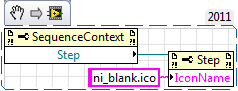
In the Teststand sequence editor, under the Label Edit tab there is a checkbox called "Hide icon". Is there something similar in the API?
Thank you
Yes you can, you must set the stage "ni_blank.ico" IconName property
-
Linear actuator, motor controller and labview. Establishing a connection.
Overview:
I have a 12VDC linear actuator (potentiometer built in) connected to the and 21v3 Jrk USB motor with Feedback Controller (http://www.pololu.com/catalog/product/1392). Feedback from the actuator wires connect to the motor controller motor USB controller connects to the computer via USB.Problem:
Establish the connection between the motor controller and labview.What I've done so far:
I installed the drivers for the motor controller and windows detects it. OR MAX detects my motor controller (photo attached), but for some reason when I try to access it via the daq assistant in labview is not see it. I tried also access it through VISA with no result...
Help will be appreciated.
Thank you
Peter
You have some things you have to look in:
- When you have installed the software, he was installing a USB > dll Com Port virtual as FTDIchip or similar? If so, when connect you your device, it will reveal itself as a normal COM (new) Port in Device Manager. You then try to talk to this COM port.
- If you try to use the USB native on the map (as MAX has detected for you), then you will need to use the code in the .NET framework provided by the manufacturer (probably written in c#) and do your own builders in LabVIEW. If you have never done this before, it's not trivial.
I would call the manufacturer and just tell them what you're trying to do. They have probably treated before LabVIEW and can have an example to help you get started.
Edit: for fun, I followed the link you provided (which doesn't really). I searched "LabVIEW" of their site and indeed has achieved several successes. There is one thing that I downloaded (can't resist looking at code) was a gigantic turd. However, it doesn't use a standard Com port.
-
Implement and control 'meter' in S7 - 300 by the OPC and LabVIEW
Hello world
I use a S7-300 PLC and OPC Server for my projects. I have a problem: S7 - 300 has a meter module which digital signal of County. I only can implemented using SIMATIC STEP 7. Can I set up the meter module using only the server OPC and LabVIEW
does anyone have a solution or an idea for my problem?
could you please help me...
Thank you
Hi Echion,
NOR-DAQ (MX) is used only for material OR: no you can not use it.
To program the controller you must use the right programming environment. For Siemens S7, you need to use Simatic (or perhaps some other 3rd party software supporting IEC61131). Point.
The OPC server is used only for the exchange of data. This is no interface programming!
-
LCD, extented and Labview controls
Hello
I use a LCD series (https://www.sparkfun.com/products/9395) associated with a TTL - USB converter (http://www.miniinthebox.com/fr/cp2102-usb-2-0-vers-uart-ttl-convertisseur-6pin-serie-du-module_p3910... and labview with VI No. 1.) Sending simple commands such as VI No. 1 works well. My problem is that I do not know how to send orders Extended Page 2 here https://www.sparkfun.com/datasheets/LCD/SerLCD_V2_5.PDF.
For example, as I understand the datasheet, I need to send 124 128 to disable the brightness of the screen. If I type "124 128" in VI n ° 1 the LCD displays "124128. I get the same result with VI n ° 2.
If anyone know what I can try next?
Thanks a lot.
User1979
It seems that these values (124 and 128) are the decimal equivalent of the byte to transmit 0x7C and 0x80. It is not possible to say with certainty from your images, but most likely you send the characters of ASCII text for '1' '2' '4' and '1' '2' '8 '. Since then, they appear on the screen that is certainly what is happening.
In your second pop VI on the string constants and select hexadecimal display in the context menu. Then type the values hex 7 c and 80.
Lynn
-
I'm doing a Shell call Firefox in the directory C:\Program Files (x 86) of \Mozilla FireFox\ and LabView shell call gives an error. I can go to the BACK shell and make the fine call, but Labview Shell gives several errors. Anyone know how to get around the problem of directory with the name of the Program Files (x 86) directory with space and the (x 86) BACK doesn't seem to like?
You must use quotation marks.
-
Limitations of memory PNRF and LabVIEW
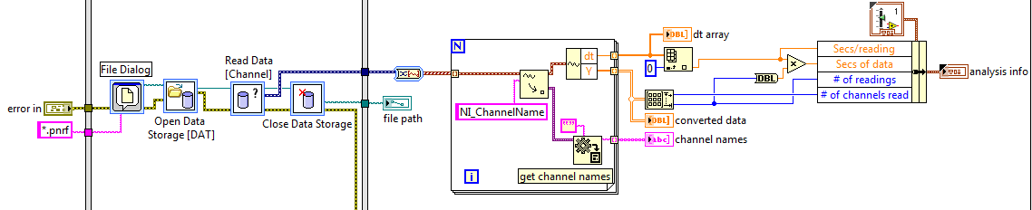
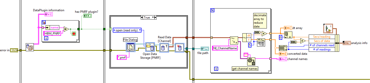
I've written a VI that reads a data PNRF file (using the data of LabVIEW PNRF plugin) and takes the data from the channels, sampling rate and channel names. However, I am limited to playback the files having no more than 8 channels, 2 370 000 readings in each channel. Nothing more and LabVIEW gives me an error of low memory on a Windows 7 Pro 32-bit computer that has 4 GB of RAM. Using the task, LabVIEW-error with use of memory manager in 1 063 216 KB.
Is there a better way to read files more PNRF?
The VI looks like this:
Thank you
Ron
Update: I've improved time (1/4) and the parameters of memory (1/2) by changing the 'chain of output data' property service 'Read data [channel]' in 'table of waveforms.
-
Can someone tell me how to connect with an instrument using the KUSB - 488 A converter USB to GPIB and LABVIEW?
My question is that if we have equipped a GPIB card on computer LABVIEW to recognize and display the address of cards... When I connect the USB-GPIB converter without this interface appears. So, how to treat the instrument? using VISA? Please give a simple example...Thank you
-
BNC-2110, 6023E PCI card and Labview V9.0: sensitivity of data acquisition (change more little detectable voltage) is 0.002V
Hi, I use the software/hardware above to read a voltage of a potentiostat world Precision Instruments No..
I'm trying to record changes in voltage as low as 0.0003V but using the wizard DAQ, I seem to be limited to a sensitivity of 0.002V. This is the limit of real sensitivity or have I missed something?
Any help would be greatly appreciated.
Hi DCAM77,
Thanks for joining the forums!

The PCI or 6023E has a 12-bit ADC. In other words, it can make the difference between 4096 (2 ^ 12) different levels within the range of cards. The card you have has a selectable range by ± 10 V, ± 5 V, ± 500 mV or ±50 mV software.
This means that the minimum detectable variation will be 4 mV, 20 mV, 244 µV or 24, depending on the chosen range µV.
You should be able to use the ± 500 mV or ±50 mV to get the least significant bit (LSB) value, you need, even if it means that your signal is located between these values. If not, then you need to consider other materials to the application, or the addition of external circuits across the signal.
Maybe you are looking for
-
Talk to the text sent by 'null '.
When I try and talk to the text of my husband, it continues to send "null" while Siri said she looks and she is sending. It works with my two other friends who have iPhones. Suggestions? I already turned my phone market.
-
How can I deactivate Do not track? He has my computer messed up.
Once I enabled do not track, I had to connect to everything, and I can't seem to work.
-
Spectrum of 13-4109na x 360 HP: question for HP spectrum 13-4109na x 360 Ram upgrade
Hello I am looking to buy new spectrum 13-4109na x 360 HP and I would like to know if it would be possible to increase the 16 GB ram? The product technique (https://store.hp.com/UKStore/Merch/Product.aspx?id=P5P13EA & opt = ABU & salt = NTB #merch -
-
Hello I want to generate a vector that is the cumulative sum of another vector without using a loop. My vector is more than 10 ^ 6 length and a loop takes forever. I use cumsum in matlab, but could not find something similar in labview. Thank you!
-
I bought my scanner a few years ago, I had a program that I think came with it. I don't remember the name, but when I wanted something scam, I open this program and adjust the settings, press scan in the program window, not on the scanner. This pro