Conflict of the PXI-8461
Hi all
I'll put up a PXI module which, like a BOX of cards in a chassis PXI-1042 (PXI-8461) by using a controller PX-8360. I also have a PCI CAN map at the back of the PC that I use.
There seems to be a conflict - can someone help me please?
Concerning
Dave
PS I have recently updated to LabView2009 and also have installed 2.6.2 CAN
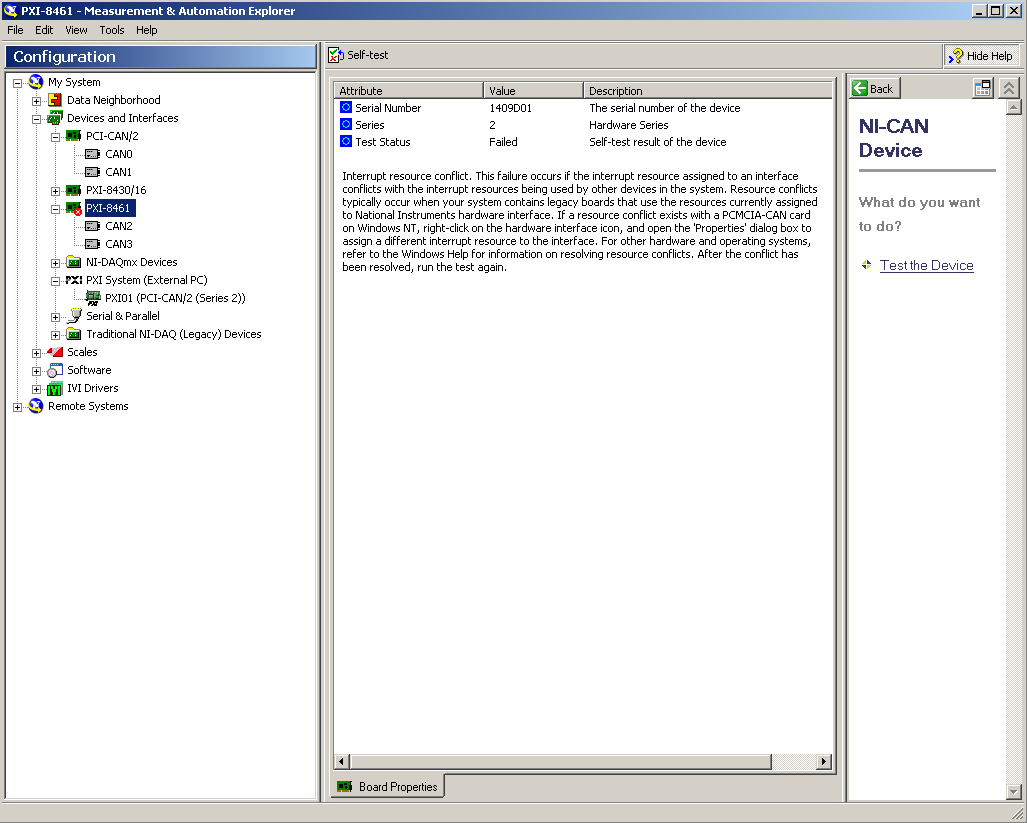
Hi all
DeltaJ came through a call to support with the same question. In the interest of everyone in the community, the problem has been resolved by simply moving around some of the modules in the chassis. Resource conflicts can often be solved this way.
Best wishes
Tags: NI Hardware
Similar Questions
-
The PXI-8512 does support the series 2 filter or a similar mechanism to filter the messages?
Hello
I need to buy a couple of cards CAN interfaces for my test application and I wonder what you choose
I already used a PXI-8461 to obtain data of the customer model under test, and due to the fact that sometimes the client bus can be very busy, but most of the messages is not interesting for my system that I use currently series 2 comparator/mask/filter to filter only the interesting messages.
Without this filter, the PXI-8461 often returns an error due to overloading of the bus. With the filter, everything works perfectly
Now I need to implement several testbeds with this same feature, and I plan to move to the new PXI-8512 for new.
My question is: is the most recent PXI-8512 a device series 2 institutions? Support the filter 2 series or any other mechanism to avoid problems on the busy bus?
Thank you for your support.
Kind regards
Davide
Hi Davide.
the PXI-8512 isn't a series 2 device. The PXI-8512 is a device of the X-NET family. X-NET is the technology whose use OR in support of CAN, LIN and FlexRay with a driver API. Series 2 devices use the former NI-CAN driver that only supports the CAN. All of the new devices are devices X-NET.
Take a look to the following document:
NI-CAN for NOR-XNET application migration
http://www.NI.com/white-paper/9717/enOn this page you will find the following statement for the function that you are already using:
Transceiver filters were traditionally indicated for applications where only a few CAN IDs have been considered on a bus high load. In some cases, material NI-CAN support the bandwidth of the full bus, which leads to a buffer overflow. The hardware architecture OR XNET uses the engine NOR-XNET DMA-driven to eliminate the occurrence of buffer overflows. CAN of NOR-XNET interfaces are able to handle high load bus and transmitting at the maximum rate without coupling to buffer overrun. If your applications use the hardware filters extensively, NOR recommend setting up CAN opposes, or by reading the bus while using Network Interface objects. The best option for these applications is to modify your code to use the API OR-XNET native.
Best regards, Stephan
-
Why does take so long to clear a task (with the DMA transfer) using the PXI bus?
I am migrating from a system that has the habit of using a PCI-6133 (8 channels HAVE simultaneous) and PCI-6733 (8 channels AO) to one that uses a PXI-6133 and PXI-6733 mounted in a PXI-1033 chassis.
In general, things seem to be working (synchronized I / AO to run near the maximum speed on both devices), with the exception that the compensation an AO task on the PXI-6733 takes always (the order of 20-30 seconds).
Even when I try the generation of the sine wave for the PXI-6733 in MAX test Panel, it takes the same amount of time to stop the task. If I switch to the use of interrupts as transfer mechanism, it stops immediately.
I tried to use the transfer mechanism of interruption on my more demanding set of synchronized tasks, but that does not produce good behavior (even if he doesn't give any errors).
Is there a trick (or the best diagnosis) to help get my tasks working with DMA under PXI that worked very well on PCI?
Thanks in advance!
Thank you, Patrick. I tried on another computer (Dell T5400) and everything worked as expected. I think that the problems I have experienced on the first computer were due to a conflict with a PXI driver for another card I have not installed during my tests (and which I did not know was PXI, but he appeared as a PXI device in M & A once I put it in it should have a kind of PCI - PXI bridge internal?). So ultimately, pure card / slot / pilot shenanigans and everything seems to be fine now.
-
Satellite R840 - 12 c - conflict with the RFBUS "Bluetooth."
My Toshiba Satellite R840 - 12 c has a problem with bluetooth.
On the Device Manager tab, I see a conflict with the RFBUS "Bluetooth."
So my bluetooth setting does not work... In other words my laptop cannot detect bluetooth despite being bluetooth devices "on"...> Tab in Device Manager, I see a conflict with the "Bluetooth RFBUS.
So uninstall the device first, then download the stack of BT from Toshiba BT portal and after reboot again install this new.
http://APS2.toshiba-tro.de/Bluetooth/ -
800 - 030qe envy: conflict with the new video card
I bought and installed an EVGA GEForce GTX960 graphics card and discovered a conflict with the SATA cable on the motherboard connector. EVGA has recommended that I find a SATA cable with a connector at right angles. Can anyone suggest a source for a suitable cable? Mine is red (?).
@bobsun2, welcome to the forum.
This is a cable that should work for you.
Please click on the button + Thumbs up if I helped you and click on accept as Solution If your problem is resolved.
-
Qosmio G30: Conflict between the audio driver Sigmatel and Vista SP1
Hello
I have a laptop Qosmio G30 PQG32E and impossible to move to Vista SP1 because the driver Sigmatel (6.10.5462.0) is in conflict with the service pack.
As some of you may know, there is no Sigmatel and IDT who bought them is so say nonexistent, saying to contact the OEM directly to drivers updated.Is there a plan to upgrade the audio driver?
There are huge memory leaks in my case from the audio driver.
If you use Photoshop or Premiere Pro, the audiodg.exe process consumes 800 MB and more after an hour of continuous work.I hope for an update driver stable and more stability of the SP1.
I am a dreamer?The problem is that the final version of Vista SP1 is brand new and it may happen that some drivers don't support this new service pack.
In this case the driver needs to be updated.If you will not find the latest version on the Toshiba page then maybe you can find it here:
http://www.IDT.com/?ID=3969
In any case, the solution is the update driver and sooner or later, the update will be available.
Good bye
-
OR DC Soft Front Panel, minorbug, small bug with the PXI-4110
Hello
The NI DC Soft Front Panel V14.0, with the PXI-4110, scrolling to negative tension, works as expected to-10V, but then returns to 0. If we change from - 1V procedure, it goes...-8-9,-10, -1, -2... instead of-8-9,-10, -11, -12...
Everything about her, a simple thing that I miss is a switch for all three voltages.
(Also, IMO, it would be logical for negative tensions with the arrow pointing down, not more).
My 2 c
Hello Janaf,
I completely agree with two of your statements, I tabled a report of corrective measures that you can monitor in the next versions of DCPower to see if this is fixed with the FPS. CAR number: 512257
I've added notes that only manual insertion of numbers - less than 10 works and that it was not logical to use arrow increment or upward arrow to reduce the output voltage.
-
What pins to use to receive the data from the PDS ELITE RS485 with the PXI-8431/2?
Hello!
I use the PXI-8431/2 to read data from the flow meter PDS ELITE (Modbus RTU). Receiving data, the RS485 protocol request to terminals 4 and 5, but this configuration does not seem to work. When I connect the RS-485 converter USB of Microflex I get the data correctly, so somehow between the PIN lay and PXI this problem there.
Can someone help me?
See you soon,.
Steven
Hello Steven,
I think that what was Hossein trying to send you is the following:
How to connect and configure a device with RS-485 2-wire
Can you also tell me a little more what you use to read the data? What environment. You have 2-wire or 4-wire Modbus RTU?
Kind regards
-
Variation of thermal EMF of the PXI-2530 modules
This message/question is a companion of my the most recent message in another thread.
In addition to watching some resistance higher than expected that affected current measurements using modules PXI-2530 multiplexer 4W topology, I saw systematic variation in track-to-track blood pressure measurements. Tensions would increase gradually through the 16 channels in a configuration by measuring the voltage at the terminals a resistor 1.5 kOhm with 0.5 au crossing (75 uV). I've identified that the thermal EMF of the reed in the PXI2530 module switches is on the same order of magnitude of these measures and set out to quantify the differences EMF thermal track-to-track between my three modules.
Test method: I have a TB-50 which is configured to mux the signals of tension for a DMM. I connected each of the four DB-50 one cable of 176 pins to this block and collected with a PXI-4071 pressure readings set to 7.5 digits precision in the range of 100 mV and > 10 GOhm impedance. For most channels, it took several minutes for the voltage stabilize - or at least appear that it was to stabilize.
I enclose three graphs. Note that the vertical scale is the same on each.
Data that triggered this survey was collected with MUX1, via connector P2 to voltage. The magnitude was not quite the same-probably related to the phenomenon of stabilization time, but obviously the worst group of channels three multiplexer modules.
The three modules were all bought at the same time (about 2 years ago), but had only limited its use in the first year or more. The three now have various 'mileage' based on my use. But MUX1 clearly behaves differently two other modules. The
I changed my test conditions to spend 0.5 au via a higher resistance to thermal EMF less important. The PXI-2530 sheets indicate that thermal EMF must be less than 50 uV. In most of my measurements, it is. But not for MUX1!
Any thoughts?
Thank you
Jeff
Hi Jeff,
You can check that all the three modules are PXI-2530, not PXI-2530 b (while, as the PXI-2530 b parts slightly higher thermal emf)?
Specification of emf thermal 50uV of the PXI-2530 is a typical value, is not a guarantee of spec. See a few channels higher than the spec is not a cause for alarm, but it shows that we must take account of this in our measurement error. Note that the industry standard for the technical measure thermal emf is to close the relay, wait a few minutes and then take a measure of tension. For example, if you scan through a switch faster than a relay per minute or so, the thermal emf will be less predictable and stable. A single module performs worse at these low voltages is not indicative that this module is a failure, etc. the module is fine. Unfortunately, the reed relays have more emf thermal relay of the armature, mainly because of the many layers of metal in a Reed compared to a frame (each metal junction is a source of emf if these metals are not the same).
Thermal EMF is proportional to the temperature, it may be interesting to note the position of the chassis of the less powerful module. Placing hottest modules (scanners, Ara, RF, etc.) will reduce the thermal emf.
-
Use the PXI-2630 terminal block in a matrix configuration?
My apologies in advance for the length of this post!

I use the PXI system with PXI-2530 switch modules, related to a series of USE with PXI-2632 (1W matrix 8 X 16) connector blocks and a PXI-4071 DMM for each switch module. My request, uses the PXI system for measurement of current and voltage external to verify and/or benefit from restraints of reliability. A requirement of the application, therefore, is that there must be a ride from DC through each USE with change of the minimum impedance as the application between its "bypass" mode switches and its mode 'measure '.
I used this Setup with connector blocks of matrix in conjunction with one of our test systems, and I am satisfied with the results. I started working with the Test System, has no easy connection to catch HAD, I needed to build a kind of interface the PXI system and a resistive faced load HAD, it was not difficult to build in the wires that attach to the Terminal screw of the 2632. He did turn into a nest of a coded son rat I did my best to keep clean and tidy in different bundles, however. Fortunately for the cable fasteners!
My next task is to use this application with system B Test, which has an interface of pines buck header with which each signal that goes to or from the DUT can be obtained. No welding or pass the wires through the openings where the designers have no intention of son to be stuffed. I intend to build a break-out Board that allows simple connections between the modules PXI and the number of Test B system which we have or will have in our laboratory. In order to simplify the configuration/installation, I want to reduce the number of connections to terminal block screw. Preferably, I would like to completely remove the screw terminals and use lever-based connections where I can't have mating of the headers. The PXI-2632 terminal blocks unfortunately use Terminal screw.
In matrix mode 8 X 16, the closing of the PXI-2530 switch kcom1, 3, 5, 7, no matter what points in the array are connected. A link between the row of right and column C is done by closing the switch corresponding to k (16R-C). I checked using the Soft Front Panel.
I also have a number of connector PXI-2630 blocks. These are intended to be used with the switch module in one of its MUX modes and include 8 banks of connections of the header 2 X 9 pins. In the the 2530 documentation and 2630, I identified that switch k-x is associated to chX output pin, ch0-15 related to the pins 1-16 from Bank 0, C16 - 31-associated pins 1-16 of Bank 1, etc.. X = 16 B + P-1. PIN 18 of each bank is used for independent MUX topology comX. Pines multiplexes sixteen seem to correspond to the sixteen columns of the matrix, with eight common lines corresponding to eight lines.
Here's what I would do, but I would like to ping the forum to see if anyone tried something similar and wisdon to share the thought:
- Make custom cables which connect the pins 1-16 of all eight banks 2630's header with a single Ribbon connections 16 son carrying the signals emitted by the interconnected banks (poles!).
- The custom cable bundle will also include a wire connected to the pin18 of each of the eight banks (line connections!)
- 24 total wires in the harness will end in the header connections who will probably partner by the lines that I currently connect to each object to be measured.
- Make additional harnesses that interface with the Test System B header pins.
- Make a map of derivation using band Council or a similar material to provide header pins to connect the two above custom cables and allow the connection of other elements such as resistors using Terminal level.
I checked this concept using the Assembly of 176 pins four terminals, like a bunch of little pieces of wire and cable. Are there other issues that I have to configure, such as the elements of a terminal that establish physical components of the switching topologies? The bowels of the PXI-2632 provide more features than the interconnection of the sets of eight sixteen pins? The bowels of the PXI-2630 connect elements that do not allow my proposed scheme?
I appreciate the suggestions and all entries!
Thank you
Jeff Zola
Hi Jeff,
First a correction to my previous post: 2632 Terminal has no reed relay protection resistors as I said earlier. The resistance that you were referring to the 2632 and those that I confused, is there to connect the columns of the switch. Resistances have a resistance value zero and act as the electrical connections. The 2632 connects columns c0 to c16, c17 c1, c2 to c18 and so on. Switch cards 2531 and 2532 have the protection relay reed on board resistors.
As for resistance in the map that protect the reed relays, they are generally very low and do not significatly affect even small tensions that pass through the switch. The resistance won't affect all currents in the map. Any effect that the resistors have on tensions will be with the precision of the switch card specifications.
Thus, to address the other issue in your post, there is no resistance in the connectors because they are not necessary.
-
Control of low level of the PXI-2596
How to control a PXI-2506 Mux 26.5 GHz Dual 6 x 1 chassis PXI-1042 a code 'C' with a minimum of drivers? We want to use our own code, not of LabView, just plain 'C '. Also, we prefer to use our own controller (Linix based) shipped without a slot for a PXI card (if possible). Is there like a simple series or ethernet interface to control the boards housed in the PXI-1042 chassis? The switching speed is very low, it is part of a manufacturing test system, we want to use the PXI-1042 with several 6 x 1 Mux inside for instruments RF switching in of the DUT.
Hi eirlund,
In response to your questions:
Is there a simple series or ethernet interface to control the boards housed in the PXI-1042 chassis?
- Chassis PXI itself contains only the connections for the PXI bus and some timing and triggering and power for the cards. This white paper explains the PXI architecture in many more details: http://www.ni.com/white-paper/52018/en/
- In order to be interfaced with the cards that you need to use a controller Embedded PXI or a remote control which allows you to use another computer in place and place an on-board controller. A remote control can be easier to apply to what you're after however there are some limitations regarding the use under Linux. More information on what the remote controllers can be found here: http://sine.ni.com/nips/cds/view/p/lang/en/nid/10359
We want to use our own code, not of LabView, just plain 'C '.
- You should always use the relevant drivers for the hardware you are using, in this case NOR-Switch and NI PXI Platform Services if you are using a remote control.
- These drivers work with LabWindows/CVI which adds additional tools to facilitate the programming intended for the material OR in C, this means that it should be possible to use these drivers of C, but there is less evidence for this
Also, we prefer to use our own controller shipped (Linux-based) without a slot for a PXI card (if possible)
- If this is possible will depend in part on the question of whether the version of Linux you are using is supported. You can look into this further here: http://www.ni.com/product-documentation/52786/en/
- In addition, you will need a PCI slot or a slot ExpressCard to connect to a remote installation program with
I hope that this information gives you somewhere to start to consider whether what you want to do is doable?
Best regards
Joe
-
The specifications for the PXI-4071 DMM indicate the input resistance can be chosen as 10 MOhm, 10 GOhm of the 100 mV 1 V and 10 V ranges. I see where it can be entered on the soft dashboard, but I could not find how to set up the input resistance when you use the DMM in a VI. Suggestions?
Thank you!
The f
You must use a property node.

-
Acquire more than 2047 samples with the PXI-4461 instaled in SMU-1073
Hi all, I would ask you for help with the buffer limit.
I intend to buy digitizer PXI-4461 and he instal in SMU-1073 chassis, namely control via MXI Express of Labview installed on a separate computer.
What I need:
-to acquire data of a single channel of AI, but at least a sequence of 20 kS by a acquire task, in some situations until 200kS by a task to acquire.
The question:
- I can gain more than 2047 samples in a single sequence, like 200kS, with the PXI-4461 installed in SMU-1073?
Internal buffer of the PXI-4461 is reserved to 2047 samples. So I'm not sure if Labview can download remotely via MXI Express the data in the buffer of the PXI-4461 via MXI Express fast enough without any affection of the sampling program.
-in the case, this PXI-4461 with SMU-1073 isn't the right combination, what chassis and a controller can do?
Thanks much for the reply
Jan
It will work for you.
The on-board buffer 2047-sample is used only as a backup if the flow of data to the PC host (via MXI Express in this case) is not fast enough... that it will be (explained below). DAQmx transfers data from the buffer of the device to the host PC as fast as he can and, in ideal conditions, should not save the buffer 2047 much at all.
Let's just say you get 110 MB/s (randomly from a MXI data sheet) flow on your MXI connection. The 4461 has 2 analog inputs, which will be at 24 bits, we just round 32-bit in case it transfers the data in this way.
4 bytes/sample (32 bit) x 200,000 s/s x 2 (channels) = 1.6 MB/s, which is well below the 110 MB/s, which will make the MXI link.
clear as mud?
Germano-
-
Extract and save all the channels of the PXI-5105 with 4 M of edge detection... Help!
Dear collegaues!
Please help me to improve my request, exhibit attached and sorry for my English.
So my task is to extract and save all the channels (eight) of the PXI-5105 with 4 M of detection of peaks and sample rate 4 M with loop 1 sec...
Entered all my channels are wiring detectors NaI with 0, 5... 1 microsec pulse (really) width and 0 kHz at not more than 40 kHz freq.
Why I chose the registration of 4 M and the sampling frequency of 4 M namely? Answer is that I tested previously PXI-5105 40 kHz generator and pulse width 0.5 microsec. It works great and detection of peaks indicate 40000 pulses/s for me. If I set lower than 4M record and sample rate of 4 M, it is without work. In my honest opinion record 4 M and the frequency of sampling of 4 M are parameters very min.
In the detection of peaks time present only 6 working channels... When I connected to diagram more 6 "detector.vi peak" - I see the error "...". out of memory... ».
Advise me please, what needs to be done to it, it's all working well.
-
Usability is NOR-SCOPE Soft Front Panel for the PXI-5154?
I am plans to use the PXI-5154 with his NO-SCOPE Soft Front Panel in a product to test instrumentation. Our past experience, our users need an on-board scope that is easy to use which does not load the CPU. In most cases the scope will be used to check a transitional type of pulses. So, the amplitudes and rise times are essential to ensure compliance with ISO standards. The ability to capture, store and recall traces of reports is important, as well as the ability to perform simple and reproducible follow-up measures. We don't expect our users to have to program the scope; "give me the waveform.
Does anyone have any comments on the usability of the NOR-SCOPE Soft Front Panel? How to compare with other soft scopes?
Hello!
The scope Soft Front Panel is very user friendly and able to load/save waveforms, Load/Save settings and make the scalar measures. I've attached a screenshot of what the front soft worn looks as well as a link to a help document on the high speed digitizer HELP. Information on the scope Soft Front Panel lies in this document and can be found under the tab content in the configuration tree (NI - Scope Soft Front Panel help).
Help of digitizer OR high speed
http://digital.NI.com/manuals.nsf/WebSearch/2123F564C6DE7B27862574DE006915DE
Maybe you are looking for
-
How can I get TB automatically delete messages on the server and NOT remove TB?
My old version of TB has allowed me to delete messages from the server, because they have been downloaded to tuberculosis. How can I get the new version to do?
-
I have integrated graphics Intel GMA X 4500 card card, it will play new games like the new Star Wars or what I need to upgrade?
-
Need drivers for Satellite M115-s3094
Hello I have a Satellite M115-s3094, I had problems with my OS which was Windows XP MCE, but I couldn't fix it. So I got fed up and loaded in windows XP Professional, but a lot of my drivers are gone. I need drivers for Ethernet controller network co
-
Transitions of twinkle in Windows Movie maker.
My transitions flickering even after publication. I did the previous videos without any problem. Twinkle has just begun with the current video, I work with. I did everything suggested in the forum, but nothing did.Any other suggestions would be app
-
Please my code is cnu9310y0s