Variation of thermal EMF of the PXI-2530 modules
This message/question is a companion of my the most recent message in another thread.
In addition to watching some resistance higher than expected that affected current measurements using modules PXI-2530 multiplexer 4W topology, I saw systematic variation in track-to-track blood pressure measurements. Tensions would increase gradually through the 16 channels in a configuration by measuring the voltage at the terminals a resistor 1.5 kOhm with 0.5 au crossing (75 uV). I've identified that the thermal EMF of the reed in the PXI2530 module switches is on the same order of magnitude of these measures and set out to quantify the differences EMF thermal track-to-track between my three modules.
Test method: I have a TB-50 which is configured to mux the signals of tension for a DMM. I connected each of the four DB-50 one cable of 176 pins to this block and collected with a PXI-4071 pressure readings set to 7.5 digits precision in the range of 100 mV and > 10 GOhm impedance. For most channels, it took several minutes for the voltage stabilize - or at least appear that it was to stabilize.
I enclose three graphs. Note that the vertical scale is the same on each.
Data that triggered this survey was collected with MUX1, via connector P2 to voltage. The magnitude was not quite the same-probably related to the phenomenon of stabilization time, but obviously the worst group of channels three multiplexer modules.
The three modules were all bought at the same time (about 2 years ago), but had only limited its use in the first year or more. The three now have various 'mileage' based on my use. But MUX1 clearly behaves differently two other modules. The
I changed my test conditions to spend 0.5 au via a higher resistance to thermal EMF less important. The PXI-2530 sheets indicate that thermal EMF must be less than 50 uV. In most of my measurements, it is. But not for MUX1!
Any thoughts?
Thank you
Jeff
Hi Jeff,
You can check that all the three modules are PXI-2530, not PXI-2530 b (while, as the PXI-2530 b parts slightly higher thermal emf)?
Specification of emf thermal 50uV of the PXI-2530 is a typical value, is not a guarantee of spec. See a few channels higher than the spec is not a cause for alarm, but it shows that we must take account of this in our measurement error. Note that the industry standard for the technical measure thermal emf is to close the relay, wait a few minutes and then take a measure of tension. For example, if you scan through a switch faster than a relay per minute or so, the thermal emf will be less predictable and stable. A single module performs worse at these low voltages is not indicative that this module is a failure, etc. the module is fine. Unfortunately, the reed relays have more emf thermal relay of the armature, mainly because of the many layers of metal in a Reed compared to a frame (each metal junction is a source of emf if these metals are not the same).
Thermal EMF is proportional to the temperature, it may be interesting to note the position of the chassis of the less powerful module. Placing hottest modules (scanners, Ara, RF, etc.) will reduce the thermal emf.
Tags: NI Products
Similar Questions
-
Would it not correct to say that the PCI-6110 can be set to 'redeclenchables' but the PXI-6115 module cannot use this property? If Yes, where is it documented the series cards can do trigger? For example, is it possible to configure the trigger on the PXI-6124?
Hi Joel_Neptune,
The PCI-6110 and other materials as the PXI-6115 S series and SMU-6124 do not natively support NOR-DAQmx analog input alarm. However, you can use one of the generalist counters/timers of the Council to generate a reenclenchees pulse train, then use this as the sample clock pulse train. This transportation example shows how:
LabVIEW\examples\DAQmx\Synchronization\Multi-Function.llb\Multi-Function-Ctr Retrigg Pulse Train generation for the Clock.vi sample
In addition, the new material of the simultaneous sampling X series are supported trigger analog input without using a separate task of counters/timers.
Brad
-
blue screen on the PXI-8106 module: hardware malfunction
Hi all
I have a module, PXI-8106 (2 GB of RAM) - with a PXI-6254 and I was running trials with the attached screw (continuous acquisition of 16 I and 32 DI triggered by RTSI 4-5 kHz).
When I started this morning, I got a blue screen of death saying this:
Hardware malfunction
Call your provider of support material
NMI: Parity parity CheckMemory error
The system stopped *.
Now, I restarted the PXI revived the VI and it works again.
Is there something I can do to ensure that this error will not be shown again?
Thanks in advance for any help
Meh... I know I'll be back on a fairly old post, but I found the solution.
For some reason any installation Vision Acquisition software 8.5.1 created the problem by defining itself as the default driver for the network card. Then, go to 'manage' by right clicking on the 'Bureau', go to the hardware section, network card and select the intel driver solved the problem.
-
Connecting channels with the PXI-2530 b
-
The PXI-2510 module for 2013 has different names
Hi, I'm upgrading of VeriStand 2011 to 2013. I downloaded the new device custom of the add-on for the injection of PXI-2510 or http://www.ni.com/example/31248/en/unit. I noticed, however, that the channel names are now different. Instead of strings being 'Ch. 00' thru 'Ch. 67', they are now preceded by the word "Fault", becoming "fault Ch. 0" to "Fault Ch. 67", without the zero not significant.» Therefore, it is difficult to make an upgrade without breaking the mappings for each channel. There are several other functional changes to equipment custom 2013? At the moment I intend just mass compilation my 2011 version into something usable for VeriStand 2013. Thank you.
Hey Harris,.
I was surprised to hear this feedback as custom device actually only has a source code that is built in 2011, 2012 and 2013. So there shouldn't be any change in behavior.
Looking into the source, the chain is indeed "fault c." to which is added a number: ".

So I think that if you have downloaded version 2011 from the Web site, you would also see this behavior. The channels are not rename protected. You are sure that the user not the do not rename them at one point? Speaking of which, you should not re-add the device custom during the upgrade of your system definition. If the custom device was present in the definition of system of 2011, it should be also present in the system 2013 defintiion. Make sure that the custom device is installed on the computer and you should be good to go.
-
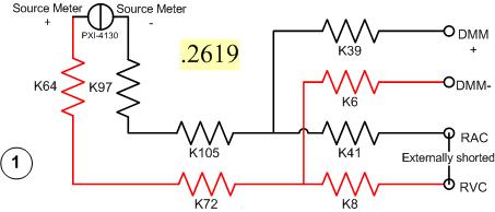
I have a problem with a PXI-2530 switch card work in matrix mode 4 X 32. I need to determine the resistance of the pairs of specific relay within the matrix. I have a PXI-4130 and a PXI-4071 in the same chassis, so I take measures 4-wire in a configuration like this...
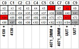
Resistance symbols represent relays in the switch. Here is a representation of matrix-style switch routes I use. (This should look more like the interface of soft face before switch)
The two diagrams represent so how I take my measure. I shorted outwardly columns C8 & C9 (shown in the first graph), I am sourcing 500 microamps of current and toggling the current source for a positive and a negative measure, I am able the voltage with the DMM. For the above measure I'm mesure.2619 ohms. This should be of course my resistance of the relay K8, K41, as well as Terminal block and wiring.
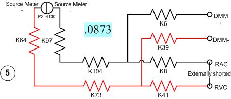
Here's another schema. This should measure the resistance of two same...
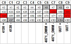
All I have changed is routing between the meter from the source. Here's the view from the matrix...
With this measure I'm mesure.0873 ohms. I can have the same resistance as the first example except getting a very different measure.
It gets even more interesting. If I had to take 4 pairs of wires, I use here, there are 16 possible configurations. I took each of these measures, and half of them gave me environ.25 ohms while the other half gave me environ.09 ohms. I tried this on a 2nd chassis and got the same result. My data are in the attached sheet. (My examples above are rows 1 & 5.)
Taking the measure of how we are, all these measures should be substantially the same. I have a current source constant, (I even tried a crimp in instead of the 4130 and got the same result.) and the meter is high impedance. If I had a pattern for the PXI-2530, I could do a little more analysis to know why I get various measures. Is there some diodes clamp on the lines or columns in the matrix? Something external must act solange this circuit. If I can find out what that is, I could determine my resistance to relay to a quantifiable level of uncertainty.
Any help would be greatly appreciated.
Greg
It seems that I can't remove. The correct message was placed here...
Once again, my apologies for the incorrect positioning of the post.
-
Use the PXI-2630 terminal block in a matrix configuration?
My apologies in advance for the length of this post!

I use the PXI system with PXI-2530 switch modules, related to a series of USE with PXI-2632 (1W matrix 8 X 16) connector blocks and a PXI-4071 DMM for each switch module. My request, uses the PXI system for measurement of current and voltage external to verify and/or benefit from restraints of reliability. A requirement of the application, therefore, is that there must be a ride from DC through each USE with change of the minimum impedance as the application between its "bypass" mode switches and its mode 'measure '.
I used this Setup with connector blocks of matrix in conjunction with one of our test systems, and I am satisfied with the results. I started working with the Test System, has no easy connection to catch HAD, I needed to build a kind of interface the PXI system and a resistive faced load HAD, it was not difficult to build in the wires that attach to the Terminal screw of the 2632. He did turn into a nest of a coded son rat I did my best to keep clean and tidy in different bundles, however. Fortunately for the cable fasteners!
My next task is to use this application with system B Test, which has an interface of pines buck header with which each signal that goes to or from the DUT can be obtained. No welding or pass the wires through the openings where the designers have no intention of son to be stuffed. I intend to build a break-out Board that allows simple connections between the modules PXI and the number of Test B system which we have or will have in our laboratory. In order to simplify the configuration/installation, I want to reduce the number of connections to terminal block screw. Preferably, I would like to completely remove the screw terminals and use lever-based connections where I can't have mating of the headers. The PXI-2632 terminal blocks unfortunately use Terminal screw.
In matrix mode 8 X 16, the closing of the PXI-2530 switch kcom1, 3, 5, 7, no matter what points in the array are connected. A link between the row of right and column C is done by closing the switch corresponding to k (16R-C). I checked using the Soft Front Panel.
I also have a number of connector PXI-2630 blocks. These are intended to be used with the switch module in one of its MUX modes and include 8 banks of connections of the header 2 X 9 pins. In the the 2530 documentation and 2630, I identified that switch k-x is associated to chX output pin, ch0-15 related to the pins 1-16 from Bank 0, C16 - 31-associated pins 1-16 of Bank 1, etc.. X = 16 B + P-1. PIN 18 of each bank is used for independent MUX topology comX. Pines multiplexes sixteen seem to correspond to the sixteen columns of the matrix, with eight common lines corresponding to eight lines.
Here's what I would do, but I would like to ping the forum to see if anyone tried something similar and wisdon to share the thought:
- Make custom cables which connect the pins 1-16 of all eight banks 2630's header with a single Ribbon connections 16 son carrying the signals emitted by the interconnected banks (poles!).
- The custom cable bundle will also include a wire connected to the pin18 of each of the eight banks (line connections!)
- 24 total wires in the harness will end in the header connections who will probably partner by the lines that I currently connect to each object to be measured.
- Make additional harnesses that interface with the Test System B header pins.
- Make a map of derivation using band Council or a similar material to provide header pins to connect the two above custom cables and allow the connection of other elements such as resistors using Terminal level.
I checked this concept using the Assembly of 176 pins four terminals, like a bunch of little pieces of wire and cable. Are there other issues that I have to configure, such as the elements of a terminal that establish physical components of the switching topologies? The bowels of the PXI-2632 provide more features than the interconnection of the sets of eight sixteen pins? The bowels of the PXI-2630 connect elements that do not allow my proposed scheme?
I appreciate the suggestions and all entries!
Thank you
Jeff Zola
Hi Jeff,
First a correction to my previous post: 2632 Terminal has no reed relay protection resistors as I said earlier. The resistance that you were referring to the 2632 and those that I confused, is there to connect the columns of the switch. Resistances have a resistance value zero and act as the electrical connections. The 2632 connects columns c0 to c16, c17 c1, c2 to c18 and so on. Switch cards 2531 and 2532 have the protection relay reed on board resistors.
As for resistance in the map that protect the reed relays, they are generally very low and do not significatly affect even small tensions that pass through the switch. The resistance won't affect all currents in the map. Any effect that the resistors have on tensions will be with the precision of the switch card specifications.
Thus, to address the other issue in your post, there is no resistance in the connectors because they are not necessary.
-
PXI-2530/2567/2593 Instrument map self-test
Hello
We will use the PXI-2530,-2567 module, &-2593 instrument cards in our chassis PXI-1044. We use LabVIEW software coding ATE platform. We would like to perform a self-test on the cards before the measures of the object to measure. Do you have any documentation that will support this task? The approach to check the functionality of card better by querying the records of the State of the map? In any case, I can't find any information online about this topic.
Thank you!
Dan
Hi dan_tuq,
That's all! simply provide a valid handle for each call of niSwitch Self-Test VI. Good luck!
Kind regards
-
How can I display an analog input for the PXI-5105 on LabVIEW?
Hi all
I am very very new to LabVIEW and I started to tinker with it. I use the version of LabVIEW 2010 SP1 on Windows 7 OS. I also have the chassis NI SMU-1073 with SMU-6361 and PXI-5105 modules and the chassis is connected to my PC via PCI. I became familiar with the devices and trying to see some analog signals to one of the channels on the PXI-5105 module in a graph in LabVIEW.
I would appreciate your help.
Hello Henokview!
I would like to read through these tutorials to understand the steps of programming of the NOR-SCOPE, NOR-DAQmx. After reading these links below, you will be able to understand how to connect the output of a readfunction to a chart or table.
DAQmx
http://www.NI.com/white-paper/5434/en
OR-SCOPE
http://www.NI.com/white-paper/3382/en
Best regards
Jonas
-
Difficulties in finding devices on the PXI-1033
When looking at the measurement and Automation devices explore my NI PXI-7853R and 128Mux (PXI-2532) seems to work very well. However, when you load a project, Labview FPGA the new project wizard displays the error:
No PXI controller have been found on the network. Ensure that your PXI controller is correctly configured in MAX and try again.
dependencies the option 'R series Intelligent DAQ PXI real-time '.
A similar promblem arises when you use NISwitch, simply, it does not find the PXI-2532 module.
With labview, I have been able, for example using an example, reassociate the device and managed to compile a race as part of an existing project.
However, to my knowledge, there is no way to do it with NISwitch.
I tried to solve the problem by restarting the computer several times. Also tried re-installing the drivers NI Switch as well, with no luck
Hi Jayem,
It seems that you have a few different things and possibly multiple systems. Can you please provide more details about your concerns and your setup (s)? Where the creation of project FPGA (http://zone.ni.com/devzone/cda/tut/p/id/6358) you receive the error?
-
How to set up the PFI lines as input to PXI-6713 module
Hello
I have 6713 PXI module in my chassis PXI-1044. I have configured the PXI-6713 module to geneate some analog signals to my Board of Directors.
Council inturn process this analog signal and answers in return the status signals through a registry to the Board of Directors. In my application, the status bits in the register state of the governing body are mapped on the PFI 0:3 bits of the PXI-6713 (pins 11,10, 42 and 43) module.
My query is how can I configuration lines PFI as 6713 PXI module entries to read these status bits?
May be less than the explanation could give you little more information w.r.to my request.
When I use NI USB - 6008 module to read the same bits, because this unit has 12 e / s digital, I was able able to read the status bits in the last 4 digital lines by setting up those digital lines as input.
In the PXI-6713 module, I have only 8 digital lines. These 8 digital lines I used to send digital signals to the Board of Directors. I find myself with no digital i/o. Therefore, I could not use these digital lines. I'm left with only one option to use. Joana re PFI lines. Also the bits of status in the axis of the room are mapped such that the bits can be read through the PFI lines.
I was wondering do we have any example code to use inorder to read these status bits to the Board of Directors using the PFI lines.
Please let me know if you need more information to help out me.
Thank you.
Hello
When using the PFI PIN as input, you can individually configure each PFI for edge detection or level and the selection of the polarity. This information of PFI are referenced in the manual of Series DAQ Analog Output on page 6-1 (http://www.ni.com/pdf/manuals/370735e.pdf). Unfortunately, the PXI-6713 PFI lines are able to time a signal input and output for functions, AO or counters/timers. The ability to create static DI of the PFI lines is not available for the PXI-6713. However, some cards have this capability. The latest National Instruments products with PFI lines have the option of setting as PFI lines:
- Static digital input
- Static digital output
- Input signal of sync for functions HAVE, AO, DI, or counters/timers
- Output signal of the calendar functions HAVE, AO, DI, or counters/timers
(http://digital.ni.com/public.nsf/allkb/14F20D79C649F8CD86256FBE005C2BC4)
When the static value such as DIO, PFI lines are assigned to a different port (for example. PFI0-7 is Port1). More details on this subject can be referenced at:
http://digital.NI.com/public.nsf/allkb/DA2D3CD0B8E8EE2A8625752F007596E1
http://digital.NI.com/public.nsf/allkb/862567530005F09E8625677800577C27
-
What are the data for the PXI-6552-invalid range
Hello
Let say, I put the voltage custom for the PXI-6552 module
2.4V - high level
0.6V - low level
Then, on canal0, I provide a signal of
sample
3V 0
1 3V
2 VOL. 2
3-0V
Thus, the sample 0.1 is high. Example 3 is Low.How sample 2? Please notify. Thanks in advance.
Hi Engwei,
Programmed tensions are the levels that you would have to exceed or down before a change of digital status is saved. This means that in your example, coming from a high level of 3V goes to 2V, the Analyzer signals would still record a strong logic. The deadband is actually a way to filter digital noise, common to the majority of the architecture of digital input.
Best regards
The Ilana Joshua
Applications Engineer OR -
Dimensions of 160 cable pins for the NI PXI-2530 b
Hello
My mechanical design team wants to know the measures of the 160 cable pins for the NI PXI-2530 b. It will take a while before we get the cable we ordered. I couldn't find a data sheet with details of the measure; are they? Alternatively, y Figure 1 in the Installation Instructions to scale? : http://www.ni.com/pdf/manuals/375656b.pdf
Thank you!
Hi JKSH,
I'm sure you've probably noticed, that the specific documentation is not accessible to the public. Please create a demand for service by clicking here and using the tools on the right side of the screen. Once you have created a service request, we continue to assess your situation and we hope to get you the documentation you need. Although parts of it may be, I'm not quite sure that figure in the manual that you have accessed is perfectly to scale. So, contact National Instruments more directly can be a better option for you.
-
Hello
We use the DMM and SMU-6363 map to test a hardware device. We will also use a PXI-2530 b switching matrix. We will use the digital multimeter to perform the measurements of voltage, DC and AC, measurements of impedance (2-wire and 4-wire), frequency and waveform acquisition. Can the PXI-4071 left be 4 wire connected (black jacks taken connected and red connected) mode and still be used to perform all other measures (including 2 impedance of the cable). This would simplify the switch connections.
Current measures use the son + and LO, but the HI and S-can remain connected. The problem you are having is if you have an active device the digital multimeter and take you a 4-wire resistance and the measurement of voltage with all 4 wires connected and then change to a current... When you do this, short-circuit you the terminals of the DUT, on that you just take the measurement of the resistance. If the terminal HAD, say, a power supply 10V, then you have just shorted out. Of course, this isn't a problem if your Instrument is a passive device, or if you change just the unused two lead whenever there is an active device of low impedance.
If you want to make voltage, current and 4-wire resistance, you need all 4 wires. If you want to do the voltage and current, you will need 3 wires, but you could connect the s + Hi and then just do the two wires. I vote running every 4 son to your DUT for maximum flexibility.
2-wire resistance is a must if you are measuring resistance above 10 MOhm. Alternatively, you can use 4-wire for all measures.
-
PXI-2530 query if row and column are connected
I use niSwitch Connect Channels.vi and niSwitch Channels.vi of disconnection to control a PXI-2530, the connections are made via an NI TB-2631 defined as a 4 x 32 1-wire matrix.
Is there a way to check if a column and a specific line to be connected or not connected?
If they are connected, trying to connect them again causes an error. Similarly, if they are not, trying to interrupt causes an error.
The strings that I use are to take the place of a switch on a Board, I develop the test. This switch allows the adjustment of frequency so I have sup - screw to use at appropriate times to switch to the frequency and to move to the frequency B. The problem is, if I already am frequency and attempt to set often has once again to another part of the test, I get an error.
Test structure is based on State Standard computer in the examples of LabVIEW. Because the test sequence can 'jump around' depending on the outcome of a test (I may need to redo a test if it fails), it is difficult to keep track of what state the frequency is set to.
LabVIEW 8.5, Windows XP SP3.
Kind regards.
Hi sebster,
niSwitch can connect Channels.vi checks whether a column and a specific line to be connected or not connected. The ability to access path output indicates if a path is valid. I list below the possible values of the output of path capacity:
(1) available path the path is possible and available.
Path Exists (2) the path is possible, but it already exists.
Path not supported (3) path is not possible in the module switching specified and topology.
Resources to use (4) the path is possible, but the track components are in use by a different existing path. You must destroy the other lane before creating this one.
Source of conflict (5) the path is possible, but the channels will connect two sources.
Channel is not available (6) channel 1 and channel 2 are configuration strings aren't available for external connections.I hope this helps!
Chad Erickson
Switch Product Support Engineer
NOR - USA
Maybe you are looking for
-
We bought a HP Officejet Pro 8600 a year ago and set up two laptops and a desktop computer to print to it. For the past 6 months my laptop was unable to print to it. We have tried re adding to my laptop but it says that the printer is not found. Help
-
full screen with voice message message
The message says to call the 1-855-244-7750 immediately to check any activity suspicious. They want $99 to check - I was browsing, nothing downloaded - I want to be happy something Apple catches the clerk on the phone said that they are not Apple, s
-
NetWare migration of Microsoft
Needing a way to migrate data from a NetWare 6 x box to Windows Server 2008R2. I've seen references to using Robocopy. It would be the preferred method? What options and "traps" should be aware of? Any recommendations? Thank you
-
Can I have 2 versions of Internet Explorer downloaded on my computer?
I upgraded to IE 9, but need version 8 for a website that I use for school. Is it possible to have two different versions, downloaded on Windows Vista? Like having Mozilla and Internet Explorer, or IE 9 replaced so will I download IE 8?
-
VPN between Cisco and Check Point problem
Guys, I have problems to establish a vpn site-to-site between a Cisco 3660 e router tunnel a firewall checkpoint NG AI R55. In the SiteA is an environment with a Cisco 3660 router using the following configurations: crypto ISAKMP policy 1 md5 hash pr