Input setting on the PXI-4071
The specifications for the PXI-4071 DMM indicate the input resistance can be chosen as 10 MOhm, 10 GOhm of the 100 mV 1 V and 10 V ranges. I see where it can be entered on the soft dashboard, but I could not find how to set up the input resistance when you use the DMM in a VI. Suggestions?
Thank you!
The f
You must use a property node.

Tags: NI Products
Similar Questions
-
Hello
We use the DMM and SMU-6363 map to test a hardware device. We will also use a PXI-2530 b switching matrix. We will use the digital multimeter to perform the measurements of voltage, DC and AC, measurements of impedance (2-wire and 4-wire), frequency and waveform acquisition. Can the PXI-4071 left be 4 wire connected (black jacks taken connected and red connected) mode and still be used to perform all other measures (including 2 impedance of the cable). This would simplify the switch connections.
Current measures use the son + and LO, but the HI and S-can remain connected. The problem you are having is if you have an active device the digital multimeter and take you a 4-wire resistance and the measurement of voltage with all 4 wires connected and then change to a current... When you do this, short-circuit you the terminals of the DUT, on that you just take the measurement of the resistance. If the terminal HAD, say, a power supply 10V, then you have just shorted out. Of course, this isn't a problem if your Instrument is a passive device, or if you change just the unused two lead whenever there is an active device of low impedance.
If you want to make voltage, current and 4-wire resistance, you need all 4 wires. If you want to do the voltage and current, you will need 3 wires, but you could connect the s + Hi and then just do the two wires. I vote running every 4 son to your DUT for maximum flexibility.
2-wire resistance is a must if you are measuring resistance above 10 MOhm. Alternatively, you can use 4-wire for all measures.
-
Error-1074118625 with the PXI-4071 and PXI-2527
When you use the LabVIEW and PXI-4071 PXI-2527 IVI drivers, I get a 1074118625 error in TestStand. The sequence that initializes the MUX, init DMM, connects the MUX, expected debounce, and then to the DMM reading, I get this error.
Error: niDMM .viExplanation of waveform (waveform data) reading is not found for the requested status code.
Check that the required status code is correct.
[Error code: error code defined by the user of 1074118625.]
This sequence of events is used successfully several times elsewhere in the TestStand. This error does not appear in any section of the knowledge base, or any help. Any explanation would be greatly appreciated.
I found this with google that seems like it could apply:
http://digital.NI.com/public.nsf/allkb/A593DEBFD86A69C68625727900748EEC
-
I tried to change the name of the PXI-4071 "DMM" that worked, but when I try to launch the "self-test" or open the app it Panel always fails. This is also true if I pass the new name of the ivi driver. Return to the name "PXI-4071" makes everything works again. Note I managed to change the name of our PXI-2530 b 'SWITCH' and the name of our SMU-6363 to "MIO" and I could pass these names to their IVI drivers and they would work.
I messed with alias VISA, IVI logical names, but nothing works unless it is called "PXI-4071.
-
Problem of reliability data acquisition PXI-4071
Hello
I'm having a problem of reliability using my 4071 Pxi digitizer mode.
I have a number of tests that use the SMU-6363 (usually configured for DC) analog output to provide a stimulus for our own device, which has a number of a/d converters. We use the PXI system for calibration and testing.
1. I select a voltage ranging from tensions.
2. program the PXI-6363 to drive this tension
3 TIME about 10ms to settle. Note there no discrete capacitors or resistors in the circuit. Everything is parasitic and would generally be under the nF mark and less than 10 ohms
3. configure and Initiate() acquisition of data with the PXI-4071. In general, I use a sample rate of 1000 s/s and get about 30 samples (worth 30 ms). Activation is immediate and I used the default a queue time, 0, set the time and it doesn't seem to make a difference.
4. measure the voltage with the CDA. For debugging purposes I have sometimes made twice once before calling Initiate() and once after. The after is normal. The time required to measure the ADC is shorter than the acquisition time, but regardless of stimulation by the SMU-6363 is constant
5. extract the waveform.
6. the average waveform and compare the value of ADC measured by applying tolerances etc.
Here's the problem: it works well most of the time. But only 0.1% of the time (1 on an acquisition of 1000), I get 8-12 samples that are close to 0. It sounds like a problem of time settling (on the surface), but no matter the amount of wait time data, I always get this behavior. Not only that, but the tension before the call to Initiate() in height CDA, it always confirms that the motor voltage is already set to the programmed value. Nevertheless the acquisition presents near data 0.
So far our independent ADC always reports the expected before and during acquisition (100%) voltage. It's like the DMM input is disconnected during the acquisition during a period of time, because we have confirmed that the voltage is already present prior to the acquisition (component can). I have no errors the insider or FetchWaveForm calls. I still have all my samples. And 99.9% of the time that everything works as expected.
The DMM and ADC are connected to the same point and both are referenced to ground, and as I said before only the parasitic capacitance and resistance (cable). We use a matrix of switching (PXI-2530 (b) to make these connections. We almost always use 51/2 digits and 10V range for data acquisition.
Hello
I thought about it and was going to repost but am distracted.
The device with the ADC also has a mux and switches the mux to an internal node. It only switches when measuring and is open at other times. There is a race condition where the acquisition starts too early and maintains the acquisition after that the switch is open. Unfortunately I don't have the option to trigger.
I forgot the internal mux that I had designed the test years ago and I did some updates to improve the stability of the test. That's why we start the ADC measurement when acquiring.
I just added a routine to reject samples below a threshold
-
Hello people,
I recently updated my CalExec 3.4 3.4.1. Desktop XP OS.
I can't calibrate the PXI-4071, I have not had any problems in the past.
MAX has no problem seein' and it makes even the inside however calibration option, with CalExec I get as much as
update from the slot, after that this error... Error-1073807297.
I have attached a hood perforated of all error... can you help out me.
I have a Chassis1042 w / counterpart 8330 PXI AND PCI and PXI-GPIB.
Thanks in advance.
Hey JSOTO,
You connect to any equipment calibration using VISA? If so, you can check that all these devices are rising and successfully through VISA? If one of the VISA alias is incorrect, then could you appears as this error.
My recommendation is to start Trace of e/s OR (formerly known as "NOR-SPY) (start" all programs"National Instruments" NI Trace of IO). Then try to calibrate the unit. I/o path will record all calls VISA and could lead us to the root cause. Once you have saved the data, you can export it and send it to us. If you are not comfortable posting all data on this forum, then you can post only the steps leading to the error or we can contact you by e-mail and continue troubleshooting it.
Tell us what you find.
-
Control PCLK when using the PXI-6534 in e/s mode
I use ports 0 & 1 on the PXI-6534 in e/s model mode and also use output control in the mode of e/s to unstrobed for simple. Users manual says in the mode of e/s model the PCLK control is not used, but the mode of e/s model seems to put down (or maybe he defines as an entry). This a problem for me because I expect to PCLK to stay a high return which I set earlier. Does anyone know how to set up the PXI-6534 in e/s model mode so that this does not affect PCLK... He's going to stay high?
Thank you.
Jim
Hi Jim,.
According to page 2 and 3 of the PXI-6534 user manual, if you configure a group to perform i/o, associated for this group synchronization control lines are not available in the form of additional data lines. The knowledge base, here, explains this limitation for the PXI-6534. In summary, port 4 is reserved once you are in e/s handshaking mode or a model and cannot be used as data lines additional unstrobed.
-
How to set up the PFI lines as input to PXI-6713 module
Hello
I have 6713 PXI module in my chassis PXI-1044. I have configured the PXI-6713 module to geneate some analog signals to my Board of Directors.
Council inturn process this analog signal and answers in return the status signals through a registry to the Board of Directors. In my application, the status bits in the register state of the governing body are mapped on the PFI 0:3 bits of the PXI-6713 (pins 11,10, 42 and 43) module.
My query is how can I configuration lines PFI as 6713 PXI module entries to read these status bits?
May be less than the explanation could give you little more information w.r.to my request.
When I use NI USB - 6008 module to read the same bits, because this unit has 12 e / s digital, I was able able to read the status bits in the last 4 digital lines by setting up those digital lines as input.
In the PXI-6713 module, I have only 8 digital lines. These 8 digital lines I used to send digital signals to the Board of Directors. I find myself with no digital i/o. Therefore, I could not use these digital lines. I'm left with only one option to use. Joana re PFI lines. Also the bits of status in the axis of the room are mapped such that the bits can be read through the PFI lines.
I was wondering do we have any example code to use inorder to read these status bits to the Board of Directors using the PFI lines.
Please let me know if you need more information to help out me.
Thank you.
Hello
When using the PFI PIN as input, you can individually configure each PFI for edge detection or level and the selection of the polarity. This information of PFI are referenced in the manual of Series DAQ Analog Output on page 6-1 (http://www.ni.com/pdf/manuals/370735e.pdf). Unfortunately, the PXI-6713 PFI lines are able to time a signal input and output for functions, AO or counters/timers. The ability to create static DI of the PFI lines is not available for the PXI-6713. However, some cards have this capability. The latest National Instruments products with PFI lines have the option of setting as PFI lines:
- Static digital input
- Static digital output
- Input signal of sync for functions HAVE, AO, DI, or counters/timers
- Output signal of the calendar functions HAVE, AO, DI, or counters/timers
(http://digital.ni.com/public.nsf/allkb/14F20D79C649F8CD86256FBE005C2BC4)
When the static value such as DIO, PFI lines are assigned to a different port (for example. PFI0-7 is Port1). More details on this subject can be referenced at:
http://digital.NI.com/public.nsf/allkb/DA2D3CD0B8E8EE2A8625752F007596E1
http://digital.NI.com/public.nsf/allkb/862567530005F09E8625677800577C27
-
Would it not correct to say that the PCI-6110 can be set to 'redeclenchables' but the PXI-6115 module cannot use this property? If Yes, where is it documented the series cards can do trigger? For example, is it possible to configure the trigger on the PXI-6124?
Hi Joel_Neptune,
The PCI-6110 and other materials as the PXI-6115 S series and SMU-6124 do not natively support NOR-DAQmx analog input alarm. However, you can use one of the generalist counters/timers of the Council to generate a reenclenchees pulse train, then use this as the sample clock pulse train. This transportation example shows how:
LabVIEW\examples\DAQmx\Synchronization\Multi-Function.llb\Multi-Function-Ctr Retrigg Pulse Train generation for the Clock.vi sample
In addition, the new material of the simultaneous sampling X series are supported trigger analog input without using a separate task of counters/timers.
Brad
-
original title: windows live suit
When I try to open e-mail files a small box opens with the setting or the input string was not good format
Windows Live Solution Center
http://windowslivehelp.com/ -
How can I display an analog input for the PXI-5105 on LabVIEW?
Hi all
I am very very new to LabVIEW and I started to tinker with it. I use the version of LabVIEW 2010 SP1 on Windows 7 OS. I also have the chassis NI SMU-1073 with SMU-6361 and PXI-5105 modules and the chassis is connected to my PC via PCI. I became familiar with the devices and trying to see some analog signals to one of the channels on the PXI-5105 module in a graph in LabVIEW.
I would appreciate your help.
Hello Henokview!
I would like to read through these tutorials to understand the steps of programming of the NOR-SCOPE, NOR-DAQmx. After reading these links below, you will be able to understand how to connect the output of a readfunction to a chart or table.
DAQmx
http://www.NI.com/white-paper/5434/en
OR-SCOPE
http://www.NI.com/white-paper/3382/en
Best regards
Jonas
-
Variation of thermal EMF of the PXI-2530 modules
This message/question is a companion of my the most recent message in another thread.
In addition to watching some resistance higher than expected that affected current measurements using modules PXI-2530 multiplexer 4W topology, I saw systematic variation in track-to-track blood pressure measurements. Tensions would increase gradually through the 16 channels in a configuration by measuring the voltage at the terminals a resistor 1.5 kOhm with 0.5 au crossing (75 uV). I've identified that the thermal EMF of the reed in the PXI2530 module switches is on the same order of magnitude of these measures and set out to quantify the differences EMF thermal track-to-track between my three modules.
Test method: I have a TB-50 which is configured to mux the signals of tension for a DMM. I connected each of the four DB-50 one cable of 176 pins to this block and collected with a PXI-4071 pressure readings set to 7.5 digits precision in the range of 100 mV and > 10 GOhm impedance. For most channels, it took several minutes for the voltage stabilize - or at least appear that it was to stabilize.
I enclose three graphs. Note that the vertical scale is the same on each.
Data that triggered this survey was collected with MUX1, via connector P2 to voltage. The magnitude was not quite the same-probably related to the phenomenon of stabilization time, but obviously the worst group of channels three multiplexer modules.
The three modules were all bought at the same time (about 2 years ago), but had only limited its use in the first year or more. The three now have various 'mileage' based on my use. But MUX1 clearly behaves differently two other modules. The
I changed my test conditions to spend 0.5 au via a higher resistance to thermal EMF less important. The PXI-2530 sheets indicate that thermal EMF must be less than 50 uV. In most of my measurements, it is. But not for MUX1!
Any thoughts?
Thank you
Jeff
Hi Jeff,
You can check that all the three modules are PXI-2530, not PXI-2530 b (while, as the PXI-2530 b parts slightly higher thermal emf)?
Specification of emf thermal 50uV of the PXI-2530 is a typical value, is not a guarantee of spec. See a few channels higher than the spec is not a cause for alarm, but it shows that we must take account of this in our measurement error. Note that the industry standard for the technical measure thermal emf is to close the relay, wait a few minutes and then take a measure of tension. For example, if you scan through a switch faster than a relay per minute or so, the thermal emf will be less predictable and stable. A single module performs worse at these low voltages is not indicative that this module is a failure, etc. the module is fine. Unfortunately, the reed relays have more emf thermal relay of the armature, mainly because of the many layers of metal in a Reed compared to a frame (each metal junction is a source of emf if these metals are not the same).
Thermal EMF is proportional to the temperature, it may be interesting to note the position of the chassis of the less powerful module. Placing hottest modules (scanners, Ara, RF, etc.) will reduce the thermal emf.
-
Use the PXI-2630 terminal block in a matrix configuration?
My apologies in advance for the length of this post!

I use the PXI system with PXI-2530 switch modules, related to a series of USE with PXI-2632 (1W matrix 8 X 16) connector blocks and a PXI-4071 DMM for each switch module. My request, uses the PXI system for measurement of current and voltage external to verify and/or benefit from restraints of reliability. A requirement of the application, therefore, is that there must be a ride from DC through each USE with change of the minimum impedance as the application between its "bypass" mode switches and its mode 'measure '.
I used this Setup with connector blocks of matrix in conjunction with one of our test systems, and I am satisfied with the results. I started working with the Test System, has no easy connection to catch HAD, I needed to build a kind of interface the PXI system and a resistive faced load HAD, it was not difficult to build in the wires that attach to the Terminal screw of the 2632. He did turn into a nest of a coded son rat I did my best to keep clean and tidy in different bundles, however. Fortunately for the cable fasteners!
My next task is to use this application with system B Test, which has an interface of pines buck header with which each signal that goes to or from the DUT can be obtained. No welding or pass the wires through the openings where the designers have no intention of son to be stuffed. I intend to build a break-out Board that allows simple connections between the modules PXI and the number of Test B system which we have or will have in our laboratory. In order to simplify the configuration/installation, I want to reduce the number of connections to terminal block screw. Preferably, I would like to completely remove the screw terminals and use lever-based connections where I can't have mating of the headers. The PXI-2632 terminal blocks unfortunately use Terminal screw.
In matrix mode 8 X 16, the closing of the PXI-2530 switch kcom1, 3, 5, 7, no matter what points in the array are connected. A link between the row of right and column C is done by closing the switch corresponding to k (16R-C). I checked using the Soft Front Panel.
I also have a number of connector PXI-2630 blocks. These are intended to be used with the switch module in one of its MUX modes and include 8 banks of connections of the header 2 X 9 pins. In the the 2530 documentation and 2630, I identified that switch k-x is associated to chX output pin, ch0-15 related to the pins 1-16 from Bank 0, C16 - 31-associated pins 1-16 of Bank 1, etc.. X = 16 B + P-1. PIN 18 of each bank is used for independent MUX topology comX. Pines multiplexes sixteen seem to correspond to the sixteen columns of the matrix, with eight common lines corresponding to eight lines.
Here's what I would do, but I would like to ping the forum to see if anyone tried something similar and wisdon to share the thought:
- Make custom cables which connect the pins 1-16 of all eight banks 2630's header with a single Ribbon connections 16 son carrying the signals emitted by the interconnected banks (poles!).
- The custom cable bundle will also include a wire connected to the pin18 of each of the eight banks (line connections!)
- 24 total wires in the harness will end in the header connections who will probably partner by the lines that I currently connect to each object to be measured.
- Make additional harnesses that interface with the Test System B header pins.
- Make a map of derivation using band Council or a similar material to provide header pins to connect the two above custom cables and allow the connection of other elements such as resistors using Terminal level.
I checked this concept using the Assembly of 176 pins four terminals, like a bunch of little pieces of wire and cable. Are there other issues that I have to configure, such as the elements of a terminal that establish physical components of the switching topologies? The bowels of the PXI-2632 provide more features than the interconnection of the sets of eight sixteen pins? The bowels of the PXI-2630 connect elements that do not allow my proposed scheme?
I appreciate the suggestions and all entries!
Thank you
Jeff Zola
Hi Jeff,
First a correction to my previous post: 2632 Terminal has no reed relay protection resistors as I said earlier. The resistance that you were referring to the 2632 and those that I confused, is there to connect the columns of the switch. Resistances have a resistance value zero and act as the electrical connections. The 2632 connects columns c0 to c16, c17 c1, c2 to c18 and so on. Switch cards 2531 and 2532 have the protection relay reed on board resistors.
As for resistance in the map that protect the reed relays, they are generally very low and do not significatly affect even small tensions that pass through the switch. The resistance won't affect all currents in the map. Any effect that the resistors have on tensions will be with the precision of the switch card specifications.
Thus, to address the other issue in your post, there is no resistance in the connectors because they are not necessary.
-
PXI-4071 sampling too slow when using a hardware trigger
We use 3 PXI - 4071 s in parallel to measure with accuracy of high voltages. The program is written using LabVIEW 8.5.1.
An additional test condition has been added which requires the use of a quadrature decoder and the synchronous DMM.
We thought it would be simple, using backplane trigger 0.
However, something odd happens.
With a low-cut VI that uses a single DMM, we get 100 microseconds time to sample running with internal triggers. However, if the overall relaxation or trigger of the sample is set to TTL0, the sample time becomes so 5.1 milliseconds. It seems very strange that even just definition of overall relaxation, expected to affect only the time of the first sample, not the time between samples, has that effect. The plug for the DMM also said, that the maximum trigger rate is of 6 kHz.
We have confirmed this reported sample time is independent of the speed of the clock actually connected to TTL0. If the clock is faster, it gets the reported sample time. If it's slower, the samples occur on the edges of the clock.
Does anyone know if there is a parameter that has a default that changes based on the source of command and can be changed to work around this problem, you?
I found the solution to this.
Over time the value-1, the DMM uses a short value (less than 100 US) to set hour when, in modes triggered internally. However, he used much longer (about 5 ms) when the value - 1 and with the help of a hardware trigger.
If the running-in is set to 1e-5, i.e. 10 microseconds, "the estimate" returned for conversion period goes from 5.1 ms 100, we and conversions actually occur at a rate set when clocked with trig 0-5 kHz
-
Is it possible to route signals of relaxation between two chassis PXI-1002 with the PXI-8335?
Hello
as the subject says, I am interested in the delivery of a signal to trigger between two chassis PXI-1002. At present, these two chassis are connected by a MXI - 3 system using maps PXI-8335. The software is Labview 2010 sp1 and 380 NIScope drivers.
We want to keep (a PXI-5122 by chassis) scanners supply separated due to the requirements of our measure! The chassis are connected via cable to fiber optic. This explains why I can not just use the shutter release in Star, or connect via 'Trigger' or 'clk' cards (the inputs / outputs to the front of the cards).
I found a few examples, but they seem to all be designed for use with a chassis only, I'll call later to the examples that inspired me to this point. Each guide explaining the synchronization of several chassis systems seems to use another material or VI is not accesible to me. This makes me wonder if my hardware has the capacibilities I need.
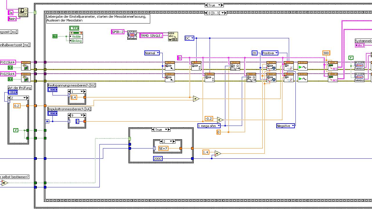
The first picture shows approximately where I started from (sorry I can't post VI, confidential...):
Only the middle part is interesting. Two sessions are initialized and manipulated parallel, trigger too. This has led to delays in the signals and should now be fixed. This apart from the VI works fine.
Goal is to trigger only on one channel but both devices! If possible, the device will trigger must be chooseable.
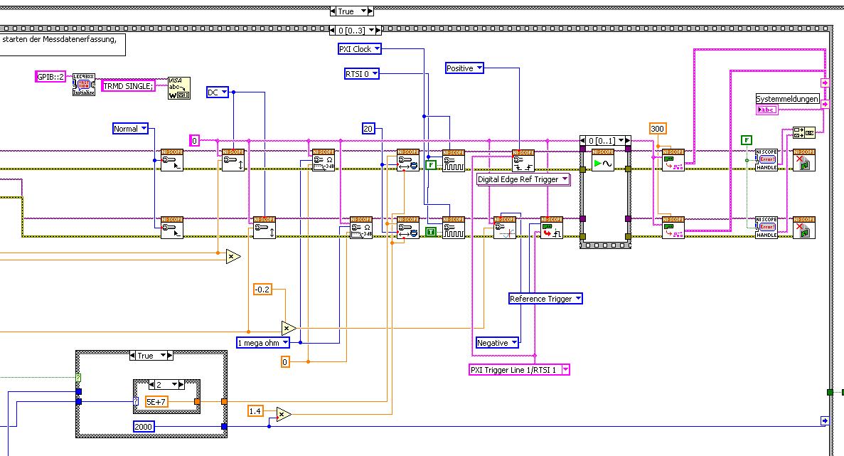
I started to rebuild the VI using the "EX Synchronization.vi 5xxx niScope' seeming spontaneity. The result is shown in the following image:
I tried different RTSI lines, but had no positive results. only the main channel has triggered.
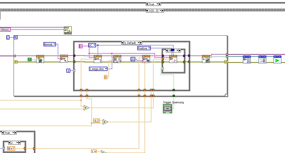
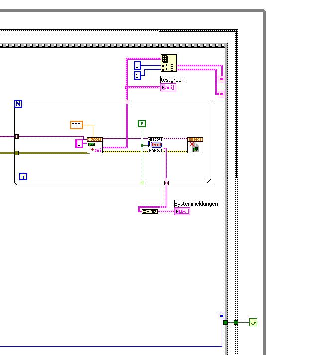
After this first approach, I looked in the "niScope EX .vi multi-Device configured Acquisition (TClk)" and other examples of TClk which seem to work for similar problems. The VI of reconstruction can be seen in the following images:
(Sorry, I had to use two photos..)
In this case, I didn't have no choice for trigger lines, it would automatically set the VI TClk. I tried to trigger on both devices, though. This second approach seemed promising to me, but it was an error:
"niTClk Synchronize.vi:1".
Index (starting at zero) of the session: 1
The error reported by the pilot of the instrument:
No registered trigger could be found between the
devices on the route.If you have a PXI chassis, the chassis correctly identify in
MAX and make sure that it has been configured correctly. If you use PCI
devices, make sure they are connected with a RTSI cable and that the cable RTSI
is saved to the MAX. Otherwise, make sure that there is an available trigger line
the trigger bus shared between devices.Source device: PXI1Slot4
Target unit: PXI2Slot4
Status code:-89125niTClk Synchronize.vi:1
Index (starting at zero) of the session: 1
The error reported by the pilot of the instrument:
No registered trigger could be found between the
devices on the route.If you have a PXI chassis, the chassis correctly identify in
MAX and make sure that it has been configured correctly. If you use PCI
devices, make sure they are connected with a RTSI cable and that the cable RTSI
is saved to the MAX. Otherwise, make sure that there is an available trigger line
the trigger bus shared between devices.Source device: PXI1Slot4
Target unit: PXI2Slot4
"Status code:-89125"
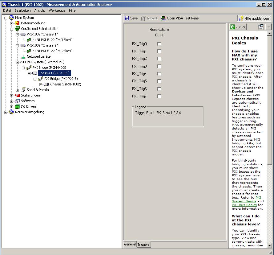
This error came back even after I've identified this drug as possible to the MAX, as shown in the screenshot:
In some of the textbooks, they showed how to get the MAX trigger lines, but as you can see, there is only booking options in my MAX. Whatever I do, I can't find options to define how to get my trigger signals...
In principle, it is possible to trigger instruments in different chassis, which is indicated in this Guide and others... the question that remains is can it be done with my set of components?
I understand that the use of multichassis compromised the integrity of the lines very adjusted as trigger in Star etc., so the configuration should be taken into account in some way, that my approach does not, I knew... But there must be a way to do this? And to start: to get just any signal from one device to the other trigger!
For any advice on this issue, I would be very thanfull!
Concerning
Max1744
Hi Max,.
Thanks for the detailed post and explanations of your application and requirements. You're right using TClk, because this is the optimal method to synchronize the 5122 digitizers. The original VI you worked with is unique for some of the legacy scanners and does not directly work with scanners based on the most recent CMS (for example the 5122). The good news is that you can synchronize these cards to separate chassis, but it will use the calendar 66xx and synchronization (T & S) cards in the chassis of the master and the slave, as indicated in the guide that you have accessed. These are needed because a common reference clock must be shared between them as well as a couple of tripping. MXI itself can not handle export triggers and clocks, so there is no way to do this without physically wiring between the chassis with cards T & S. Unfortunately, regardless of what specific method, you use for synchronization, it will take a material extra beyond what you currently have.
As one of your needs looks like it is necessary to retain wiring between the chassis directly, you may need to consider to synchronize using 1588 or GPS protocols. 1588 Protocol is a system for synchronization on the network while GPS course use antennas and locks for a common wireless signal. Although these synchronization methods may allow you to keep your chassis isolated, they will also require some manual configuration because you would be able to use the TClk synchronization and so the level of synchronization you can get between the cards may not be as good that can physically wire signals between the chassis using T & S cards.
Hope this helps,
Maybe you are looking for
-
iMac became very slow and unresponsive
Hello I have an iMac which, in the last two days, suddenly became unusably slow. Almost every click brings up the spinning beachball even just after a reboot. iTunes cannot play a melody without pausing every minute or two. Same Safari is really slow
-
Trial period the Bluetooth manager remains in 17 days
The Bluetooth Manager know I left 17 days.Do I have a key with my VISTA update?We can get a?There is a German version and I don't know what happens if the period ends ets.Is there an alternative?
-
I have a program that has changed my Aero theme, so I changed it to my saved theme, and now when I fly over programs I pinned to my taskbar, it only shows me the name of the program that is running and not some more. I looked in my settings, but I ca
-
Time synchronization between the module of SFR (ASA5512) and the power of fire management center
Hello. I deploy my network Cisco Management Center (for VMWare, v. 6.0.0) FirePOWER and tie SFR-module of Cisco ASA 5512. After you apply time in CMF settings, I have a synchronization errors for my module SFR ("TimeFor 172.16.x.x synchronization sta
-
1841 = > unable to connect via SSH
I am able to connect to the router via a tunnel of crypto isakmp using telnet. However, I'm unable to configure SSH on this thing. Can someone help me please in what I may be missing. I'm now at an impasse. I posted the router info and entered simila