Connection to the input NI9403
Hello
I use a NI 9403 DIO module in my project. I want to connect to one of the DIO pins as output, at the end of the collector of the optical switch PC845. The output level would be defined of salvation or + 5v. Then take the transmitter of the optical switch up to an another rod of DIO, as input. Can I do this without using the current limiting resistors? Current limit is the NI 9403 module it is out? If I use a value, what value can be used with the drop of resistance that is located on the entrance? What is the value of the resistance to pull-down on the inputs? I don't see a specification for it in the manual. Basically, I want to use the optical switch to allow a DIO output to the reader that the condition of the OID of entry based on the switch is enabled or not. The PC845 has a Vce = 1v. Or I'll have to set up the circuit in the traditional open collector configuration?
Your help is greatly appreciated.
Todd Moore
Hi Todd,
You should be able to connect the collector directly to a digital output and line from the transmitter directly to a line of input. When the optical switch is active, it is similar to the pines and DI being short-circuited together. This will not cause the device to a source or sink more current than it can handle.
You can find information on over-current and short-circuits on page 9 of the Manual: http://www.ni.com/pdf/manuals/374069e.pdf#page=9
Kind regards
Tags: NI Hardware
Similar Questions
-
Problem - VGA output VGA or HDMI port does not work when the connection to the input of your TV
Problem of VGA output - using an acer aspire 5520-5912 trying to connect it to the TV input - connect S-Video works well - port however VGA or HDMI does not work - 1 when I plug the VGA cable that goes to an entry of RD Gr Bl on TV, my screen goes black - as soon as I unplug the cable and press FN + F5 I get the screen back - if I restart the computer in order to have the computer to identify the external screen it will just a black screen when the priming. Troubleshooting using no external monitor is identified unless I use the S-video connection. The Hdmi connection gives me the same result that the VGA - convenience store attempt will identify the computer screen. OPSYS Vista. Thank you
Hi cdk14031
You have set display up-to-date drivers installed?Step 1 :
To resolve the problem, you can check if the uninstall and reinstall so help display drivers.
Also check if you have any exclamation point or cross the marks on the sides of display devices listed in Device Manager.a. click Startand then click Control Panel.
b. click system and Maintenance, click Systemand then click on Device Manager.
Note If Control Panel is in Classic view, double-click System, and then click Device Manager.
If you are prompted for an administrator password or a confirmation, type the password, or click allow.c. in the Manager device, expand display driver, display devices, right-click and then click on Properties and on the driver tab, click Uninstall.
d. When you are prompted to confirm that you want to remove the device, click OK.
e. restart the computer.
After the computer restarts, the drivers will be installed automatically.
Step 2:If the problem persists I suggest you to check if you install the latest updated driver on the manufacturer's Web site to help you.
You can also check out the link below and check if you get an updated video driver. You can install updates in optional updatesvideo card driver.
http://Windows.Microsoft.com/en-us/Windows-Vista/update-a-driver-for-hardware-that-isn ' t-work correctly
You can also check the support link and check if these help - belowhttp://Windows.Microsoft.com/en-us/Windows-Vista/connect-your-computer-to-a-TV
I hope this helps.
-
Connection of the inputs and outputs of a VI
Hello
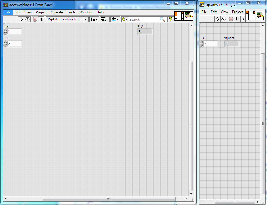
I'm relatively new to TestStand but I'm tying a VI with output entry. So I did a sample project and do the following:
First VI:
Takes two numbers and adds them, and returns the result in an indicator
Second VI:
Takes a number and square and the fate
They look like this
I can do that quite easily in Labview, I would just link out of the first VI at the entrance to the second VI. I can do this in TestStand?
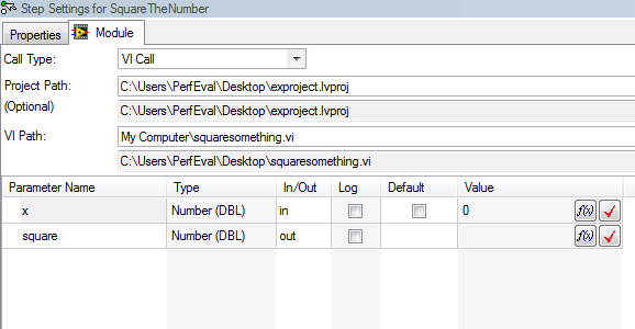
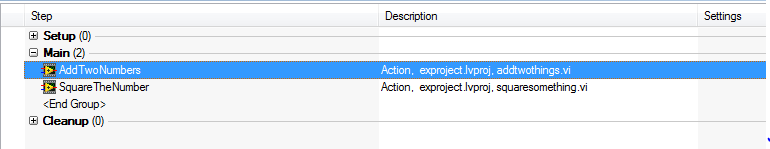
I only get that much until I got stuck, as shown in the image below:
What I have to hit f (x) then bind it somehow the first VI in my main installation? (which looks like this :)
Apologize in advance if it's really simple and miss me something obvious!
Any help is greatly appreciated.
See you soon!
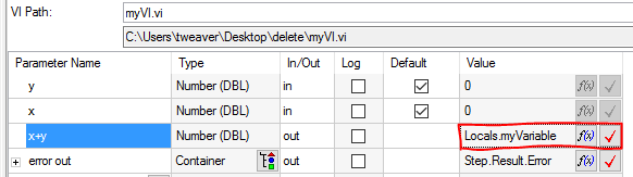
You can use a variable to pass data around TestStand:
- Right lick under local sections in the Variables pane
- Insert local' number' (give your variable name)
- Write the output of your VI to this variable (using the f (x) or typing on):
- Pass your variable in the next VI.
You will probably find the get started with TestStand useful guide, chapters 5 and 11 variables and cover VI.
I hope this helps!
Trent
-
Satellite L300 - 29 X - how to connect to the TV?
I have a Toshiba Satellite L300-29 X with a mini-VGA output and want to connect it to my TV, preferably by the DVI - I analog/digital double entry, but impossible to find a cable that will do it. Can someone point me in the right direction? I live in the United Kingdom and as such, have access to retailers based in the United Kingdom and do not want to pay the exorbitant costs to import from abroad.
If all else fails, I could connect through the input SCART on my TV, but once again, someone could point me in the right direction of a cable that could do that?
Cheers in advance for any help.
C
I also noticed just my TV has an entry of RS232 9 pin so if that's any help?
Hey,.
As I know there is no analog/DVI adapter, DVI only of-analog adapters available.
The connections you have on your TV?
Usually, you can use a RCA VGA adapter to connect your laptop to the TV as [THIS | http://images.ncix.com/forumimages/12BADAB5-13A6-D8D7-0372158257AC5AE9.jpg] a. -
Change of keyboard USB external Apple connected to the Macbook Pro
Dear ladies and gentlemen,
I need your help. I have a MacBook Pro running the last Sierra 17 "MacOS. I bought a 27 "Thunderbolt display and wanted to use a full external keyboard USB Apple (with the help of the digital keys). I have connected to the screen "USB port, closed down the internal screen MacBook... magic happened... keyboard poped office to the top of the screen external AND external full resolution was working properly..." Unfortunately only for 1-2 minutes, then the layout changed back irreversible in a layout resembling the layout if I would press "alt". Only way I could "resolve" to disconnect the keyboard USB plug and then plug again... but after 1-2 minutes did the same thing...
I tried to plug the USB plug into the MacBook Pro directly, but the same thing happened...
I am so unhappy that I can't use correctly the full length external Apple keyboard, large... Any hint/resolution?
Thank you for your help in advance,
Péter
System Preferences > keyboard > Input Sources > [√] see Input menu in the menu bar
... then the menu icon before, choose «Show Keyboard Viewer»
Now, look at the chart of the keyboard that appears on the screen. If the Alt/Option key is stuck, the key will be gray, as if it is held down. If you press it again, he himself is not?
-
Qosmio G30-116: how to connect to the Sky Digital box to watch TV?
I recently bought the Qosmio G30-116, with the understanding that I can connect my digital Sky to the laptop (somehow) and watch and record the sky on the laptop
* note: I do not use TNT or TV I'm on SKY DIGITAL *.
SINA the converter cable provided to connect the video in on the laptop (video is like a headfone Jack and converter converts to this female RCA/RCA)I connected on the laptop and then connect a RCA 3 SCART toward it then in the area of the sky, when you set up the TV section in Windows Media Center, I followed the instructions until it gets to the point where it scans a signal, (before that I wonder what kind of signal that I receive, I select digital but have tried all combinations in) but it does not find a signal.
Now I was told that Windows Media Center doesn't support analog input and the connection between the sky and the laptop is analog.
Is this correct or not? then, while typing this I learned by someone else that my laptop is not capable of receiveing SKY DIGITAl as it cannot decode or something. Is that also correct? If not, can what am I doing wrong, and someone help me to get it going? And I go about it the right way or I'm quite the wrong way if the laptop is capable of it?Hi Liam
AFAIK if you are using an external receiver (sat receiver or even sky digital box) the laptop can bring out just what external device send to the laptop. You can connect your external case to the laptop using composite to the port (transfer of video and audio signals). After that, you can start Qosmioplayer and analyze the available channels.
You will find a program, but the different channels, you must select the box itself. If a channel must be registered, use Qosmioplayer save option.
The same must be possible with WMCE. I'm not 100% sure but I also think that the connection between laptop and Skype is analog.
Sorry, but that's all I know about Qosmio. I tested it with Qosmio G20.
-
OfficeJet 6600 e-all-in-one: Wireless connectivity with the new router problem
We had the printer since 12 months, workin with no problems.
Just got a new modem/router (NETGEAR V7610) installed as part of the NBN implementation and I can't get the printer to connect to the new router. 5 and 2.4 G active networks. The two defined newtorks on security WPA2-PSK [AES].
The printer detects the wireless (2. 4 g) network, but can't coplete the connection. Tried the two direct input the network key and using WMA.
-The display panel shows "wireless invalid password (WPA) is entered.
-The results of network printer test page indicates a FAILURE on safety.
I was able to connect to multiple other devices (laptop, iphone, Kindle...) without any problem. Used the two direct entry of the key network and WMA.
Anything else I can try?
Find a new update of the firmware for the printer (May 9, 2016).
After you apply the update, the printer is able to connect to the new modem.
-
Satellite Pro L510 - unable to connect to the Internet
Hi, a newbie on this forum so here goes. I got the "fix Windows 7" virus on my laptop because my virus protection that flows. I downloaded AVG which solved some problems, but still not back to the original values. I reloaded Windows 7, but of course I lost all the software preloaded Toshiba & now cannot connect to the internet (laptop computer purchased through the catch of the day).
What I need to download software/drivers toshiba etc. to address this problem. Thanks for any input.
Hello
> now unable to connect to the internet
Can you write more than one sentence about your problem?Does anyone know how you connect to the Internet via modem, LAN or WLAN? More exactly, what happens if you want to connect, you an error message or probably t can find the router?
Sorry, but without this information there s no end of discussion
-
Question about connecting to the network with a Terminal window
Windows XP Pro, SP2, Fritz-card PCMCIA-
Hello
I am trying to create a connection from computer to computer by ISDN telephone line.
I didn't install any software of specific composition, I only use the parameter of MS WinXP.
Hardware works fine, I tested it successfully in composition in any other internet provider.Now I need to connect to a corporate network and they have a specific logon policy, where I need display Terminal window during the login procedure.
So I turn on dial in properties connection on page "Security properties" dialogue box "show Terminal window.Problem during dial-in: the window does not occur.
Second problem: if I go next time to this option, the input value is not saved.Any ideas?
Kind regards
PeterPlease don't be crazy about me, but I don't see what's in your specific assignment for the Toshiba forum.
You should speak with your company's network administrator and it should be able to help you. Otherwise, perhaps on some network specific forum you will have more chance to find what is the solution to your problem.
If you have laptop Toshiba and everything you need for the connection works fine, I put t see to write here.
In any case I wish good luck and hope that your network administrator will be able to help you.
-
Satellite L300-217 - connection to the Bravia KDL - 40EX503 LCD TV
Can someone tell me what cables I need to do the above, I am a complete novice regarding this sort of thing?
Thank you.
Hi jonboy899,
I have the Satellite L300 and there only VGA output port. Right?
Also, I checked the features of your Bravia TV. It has a VGA input port.This means that you can use a VGA cable to connect your laptop to the TV. These cables you can get everywhere, and they are not expensive.
If you are connecting, turn off both devices and then connect the cable. Turn on your TV and select the input VGA port. Then turn on your laptop and using FN + F5, you can switch between monitors. :)
-
Amplitude varying on the change of the input frequency
Hello
I using NOR-5752 scanner to measure the analog inputs of high frequency. NOR-5752 is connected to the module FLEX RIO 7966R and entry to the NOR-5752 is provided using the SMB-2145 terminal outlet box.
Now, I'm the animals the 0.5Vpp @ different frequencies of tektronix generator of functions directly and by measuring using the digitizer. On the change of the frequency, measured amplitude is changed.
All,
For the NI 5752 frequency response strange behavior is expected. CDA in NI 5752 is the TI AFE5801 (http://www.ti.com/lit/ds/slos591d/slos591d.pdf), and if you look at Figure 19 (p.13), you will see that frequency response of the ADC is only flat after about 1 Mhz. I checked this with our R & D Department and they said they are not aware of any combination of parameters that gives a uniform frequency response at these low frequencies.
If a flat frequency response is necessary for these lower frequency ranges, then the 5751 NOR is much better suited because it has a different ADC. (http://www.ni.com/pdf/manuals/375602b.pdf) The frequency response of this device is very flat in the low frequencies (see Figure 11 p.15).
So both devices, NI 5752 and the 5751 OR are designed to measure different frequency ranges. I hope this helps.
-
No sound on HDMI when connected to the Dock among
Hello
I am facing a problem with the HDMI Audio output when my ThinkPad Edge E531 connecting to my TV via my among Dock.
The HDMI connection is established and video works fine. However, I can not all sounds for the TV speakers (I use external speakers, but already disconnected those test - no difference).
When I connect the HDMI directly on the ThinkPad cable, video and audio work perfectly. A configuration previously used with a LG monitor that has a HDMI output input and speaker works fine as well.
Active audio devices:
The TV that is connected to the Dock from among:
SAMSUNG (Audio device high definition)
Connected TV ThinkPad:
Digital audio (HDMI) (Audio device high definition)
More info:
8.1 Windows x 64
Intel HD 4000 graphics driver 10.18.10.3412
graphics NVIDIA GeForce GT740M 9.18.13.2762 driver
Any help would be greatly appreciated.
Try to install the latest Intel graphics drivers since the Lenovo support site relevant to your computer. When asked leave to replace the automatically detected drivers (usually newer). It worked for me. (on Thinkpad Yoga)
-
Problems with the VISA series connection (missed the ticks in the data)
Hello
I designed a DAQ card with USB connection. The USB connection works in virtual Com Port mode.
The main vi a while loop. The sampling time is defined by the user and the hand while loop iterates of this time of the sample (for example, 5ms, 10ms or...). Communication of the data is made in the present while loop using VISA read or write tools. Data are stored in global variables so the other could read or change.
There are screws separate for each part of the DAQ card input analog, digital output and... Each vi has its own time while in a loop which iteration step may be different from the large loop.
The program works correctly, but there are a lot of ticks of "rate" in the communication of data. I've attached a screenshot of input analog vi. A sine wave is produced with output analog vi and this output is connected to an analog input. As you can see the data transmission has problems.
This caused several loops work simultaneously? Or communication VISA has problems?
Thanks in advance.
The main problem I see with your VI is that you use bytes to the Port which is the wrong thing to use about 99% of the time. It seems that you are trying to break around 31 bytes and turn them into numbers. Suppose that at the moment, you check the bytes, a port, you have received only 28 of these bytes. Some of the variables will find 0 because you have all the data. But on the next play, you will have the remaining 3 bytes so everything from the. Now your data package is misaligned.
I suggest that if you want 31 pieces of information, you just put a constant 31 reading VISA and get rid of bytes to node Port.
Other advice. Index table is EXPANDABLE! You don't need to create 31 copies of the index table and wire a constant to each of them. Remove a node, and expand the bottom border down that you need. You don't even have to add all the constants, because by default it will give you index 0, index 1, index 2...
-
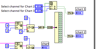
Adding control to select the input of the chart data?
I have a device which sends several channels of data via TCP. I created a (attached) VI that analyzes this data in integer multiples. Can I connect a graph (I use graphics mode band) to one of these inputs. The problem is there is about 50 channels and I don't want 50 cards of band. I would like to graphs 4-8, with the possibility to choose the input for each use of a control channel. Any ideas on how to achieve this? Thank you!
Use the table to Index. Connect the table of Boolean to the Board Index. Connect the channel switch to the Index entry. Connect the output to the chart through the Boolean primitive to (0,1).
For several graphics expand the Index table and connect the selector for each chart to a different Index entry.
Lynn
-
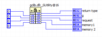
Make sure that wire you all the inputs and outputs of your node library function call?
This document says "make sure that wire you all the inputs and outputs of your node library function call.
But all the terminals on the right side of the call library node considered "outputs" referred to in the foregoing statement?
This same document continues to show the right way to allocate memory with this illustration and in the illustration, the right "outputs" are left without junctions.
Am I right in assuming that the only terminals that count as outputs, those who use the code of the DLL (modify) as output? If it is true, then all other terminals output associated with the values entered alone so don't really account as outputs, correct?
In the parameter call-library configuration screen there is a "Constant" check box and the help that he wrote "indicates whether the parameter is a constant." What is this box? for me in the setup of the DLL call
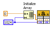
Finally, assuming that a call from the DLL that is supposed to write in these five outputs, is it legitimate to use constants like this to book a space of memory for the output values?
How about if local variables associated with the output terminals are used instead?
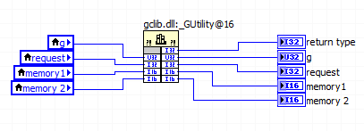
Despite the linked document, it is necessary to connect the corresponding entry for simple scalar output parameters (for example a digital). LabVIEW automatically allocate memory for them. If you do not want the entries for all the output wire anyway, there should not be no difference between a constant and a local variable; I would use a constant to avoid useless local variables.
For settings that are only entries, there is not need to connect the outlet side. It's a bit simplistic since all parameters are entered only and get one result (other than the return value), you pass a memory address and modify the content to this address, but LabVIEW manages this dereferencing pointer for you. If you want to really get into the details, learn more about pointers in C.
The "Constant" check box acts as the qualifier "const" on a c function parameter. It tells the compiler that the function you are calling will not change this setting. If you call a function prototype includes a const parameter, then you must mark this as a constant parameter when you configure the call library function node. Otherwise, I wouldn't worry on this subject.
Maybe you are looking for
-
Can a second hard drive be added to a Satellite A200-298
HelloI have a Satellite A200-298 which came with a hard drive of 200 GB, I wondered if it was possible for a second hard drive more to be added to help with Itunes that is storage of files and movies. Post edited by: Irishdiver
-
Error 1705: the dependency service does not exist or has been marked for deletion
When I tried to restart the window 2008 Server service: "remote desktop virtualization host agent" then the error of the object turned. and the client computer to outernet can not remote connect to the server, the error appeared as the below: Please
-
Original title: Ox8000700020 Hi, when I try to back up my files to an external hard drive I get error code 0 x 8000700020 how to stop what is happening
-
Suddenly, I got a popup for C++ download on windows xp. I can't find it after downloading.
I had a sudden window to download C++ and an agreement with Microsoft to accept before downloading. I accepted and downloaded - now I can't find it. I made a mistake by downloading? Original title: popup sudden to download C++?
-
On the removal of the updates of Windows for Vista
I have Windows Vista 7. If I switch to Windows 10 I continue to get automatic updates from Microsoft? I understand that Microsoft supports is no longer upgrading the Vista operating system...