Continues to draw in real time
Hi all!
I use the graph XY to plot multiple data receives serial com and I wanted to show the graph in real time. My question is, how to do from the beginning?
Thank you!
Why do you use an XY graph instead of a chart?
Tags: NI Software
Similar Questions
-
Continuous data acquisition and real-time analysis
Hi all
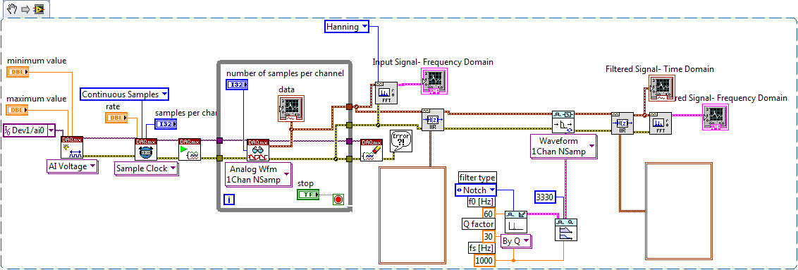
It is a VI for the continuous acquisition of an ECG signal. As far as I understand that the analog read DAQmx VI must be placed inside a while loop so it can acquire the data permanently, I need perform filtering and analysis of the wave in real time. How I implemented the block schema means that data stays int the while loop, and AFAIK the data will be transferred on through the tunnels of data once the loop ends the execution, it clearly isn't real-time data processing.
The only way I can think to fixing this problem is by placing another loop that covers the screw scene filtering and using some sort of registeing shift to transmit the data in the second while loop. My question is whether or not it would introduce some sort of delay, and weather or not it would be supposed to be the treatment in real time. Wouldn't be better to place all the screws (aquicition and filtering) inside a while loop? or it is a bad programming practice. Other features I need to do is back up the data I na file, but only when the user wants to do.
Any advice would be appreciated.
You have two options:
- A. as you said, you can place the code inside your current while loop to perform the treatment. If you're smart, you won't need to put one another while loop inside your existing (nested loops). But it totally depends on the type of treatment that you do.
- B. create a second parallel loop to perform the treatment. This would be separate processes to ensure that the treatment is not obstacle to your purchase. For more information, see here .
Your choice really depends on the transformation that you plan to perform. If it's much the processor, this could introduce delays as you said.
I would recommend that you start at any place in the first loop and see if your DAQ buffer overruns (you can monitor the rear of the buffer during operation). If so, you should decouple the process in separate loops.
In what concerns or not ' it would be considered as real time processing ' is a trick question. Most of the people on these forums say that your system is NEVER in real time because you're using a desktop PC to perform processing (note: I guess it's the code that runs on a laptop or desktop?). It is not a deterministic systemand your data is already "old" by the time wherever he leaves your DAQ buffer. But the answer to your question really depends on how you define "real time processing". Many lay it will set as the treatment of 'live' data... but what is "actual data"?
-
Since Firefox downloaded 13, my Hotmail Inbox has continued to update in real time.
I always keep a tab open for my Hotmail account so that I can see at a glance if new messages have been received. Now, I must go back to the Inbox and refresh the page.
Hello, other people seem to have the same problem. the folks at microsoft/hotmail are already aware of this bug and I hope that will come with a solution soon.
for reference, it's bug #736731 (please do not post in the bug reports).
-
How can I draw the intensity in real time of a picture in time real (imaq 1394)?
I have a firewire camera.
I hooked up my camera to my pc with labview and now I display image in real time. How can I draw the intensity of a region dependent on time?
Y - intensity
X - time... I would watch the variaions real-time intensity...Thanks in advance
The light meter example is pretty much what you want to do. It is located here:
\National Instruments\ \examples\Vision\2. Functions\Light Meter\Light meter Example.llb\Light meter Example.vi In the example, the x axis are the number of iteration, but it is easy to modify to use a graphic instead of a graph and chart the time instead.
Hope that helps.
Christophe
-
Background:
I have a table of about 10 000 points, what I need to graph. The original way that was done in PHP was to simply create a 10 000 image pixels wide and put in a box with overflow hidden and use JavaScript to move the image to the left at all times to make it look more lively. When I try to do that in flex using mx:move, the graph is too nervous. I want to go smoother. When I use only 200 of our data points in the chart moves pretty smooth for me. I tried to increase the pace and also used mx:AnimateProperty on 'x', but it seems to be the size of the image that is the problem.
Current idea:
My new idea is to have a window of 500 pixels and draw the graph in real time. The theory is that the graph would begin putting 500 points in the area of the first 500 values in the table. then, in each image, each point takes the value of one on his right and the last of them takes the next value in the table. I have not the slightest idea where to begin to make this happen or if it is still the best course of action. Any help is appreciated.
or perhaps cela?
http://www.stretchmedia.ca/code_examples/chart_range_selection/main.html
-
Filter in real-time / layer style plugin
Is it possible at all to write a plugin to filter which is applied in real time, that the user draws on a layer?
I think of something similar to the layer styles (for example, drop shadow) which are applied immediately while the user draws on a canvas. As far as I can see, there is no API to add new styles of filter, but there is perhaps a work around for similar behavior by using filters?
I want to create a filter/style simple mirror reflecting the right side of a layer on the left side as the user draws on a layer, because it would be very useful for the design of symmetric structures.
Or could be achieved using multiple layers? For example, 2 layer on top of layer 1, where half right of layer 2 is completely transparent and half left of layer 2 contains a mirror of layer 1 version? But then how could it be continually updated Layer 2 while the user draws on layer 1?
Any help is appreciated!
You can do within your plugin, as does fluidity.
But, as explained in the SDK, you can not write a plugin that lives of the updates on the document or add layer styles.
Regarding symmetrical painting - which is already available in Photoshop Extended using 3D texture mapping.
-
Problem using USB-6356 on target in real time
I try to use the NI USB-6356 on a SBC I converted to a target for LabVIEW RT. I created a LabVIEW RT project with the Architecture of Communication continuous model. However, when I select target RT > New > NOR-DAQmx channel, the wizard says "no device found support.
Here's what I've done so far:
- Installed Support in real time on the host computer.
- Installed OR-DAQmx 15.5.1 on RT target (it is visible when I develop the 'software' under the lens of RT in MAX). See Fig1.png and Fig2.png.
- Verified that the NI USB-6356 appears in max under target RT > devices and Interfaces. See Fig3.png.
Even if the NI USB-6356 appears in MAX, it seems suspicious that it appears as a USB device generic (like the keyboard and mouse that are connected to the target RT). Maybe it appears that way because it is connected to a goal of RT, but it seems that it is not recognized as a DAQmx device. I don't know how get the target RT to recognize as a device DAQmx, given that the appropriate drivers, etc are installed on the computer host and target RT.
Thanks in advance for any help!
Sorry to be the bearer of bad news, but the devices USB DAQ (other than the USB cDAQs) are not supported on PharLap targets at the moment. The documentation could certainly be clearer, so I'll update soon to reduce the confusion on this topic. This white paper, last updated in 2014 is clearer than we currently have. It is also explained in this KBQ5, but the wording is certainly a little bit clear here.
I'm not sure of any other solution that exchanging your 6356 for cDAQ USB system, or the displacement of a BONE no - RT.
-
Need information about memory in real time
Hello
I use sbRIO 9633. I save data in the memory of the sbRIO (via ftp), as well as on the C drive of my computer (via an executable).
My questions are,
1. when the RAM is emptied (in other words, I take the target), the details logged on the sbrio via Server ftp does not get emptied. Therefore, when you connect via ftp, which part of memory are stored data? What happens if the memory is full? (as the application should work for years)
2. that the application runs continuously, the bytes available on the real-time target decreases permanently (I guess) and finally RAM is full. So, do we not have to empty the RAM from time to time?
3. If I do not add the loop of the newspaper on the RT vi, will decrease the "available bytes" on RT target? If not, then how?
Hope that my questions are clear.
(1) NEITHER sbRIO 9633 has 256 MB of memory persistent which is used by the ftp... should be easy to fill, so check the case 'out of memory '.
(2) NEITHER sbRIO 9633 has 128 MB of RAM and you should read the FreePhysMem property when your application is loaded and determine a threshold to know when it's time to free the memory.
(3) this can be done by the host (PC), by logging system (ip target) required.
In my case, the memory used by the network flow increases over time, and I trigger to reset the stream to release the RAM.
It may be useful
Christian
-
NO 6356 captured data in real time?
Buenas tardes the comunidad has NEITHER.
Bueno esta are mi segunda pregunta one NOR photos of Lola gracias por the colaboracion, realmente me colaboraron muchisimo en mi pregunta anterior hasta resolverla.
Quisiera saber if con tarjeta NI 6356, are el device than hasta el momento estoy operando is can capture data in real time of forma continued, hasta el momento con the the logramos get comunidad ayuda a LABVIEW medio por programa captured datos por 2 minutos consecutive, a una frecuencia muestreo 1 MHz. Adjuntare el programa as estoy manejando hasta el momento , pero me gustaria saber if hay forma Quebec capture the information of manera continued, y poderla stop in el momento deseado, el realmente real programa indico cuanto tiempo pero su limit son 2 minutos mas tiempo types capture a message indicating that sober paso the capacity of memoria interna.
MUCHAS gracias por su Atención y knew tiempo, igual seguire realizando the tests, TR black find alguna mejora posteare o tr black resolverlo. MUCHAS gracuas a todos espero than me can help.
Carefully,.
Andres Saavedra
-
Hi all
I am trying to create a spreadsheet of the 500 columns and 1000 lines.
My program consists of real-time data streaming via the com ports (VISA), running in a continuous loop. I was hoping that someone could help me with the following:
(1) how to convert point-by-point of data in a table format?
(2) how to put in place the iterations and loops for the program to collect 1000 samples of data and then move to the next column (switching 500 times columns)
(3) how can I take my array 1000 x 500 and write it to a spreadsheet?Most of the examples that I find to create rows and columns of the tables use random number vi, incorporated into the INSIDE of a loop for, and then auto-indexation it. However how I incorporated my data in real-time (within a while loop) in a loop for (that's why I'm unable to follow these examples).
I'm new to LabView fairy. I would be great if someone could help me because I've tried countless ways to create my spreadsheet.
Thank you!
Would be easier to collect the data in a table 1 size d 500000 (= 500 x 1000). Initialize an array 1 d of this size and the correct data type and use it to initialize a shift of you register acquisition loop. With each new data point, use 'replace the subset of table' to replace the actual data based on the final iteration. When the acquisition is done, reshape the array to 500 lines. 1000 columns and write it to the file (using for example write to the spreadsheet file).
Why do you use a while loop. Apparently, you know the number of iterations before the start of the loop, a loop FOR would be more appropriate (you can view the conditional terminal to stop earlier if necessary)...
Be aware that it is expensive large format paintings. Unless the ihe file must be imported somewhere else, I recommend using binary files.
-
Hello
I'm working on a project of tension. I have read the data using the OPC. My variable is double wall to an address of mutual FUNDS. I want to plot these data to 10ms resolution. Is this possible?
I have download a code sample, I tried to solve this problem. but is is not accurate and does not.
You have an idea to plot the data in real time with a resolution of 10 ms?
Hi beginner,
you really need to redraw your project!
(1) not the OPC data source really provides new data with sampling frequencies of > 100 Hz?
(2) do you really need to draw the new data with a frequency of 100 Hz? You can't look at the graph that fast!
If 1) applies: make a separate loop to collect data at the necessary pace in a registry to offset (or any other method to store the data). If 1) does not apply: lower the rate to which you are trying to read new data!
(2) applies (no alternative): update your table with a rate of (say) 5 Hz. It's always fast enough when your field visualization and a lot less CPU consuming.
You need to separate the task of gathering data from the task of their display!
Your last question:
Any multitasking (standard) OS will involve a big Jig in your loop times. With a RT - OS this jitter is much smaller, but still different from zero. See the plug...
-
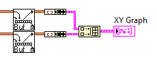
In real time several parcels using the graphics buffer XY?
Hi all. My teacher wanted to add a second set of data to the plot in real time, I've created in my vi. I was able to trace the two sets of data, but not as two plots. I managed to add a second point of y to the plot. What is the appropriate method for the use of a buffer of xy-graphic inside a loop to draw two separate parcels?
The idea is that once I have two plots I can adjust a second axis and adapts the second group of data to this axis.
Thank you!
Nukem,
LabVIEW 2010
PS. Here is a picture of the small section of my program which is graphically representative data.
-
Hearing feedback in real time program: hardware configuration
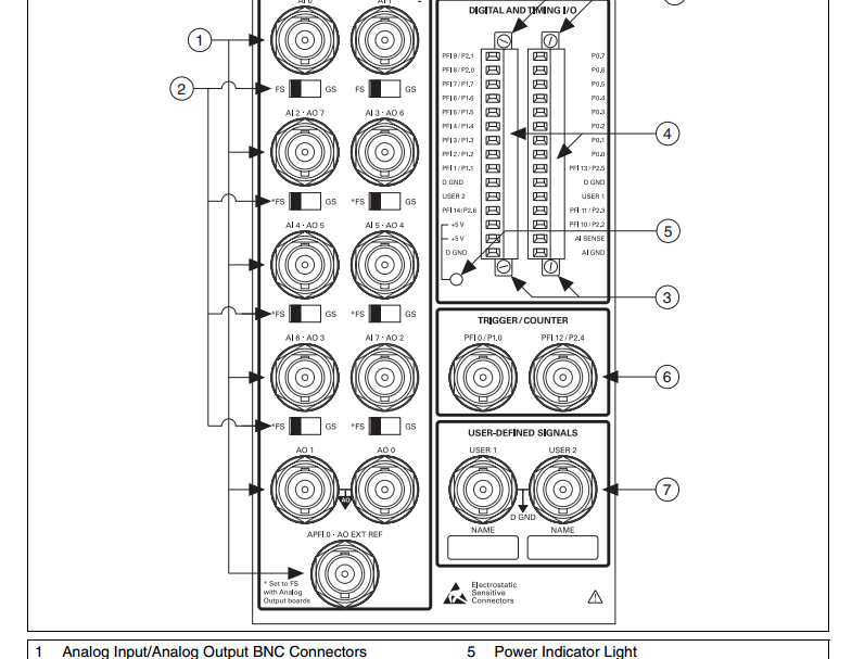
We had access to a LabView (of another laboratory) program that records the sounds and gives audio feedback in real-time based on the analysis of the spectral structure of the input sound. The current combination of equipment that we have in our lab is the Daq 6259 PCI card and a BNC-2110 connector. The laboratory of donors had run a set consisting of PCI 6221 Daq card and connector BNC-2090. I'm studying the manuals for the four pieces of hardware to determine if our hardware configuration can be used with this LabView program. The main difference I found is that the connector BNC-2090 has DACout connectors, which lacks the BNC-2110 (my setup). I don't know if that alone will make it unnecessary for use with this LabView program.
I continue my study of textbooks to go further, but it would be useful that some experts could give its opinion on it. In this way, I could do a faster purchase decision.
Thank you!
Anand
Hello Anand,
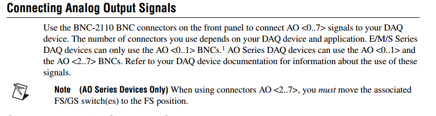
2110 has analog output BNC connectors that expose up to 8 channels of analog output on your Data Acquisition device. Please take a look at the below picture of the BNC-2110 (page 3) user manual and following section which discusses the analog pins output BNC (page 6).
Best regards
Izzy O.
Technical sales engineer
National Instruments
NI.com/support
-
problem while conspiring waveform of the signal in real-time
Dear Sir
I use LabVIEW8.2 and USB1208FS for data acquisition. I have configured hardware with LabVIEW and data in real time using the Universal Library VI AInScBg.vi. When I draw my signal on the waveform (amplitude vs. frequency) then on axis x frequency ranges from 0 ~ 0.49 hz. I have change the sampling rate of 1000 Hz to 4000 Hz, but on the x-axis without frequency change occurs and it is set at 0.49 hz. Can you please guide me how can I get the frequency of my own interest on the x-axis.
I enclose you daughter of LabVIEW for reference.
Kind regards
Muhammad Irfan
Student
UTP Malaysia
0060149087570
Simply change the text label of the x-axis of frequency does not automatically the correct calculation. You do not pass in the sample information in the service spectrum, so you get no frequency information. You can see the strain on the entry point. The function expects a data type of waveform as input. Without it, the dt will default to 1. Then, use the function create a waveform and add information from dt to it as well as your table of Y.
-
& quot; An error occurred while installing LabVIEW Real-time 2009 (in English). ...
While trying to install the real time of the third quarter of 2009 DVD module, I get this error message.
"An error occurred while installing LabVIEW Real-time 2009 (in English). Do you want to continue installing remaining products? »
After removing the program OR series (USB) 1.1 installation completed up to the end. If you answer no to continue to install the above question, the following error message refers to abduction OR Serial.
Maybe you are looking for
-
Save indivifdual emails directly on the drive?
I need to identify and save individual emails (identified using the filter function) to a folder in the disc. To ensure that no e-mail is overwhelming any other file names could be (possibly) self created GUID, otherwise the line object (adding a cou
-
In Outlook Express, there is no longer a noise when I get an email.
AT OE. Recently, I lost the sound for incoming mail. Have tried to reset but nothing seems to work. Any ssuggestions, please?
-
I am running Windows XP Media Center, with a Windows Media Center extender. As part of the installation, the Microsoft software is installed an Extender resource monitor - if the monitor is in the red, you might have some performance issues with you
-
up to date kb/2680317 failed with the error code 646-how can I fix
How to fix update does not install and error code 646 kb/2680317
-
Get the green screen on Windows Media Player
To the right; I get a green screen on Windows Media Player while trying to watch videos online. The version of the media player is 12.01.7601.17514. Please notify. Thanks in advance, Ted Chalkidis