Could use labVIEW c#?
LabVIEW can use c# in the .NET environment?
LabVIEW can call .NET assemblies. For example, if you compile the c# code in an assembly, then you can call using the .NET features. There is a section using LabVIEW on the appeal of .NET assemblies, and there are shipping examples as well.
Tags: NI Software
Similar Questions
-
Time real ADC/DAC for SMPS by using Labview and USB
Hi all
I asked the Sales Department of this same question, so here's a two-pronged approach:
I am reserching a control algorithm for power switching, and so far, its performance simulations seem to be good. Now, the goal is to implement the circuit from the experimental data.
I've seen several NI USB DAQ boxes that seem to have the performance, I'm looking for (for example, the box USB-6211 a sampling rate and resolution I need).
The control algorithm uses the following mathematical functions: add/sub/mult/div/exhibitor and derivative/integral.
My question is this: is "strong enough" Labview take four-channel data 250Ksps, crunches the numbers in an equation and spits out the answer to an analogue on the channel, while time REAL? I'm looking for a rate of analog output of ~ 100 kHz.
Thank you for any suggestions you have!
-Rick
Hey,.
So if you were trying just to perform an input or output, then the box USB-6211 would certainly be able to treat it as the machine clock could manage the inputs/outputs, no software. However, what you are wanting to do, basically a feedback system, he will have to avoid (at least to a USB device) because you need to be able to specify Active which is the output. So, for this reason alone and the fact that you want out of 100 kHz, this device and the USB devices in general will be not an option any what software you use, LabVIEW or otherwise. On another note, you want to make sounds more like live update, not in real time, which is more on the jitter. Bottom line, for these kinds of requirements, you might need to move to an FPGA card, something like the NI PCIe-7841R would work. It's more expensive, but for your needs, FPGA will be the only option and it comes down to the latency of the bus, but also the response time of software. With FPGA, as shown in the first scheme of the following document, you basically close your software through hardware loop.
Basics of FPGA
http://www.NI.com/white-paper/6983/en
-Ryan S.
-
How to view mdsplus data using labview
I posted this question in the Council of Labview, but seems that nobody does it so far. I don't know what is the best place to ask this question. So I reposted here. Thank you very much.
I am a newbie to Labview. I'm writing a few vi to display and write data to Mdsplus. I downloaded Mdsplus(labview) can discover Mdsplus functions, like mdsconnect, mdsput, ect, in vi to call a library function. But I have no ideal how to use it. I tried to use the Mdsconnect function to connect to a machine, but it still gives me an error like: Labview: an exception occurred in the external code that is called by a call library function node... I was looking for help on the internet documents, but could not find anything useful. Could you please help me with this problem? If you have examples of these vi, or teach me how it, it would be very useful. I'm using Labview 8 (windows). I would appreciate your help! Looking forward for your reply.
Oops,
I attached properly in the previous post.
Greg
-
Deal with failure when using LabVIEW 2011 and DSC MODBUS communication
I'm currently reading from operating records a PLC with MODBUS/TCP. I confirmed that the PLC will update the values and in response to a MODBUS communication correctly by using a third-party program called Modbus Poll. However, when I try to query the PLC using the LabVIEW shared variable engine, I am unable to read the values of the same addresses that I consult with Modbus Poll.
My installation is simply to a PC directly connected to the controller via Ethernet without a router between the two. I'm using LabVIEW 2011 SP1 with the DSC module.
I opened the Manager of distributed systems OR to display the State of all variables in the Modbus Library that I created, and I noticed that the ILO CommFail permanently the value 'true '. All other variables with a 'read' access mode signal "failure of process". I tried to restart the process and stop and start the local variable engine without success. I also restarted my computer several times to see if any services did not exist, but this does not appear to have solved the problem.
Finally, I resorted to listening to communications on the network card I have the PLC connected via Ethernet using Wireshark and found that while Modbus Poll communicates with PLC, number of MODBUS and TCP packet is sent and received. However, when using only LabVIEW or the DSM OR communicate with the controller, there don't seem to be any communication on the network card.
Something that may be interesting to note is that I could communicate with the PLC and to read values with the DSM just once, when I understood everything first what address I should be reading of. All of this has stopped working shortly after. Prior to this, 'CommFail' was not generally set to 'true' with my current setup. Thinking it was my firewall, I have since disabled my firewall, but this seems to have had no effect on the problem either.
Any help on this would be appreciated.
So, I thought about it. It turns out that the IP address of the server i/o MODBUS must be set to the address of the MODBUS slave, not the local computer. The address of the i/o MODBUS server is defined by the navigation in the Explorer window projects, expanding the variable engine shared library for MODBUS and right click on the server MODBUS (for example Modbus1) item and select Properties.
In addition, the addresses seem to be shifted by + 1.
Thanks for the tip so.
-
Go to the PHP website using Labview 8
Hi people,
I'm writing a vi LV8 to retrieve data from a Web site. The first site I've played with just had a text output so a simple:
-OpenTCPConnection (for 'www.hpc.ncep.noaa.gov')
-WriteTCP:
-line 1: 'GET heat_index_MEAN/hitable_east.txt '.
-line 2: "" Host: www.hpc.ncep.noaa.gov".
-line 3:
-ReadTCP
It worked perfectly fine.
But this isn't really the data I want. I want the data displayed on the Web site:
http://forecast.weather.gov/MapClick.php?W0=t&W1=TD&W2=Hi&w3=sfcwind&w3u=1&W4=sky&W5=pop&W6=RH&W7=th... 96 & textField2 =-77.48167 & site = all & unit = 0 & dd = 0 & bw = 0
But, when I try the same calls I get the error messages like:
Query HTTP/1.0 400 Bad server: AkamaiGHost Mime-Version: 1.0 Content-Type: text/html Content-Length: 216 Expires: Sunday 12 August 2012 17:40:25 GMT Date: Sunday 12 August 2012 17:40:25 GMT connection: close
Bad request Bad request
Your browser has requested that this server could not understand.Reference #7.9f931160.1344793225.0
I don't know enough about HTML or PHP to tell if I have a HTML or PHP problem; and what I have to understand to move forward. More precisely:
-can you tell if it is a PHP or HTML problem in my code?
-If Yes, which?
-I can access a Web site (which uses PHP) LabVIEW?
-what I have to learn more about PHP to proceed?
-J' tried to send a command "OPTIONS" of HTML, but I received very similar eror messages (not a quesstion)
-the site has an XML option that displays data as text/XML, but it also seems to use PHP, if I get the same errors with my code (not an issue)
-any ideas on how to use labview to read data from this site?
Thank you, in advance...
-
Strange behavior when using Labview to collect data from Tektronix oscilloscope tds8200
I hit a wall in trying to understand this one. The problem I have is that my application will not start the oscilloscope when it should.
I use an oscilloscope Tektronix TDS8200. My goal is to collect data from the oscilloscope using Labview waveform. First of all, my program initializes and configures the oscilloscope; This part of the program works very well.
The second part of the program begins the acquisition of data with the function 'Tktds8k Start or Stop Aquisitions.vi', which is to press the button run on the scope. The function "tktds8k to Waveform.vi" is used and should ideally return data, which I connected to a waveform playback graph.
When I run my program, the first part runs without a problem, but as soon as the program comes to the service get the waveform, the run button in the scope, which is green when running, turns off; the program then expires, and no data is collected.
Here is where it gets weird. I went through the debugging to try to understand this point, and I put breakpoints on the beginning and get shape wave functions so that I could scroll through the last part of the program. The program continues with the departure function, and the button run in scope is green. The breakpoint for the function get the waveform is reached and when I press on continue, turns the Run button and turns it off then back on almost immediately. data are collected, the waveform graph appears and the program ends without error.
I thought that the timetable could be the problem, so I did the program wait as long as five seconds between the functions of start and get the waveform and that did not work. I also tried to move the start function to before the configuration functions and remove start completely; no method worked.
is there any ideas on why, the program works when I enabled breakpoints and isn't when breakpoints are disabled? I'm sure there is an easy solution, but I was not able to find a solution.
I have attached a pdf that contains information about the functions of the Oscilloscope (tktds8k.pdf), and I have also attached my program.
-
Interfacing Ensenso SDK using labview
I am trying to Ensenso SDK interface using labview. The company provides a .net dll, however, all available functions are not accessible from labview. They also said that labview is not yet officially support for interface with the Ensenso SDK. But C, C++ are officially supported. Now my question is, is it possible to write code c or c++ to control the Ensenso SDK and then access the C or C++ works using labview? If so can you help me how can I do? Thank you very much for your support.
With sincere friendships.
Sewyew
If you can not get the .NET DLL to work with LabVIEW (for example the use of the call library function node), you could create a C/C++ DLL wrapper that allows you to access the functions you need. I don't know too much about the details, but it is certainly possible.
-
NEITHER CVS using Labview Linux?
Hi, I have a CVS here, as well as 1455 development under labview linux machine. I've used MAX to set up this CVS, but it seems that my labview is not MAX, and I can see on the site it seems to be available for Linux. Could someone point me in the right direction to set up/use my CVS using labview linux (I've got installed 8.5).
You need to write code CVS to turn an image into a table of number using IMAQ ImageToArray.
Then, use the shared variable or TCP/IP to return data to the host VI.
However, there are two things to remember:
1. an image won't be like in real-time, as show on VI target itself.
2. because the Vision Development Module does not support on Linux, all the processing of the image on Linux must develop in yourself.
-
reading photoplethysmograph waveform with serial port on PC using Labview
Hello world
I'm gaining time real Photoplethysmography waveform of serial port using Labview.I have managed to acquire data from serial port by using the following features:
-Baud rate: 38400
-data bits: 8
-stopbit: 1
-No parity bit
-Time delay before reading the serial port: 10 ms (according to what was written in the manual that every 10 ms there is a frame in serial port)
After the reading string will be converted to byte array to be able to extract the bytes associated with waveform (1 & 2 bytes in a frame) even for SOP2 (6 & 7)
(what is read in serial port is in decimal and must be converted to hexadecimal based on what made the software of prodeuct for some result.that in the waveform properties, I chose the hexadecimal representation)
Then, as mentioned in the manual, I associate these two values to draw the waveform.
Although I used the filter band digital waveform of pulse but not significant pass that was seen (cutofffrequeny:10 high low cut-off frequency: 0.5).
I have attached my program and result in front of Panel and manual for the sensor. The result is still far from what is supposed to be. I was wondering if you could help me and let me know your opinion on the program and the protocol used. I have to get the result as soon as possible. Please let me know if you need more information.
Kind regards
-
Hello
You have an idea on how to receive SMS using labVIEW? I tried the AT commands using hyperterminal to receive the SMS, but I do not know how to continue on labVIEW to receive?
The concept is same with the sending of SMS in labVIEW?
Thank you

Hi MiBL,
If you could do this using AT commands, it is the same in LabVIEW so. Use the VISA, write the commands using the functions of writing to the modem and play the same thing using reading orders. You can even find examples for this if you search the forum properly.

Kind regards
Amine31(Bravo to give good answers, mark it as a Solution If your problem is resolved
) -
AKM21C using LABVIEW servo motor control
Hello
I'm controlling only 3 engine AKM21C using LABVIEW. I want a user to enter a certain length and width to move the motor in x-y-directions, and through the GUI LABVIEW on the façade. Two of the engines must evolve synchronously in the direction, while the third engine moves in. x I have a query UMI-7774 interface connected to the reader of the AKD engines.
Could someone please guide me on how to proceed with this?
Hello
Assuming you are using one of our motion controller cards, follow-up guide will be an excellent aid step by step to get you started: http://www.ni.com/pdf/manuals/375543c.pdf.
-
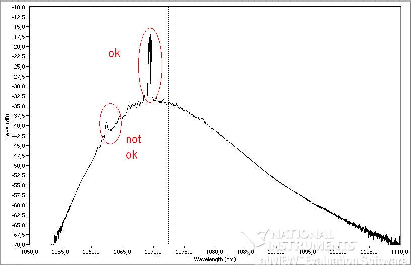
How smooth a XY chart by using Labview 6i?
Hello
My main Vi captures the data that I sent to a XY graph
I would like to smooth out the curve before and after ('not ok' on the photo) the main peak ('ok' on the photo)
I looked for aboard or and have not found anything that I could use with Labview 6i
Does anyone have a solution?
Thanks in advance
See attached simple vi with data and graphics
There are several options:
- Use the filters in the range of Signal Processing to smooth the data.
- Fourier filtering techniques to smooth the data. Fourier transformations are also in the range of Signal Processing.
- Use almost any technical standard smoothing. To view the online version of the Numerical Recipes many methods. You will need C in LabVIEW, but it's pretty easy. Savitzky-Golay smoothing is especially good for this type of problem.
You will need to convert your XY data to waveform to get one of these at work. If you data are spaced regularly, it's pretty easy. If they are not, you will need to make some kind of interpolation. Or you can simply ignore the fact that you have unevenly sampled data, convert a waveform, smooth, then convert back.
A word of warning. The 'not OK' part of your waveform seems to have important characteristics. Putting my hat physicist for a moment, are you sure you want these pics gone? This is also true of the myriad of small peaks around the main one. Be careful. A better approach might be to eliminate differences in gain in order to have a flat bottom (1060nm region - 1080nm), and then try to model the peaks of interest. You could also take multiple series of data and to get rid of some of your sounds, average your X-scale condition is stable. But it really seems not to be much noise on these data. Most seem to be important.
-
Screenshot of Tektronix MSO4104B using LabVIEW
I am trying to acquire a screenshot of an oscilloscope Tektronix MSO4104B using LabVIEW. I am currently able to collect data from the device and have a waveform displayed on my front of VI. However, for various reasons, our preference is to capture the actual screen shot of the scope.
I have reviewed the reference for programmers for this camera and have done countless searches on Google for an answer, but have not been able to find a solution. It seems that a few people were able to reach on OTHER Tek scopes by sending a hard copy through the port of communication (GPIB, USB, Ethernet, etc.), but according to the reference of programmers for this particular device, it seems that he will send a paper copy of an installed printer, rather than simply as a stream of data to the port which can be read using VISA controls.
The other solution I've seen is to record the screen turned to a flash drive, and then copy the file via the port to the PC. However, none of these solutions seems to be available on this device... it's one of the more advanced scopes makes Tek... I can't believe it's so hard! Help, please!
-
waveform, with an average of results using labview to O-scope
Hello fellow engineers! I'm a first-yeargraduatestudent in CHEE at the University of Houston. Basically, I know nothing about labview. I am trying to program an application that looks like this - I collect a waveform of the signal of O-scope. This waveform does not change its characteristic shape. I need to find the wave form average of waveforms of N (100 for example). Thus, the slight changes (or noise) in the feature of form during the period mustbeaveraged out and I need to have a resultant waveform that represents the average waveform over a period. So, basically, I'm collecting the wave several times (for example 100) on a single period. The O-scope that I use now is Tektronix TDS 2024 B. It communicates with the computer via USB. The version of labview is 8.5. For now, I am able to communicate with the computer using our o-scope through labview. I already downloaded the driver of instruments of your Web site. It turns out that the program can give me only the average result I can get directly from o-scope manually. I need to have more say on average (100) using labview. I wrote a program that relies on the instrument driver that is downloaded on your website (for loop part is average, the waveform). The program that I modified and an instrument driver are attached. The program cannot be fully open, if the driver is not put in the right place in the labview (under lib inst.) When I run the program, the average waveform does not appear on the front panal and signal waveform file is not saved correctly. Is there someone can find where I did wrong and it develop for me? Because I barely know Labview, it will be even better if you can add an image or program that you have changed. I'm waiting for your creative ideas.
With the best regards,.
--
Weiye
-
I want to send data using labVIEW to arduino using write visa and the process and to take action using arduino. After that, I want to arduino to send out necessary via a serial port to labVIEW which should be read using visa read and store in a chain. While I am able to write or read both individually, I can't do it consecutively. I used advanced read and write vi for checking my code, but nothing is helping. The wrong bed 'time delay before execution. " Please let me know where I can go wrong. Also is it possible to write code for hx711 using labVIEW
1. you need not "\n" on your orders println(). This command adds an end of line character already in the message.
2. you get the error because you have a loop around your reading. After the first reading (well technically, the second because of you add an extra line end character), there is nothing left in the port. As a result, you will get the timeout.
3. you should really consider using a Structure of the event. This way you just don't write and read when you press the Write button and you can also use the structure of the event to make the loop to stop. I also go up to close the port inside the stop-> value Change event.

Maybe you are looking for
-
Turn off Spotlight search in iCloud drive
I have over 40 GB on my drive to iCloud and whenever I am connected to the Web, kernel task uses all CPU. I suspect that Spotlight indexes my iCloud drive and check, I tried to put the iCloud drive in the folder to be excluded but could not find a wa
-
Cannot export the song on iTunes...
Can anyone help? I'm just trying to 'share' a song, he, export to iTunes. Have done several times in the past now, it just sits on the 'conversion' forever and I have to force to leave out. What happens with GarageBand now?
-
a HP deskjet dj2540 e-print is enabled?
I just bought a HP Deskjet DJ2540 to connect to my Toshiba Chromebook. There seems to be confusion in the HP website, some pages say yes a DJ2540 is active e-print and other pages say that it is not. A DJ2540 is renamed as direct print enabled, but
-
How to change the acquisition on GigE Camera settings in VBAI
I have a line scan application where I need to control the rate of the line depending on the speed of the machine. I use Vision Builder (Vbai) 2009 and I have Labview, but not the Module's development of Vision. I use a custom Labview User Interfac
-
You want to buy a copy of the upgrade to windows 7.
You want to upgrade my windows XP computer to windows 7. I found the link that I can buy. Question: this outfit sells copy of the upgrade to windows 7? (Don't want to get cheated and lose my money.) http://www.softdirectworld.com/Microsoft-Windows-7-