cRIO, modbus, DECS and Micom relay
Hello
I am keen to talk to the DECS 200 and 300 DECS and also devices Micom relay. I need Modbus to communicate with them. I understand that I can use a cRIO as a slave, but is it possible to use a cRIO as a modbus master so I can request data from devices?
Thanks in advance for answers
Hi JChec,
In fact, you can configure the server of Modubus of e/s on a cRIO as a master Modbus or Modbus slave. I enclose a window here where you can see how these options are selected.
Tags: NI Software
Similar Questions
-
OK to mix 'of connection to the switch"and"close relay switch?
Hi all
I'm developing a test sequence using the card multiplexer 2527 to the track signals. To configure the card, I use DAQmx switch functions. In my application, I have a Subvi routine that imports the data from a spreadsheet Setup and run a loop for to set the configuration for each step (each iteration of the loop contains the channel for 2527 card information). The topology is set on the first iteration, as well as the configuration of the path to the first string.
My concern is this: I need to close the extra channels/relays without changing the topology or resetting the device. In the first round, I use "connection to the switch" function to set the initial path, (ch0 to com0 for example). Then in subsequent iterations of the loop, I use "Relay close switch" function to close the additional channels individually (for example k2). In the end, when the measure is taken, both ch0 ch2 must be closed and routed to com0. This implementation is so sure, or am I somehow to make the adjustments to the initial loop?
I would like to test this with the hardware, but it is not yet available.
Also, I realize that I could use independent topology and configure all relays individually for each step, but I hope that my approach will be easier and safer.
Please notify. Thank you.
GSinMN
Hello GSinMN,
It's OK to mix 'of connection to the switch"and"Close relay switch"If you understand what's happening below. "Switch Connect" connects two channels by closing a path of relay between the channels, then "Close relay switch" can be used to change the State of the individual relays. If you are not careful you can mess up your connection by activating / deactivating relays that are part of the route connecting your channels.
"Also, I realize that I could use independent topology and configure all relays individually for each step, but I hope that my approach will be easier and safer."
I would recommend the topology independent if you want to stick with connections to channels only. http://zone.NI.com/reference/en-XX/help/375472G-01/switch/2527_independent/
Initial connection:
CH0-> pcom0
pcom0plus-> icom0plus
pcom0minus-> icom0minus
icom0-> com0
In each future iteration just connect to the next to pcom0 channel (which will be indirectly connect it to com0):
CH1-> pcom0
CH2-> pcom0
...
...
Jarrod
-
Use cRIO module NI 9477 as relay to provide 24V input for Siemens S7 - 200 (CPU222)
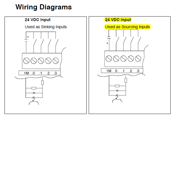
Dear all, could someone please confirm my use of NI 9477 as a relay works or not with the following details. It might be stupid question, but I do not know it is not displayed before and I can't really afford to burn my modules. I have two concerns, it's sink or connection to the source, another is the question of overcurrent.
The Siemens S7-200 is used to control an engine not by sending impulses. I provide two digital signals to control the direction of rotation of the motor. So I propose to connect my NI 9477 as illustrated in the graphic below (left configuration) relay switch.
According to the data sheet NI 9477 (attached), I suppose I should connect it as the right configuration for NI 9477 sinking module. However, power running electric in the control cabinet is wired as a configuration on the left. I don't know if I can connect to my NI 9477 or I need to set the polarity of power supply.
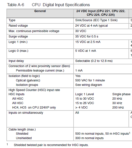
Another concern would be the current that runs through NI 9477. He rated at 1 a and will be connected in series with only a power supply 24VDC input digital s7 - 200. I don't know if the current could be a problem as in s7-200 datasheet, it seems that the current is only 4mA. I'm reading this correctly? I've also attached the s7-200 Datasheet if you have time to varify that, please.
Thanks in advance for any help.
Kind regards
Jinyu
Personally, I would just change a 9476. 9477 module looks like it's better for negative logic (24V = FALSE, 0V = TRUE).
And running for the PLC is practically in the noise of a digital signal of 24V, so I wouldn't worry on this subject.
-
OR handset and other relays in the direction of the switch
Hello
I am beginner in products OR and now I want to solve a problem.
If I know the relay and their connection paths. These relays are of NEITHER and some other producers. Can I Switch Executive put first and last point and automatically will join them using IVI drivers? Relay cards and theit drivers can be of different producers.
Thank you.
Sorg,
As crossrulz said if you have a correctly installed and configured (in max) IVI driver Executive OR Switch can manage several types of products. This includes switching modules of NOR and switching of third party modules.
To implement automatic routing, you may need to do additional things (such as: providing the report to show how the devices are connected, lines reserve for routing, put in place by the endpoints channel configuration, etc..) Once this is set up, then you can create a connection by specifying endpoints and it will automatically route the things for you.
See you soon!
-
I use the MODBUS library and can receive data, but I can send it very well?
Hello
I use the Modbus Library to communicate with a VFD to control a fan. I use the master write and read vi. I can write data to the drive mechanism and get the fan to do what I want. The VFD is supposed to send a package of confirmation after I told him to do something and I can also read its records. When debugging the VI it shows that the problem is that the buffer always reads zero and the VI timesout. If I look at the USB adapter lights to RS 485, I use to interface with the drive mechanism, I see that the flashes of light RX immediately after I send a message. So I should have something in the buffer. Does anyone have any suggestions?
Aaron
OK, here's what has happened to those who have this problem. In the series Receive.vi MB The bytes to the Port of property node has been reading 0 even if there was something in the buffer. Executing the program was then stuck in a loop until it expired and never went to read anything of serial port buffer. I didn't spend too much time wondering why that VI has not worked and created my own. Within a period appropriate after writing to the serial port, I used the same bytes to the Port property node and was able to get the exact number of bytes to the stream and then VISA vi the number of bytes to read. I received the message of the right answer and everything seemed good. But of course that NO! Then I experimented with different speeds of writing to the drive mechanism to get the fan to operate at different speeds. I found a small range of speeds where I get no response to the VFD, either in operation or by sending me a response packet. After a while, I found that there is a mistake in the LRC-8 code in the MODBUS library OR. It does not prescribe that the LRC will be a two-character value. So if your LRC is proving to be a single character such as F value (which should be 0F) you get an incomplete MODBUS message. This has been easily corrected in the vi LRC8 saying "number in hexadecimal string" vi to produce output with a minimum width of two. Then everything worked fine. Moral of the story, it's the MODBUS library is awkward.
-
I want cRIO to start and stop the acquisition by push physical button on the cRIO, is this possible?
When you use my cRIO 9024 on the ground, I prefer to be able to start and stop the acquisition with pressing a physical button on cRIO.
I want to say I don't want it to be "as a start-up," I don't want cRIO to start the acquisition as soon as the power supply is ensured.
Is this possible?
Hi Cashany,
you will surely find this switch status. But there are easier ways (but more expensive) for a button. Fiddling with a pen or a small screwdriver to switch USER1 is not what I call "user friendly"...
-You have at least 2 voltage inputs on your module available. Use a switch voltage on the power inputs. Use a 'real' button!
-You have an available serial port. You can set some pins on GND or voltage and check their status inside the cRIO/RT target...
-
Compliling VI in LabVIEW with cRIO-9004 controller and chassis cRIO-9104
I tried to compile in LabVIEW with cRIO 9004 and cRIo-9104 connected.
It has three options
(1) use the server local compilation.
(2) to connect to the network compile Server
(3) to connect to the service of LabVIEW FPGA cloud compile
But I'm unable to compile my program using one of these.
How can I get my compilation made? Help, please.
Thanks YouCp
Service provider shared's Standard Service program is an annual fee of NOR, which in turn allow you to update your modules and LabVIEW and benefiting from the support of NEITHER.
-
Modbus TCP and Beckhoff BK9100 registry/address of e/s / c
Hello
I read this thread and it helped a little, because at the beginning, there is the same problem.
The problem is that I'm trying to but it didn't work.
I use the Modbus Library of nor and the MB Ethernet Master and Slave example. I have the communication if I write the IP address in the box because COM led flashes. But I do not know what records I have to write. Where can I find out what registry/address my have. I do not understand how to address the DO. I know it's a basic knowdledge, but I don't get it and its driving me crazy.
IAM happy for any help
Hello
Thanks a lot for your help and advice.
I solved the problem by changing the output Terminal.
Greetings
-
Modbus (RS485) and automation direct example GS2
I'm looking to see if someone has used the GS2 Direct Drive and LabView automation and has a VI workign? I searched on Modbus over RS485 that uses the GS2 and I looked at the .vi Modbus Library. Correlate all that in a single coherent thought seems to have escape. I'm new on LabView and never seen before Modbus and I have a calendar that is very short to get something. Even if all .vi did was to start and stop the engine, I would be happy. Then I could set up the rest.
Figured it out finally. I have attached two VI. Read records and one for write to registers with notes on how to stop and start the car.
Thanks for the help.
-
cRIO, Webservice (REST) and front panel
Hello
I created a few simple webservice screws for greater application that runs on a cRIO. The webservice screws can be used to send simple commands to the application and give your feedback. So far, I used a LV frontpanel for interaction with the system, but for several reasons, I am looking for another way to do it.
It worked well in the development environment. After deployment webservice screw they have communicated with the application according to the needs and I am able to control the system using simple URL typed in the browser's address bar. Later, I will add static content, but for debugging, it is fine.
The thing is that now I have compiled and deployed the application, and now when I try to open the front panel I get this error message:
"VI requested is broken and cannot be read or controlled."Previously I did not use the Web OR Application Server, so I installed to use the web services. Are there conflicts between a Web application server and remote server Panel? Any suggestions on how to proceed?
I use LV 2012 and NI RIO 12.0
Best regards
Simo
Hi Simo,
If I understand correctly, you have the following configuration:
cRIO with a Web Service of LabVIEW and several Web Service screw
Some ways to debug deployed screws of LabVIEW Web Service are:
You can have the Service of the Web of LabVIEW deployed in debug and debug remote Web Service of LabVIEW desktop.
You can use a tool like factor to make it easier to apply and test your Web Service screw (similar to go to the url in the browser).
You can create LabVIEW screws of office using the Palette of HTTP Client to test the Web Service.
You mentioned the following"I have compiled and deployed the application, and now when I try to open the front panel... "
I'm a bit confused as this front panel you open. For example, do you mean that a LabVIEW project has been opened on the desktop, the Web Service of LabVIEW in the project has been deployed to the target of RT cRIO, and now, when you open the Web Service screw on the desk to look at the front panel, you get an error message?
-
Hello everyone - I am considering the purchase of a unit of WRT54g. Have a question...
I intend to have the IP-side WAN to give it to me via DHCP from ISP. I expect that the ISP will provide info server DNS as well on the WAN side.
Is it possible to pass transparently this DNS information to my LAN using DHCP clients? I'm not statically configure DNS for DHCP clients on the LAN side. I'd rather them use some address DNS is given to the router.
Is this possible?
Thank you
ScottYes. This is the default behavior. According to the version of the firmware on the server and the router DHCP on the router either directly affects the DNS of the ISP servers or he assigns the DNS relay router, i.e. 192.168.1.1 aka it's own LAN IP address.
-
NOLOGGING with DEC and RMAN incremental backup
On the 31 of every month in most of our patterns, we recreate a lot of tables using DEC.DB Version: 10.2.0.4 OS : AIX We use RMAN for our backup scheduled via cron. Retention Policy : REDUNDANCY 1 Type : Incremental
Due to the size, the CREATE TABLE instructions take a while. Because we run on the Standard edition, we cannot use the PARALLELISM.
NOLOGGING is the only option to improve performance. But we are concerned the roll forward not being generated for these tables and the potential loss of data in case of crash.
Currently we take a Level0 backup every Wednesday and Sunday night and LEVEL1 backup on the rest of the days.
I know that all will be saved on Level0. But what happens if 31 falls on a day which occurs the only backup of level 1. We will be safe only until the next Level0 arrives.
No work around for this?HI T.Boyd,
NOLOGGING is the only option to improve performance.
So no recovery will be generated but the blocks in the data files will change.
But what happens if 31 falls on a day which occurs the only backup of level 1.
Only blocks changed since the last level 0 (or level 1 if you use differential differential) will be saved which includes blocks modified by the ETG.
No work around for this?
No need for a work around. You can check at any time whether a certain activity nologging will compromise a restoration with < report="" unrecoverable;=""> .
Kind regards
Tycho -
cRIO-9118 FPGA and or cRIO-9022 RT.
Hi all.
Having trouble to get my design FPGA compile for the target.
The error is the overuse of the DSP blocks. 64 available on target...
Do I have to reduce to a minimum the number of blocks of multiplier?
Or can I somehow multiplex on DSP minimixe DSP multivariate use?
Thank you.
FPGA high speed multiplier Math must be set to LUT and not AUTO, because it will use DSP and not LUT car if there is too little of DSP.
This will reduce use DSP, but increase the use of LUT.
-
CRio-9014, 9116 and 9870 - series write does not
Hello
Yes, I was able to get things going according to my needs. There was a problem with the connector DB9 not wired correctly and Blayne Kettlewell, ELP Engineer at National Instruments helps flatten out. We are in business.
Thank you
Ajay
-
Problem of calculation calculator programmer mode
It seems a 'bit' hit and miss, sometimes it seems to give the right answer, and at other times, I get the result of-1. I guess it's my fault and error of my own operation. It would be good if it was always wrong or always correct.
Maybe it's a "bug"?
How to report a bug to microsoft?
http://www.Google.com/search?q=report+a+bug+to+Microsoft&RLS=com.Microsoft:-AU & ie = UTF-8 & oe = UTF-8 & startIndex = & startPage = 1Reports of incidents for Microsoft Technical Support
http://ampalliance.org/blogs/Microsoft/archive/2007/08/28/incident-reports-for-technical-support-from-Microsoft.aspxMicrosoft Product Support reports
http://www.Microsoft.com/downloads/details.aspx?FamilyId=CEBF3C7C-7CA5-408F-88B7-F9C79B7306C0&displaylang=enPerhaps also you can sit on an alternative for your calculations.
I see that it is causing you concerns from your previous post here, who also has no answer.
Question of the calculator of Windows 7 in programmer Mode
http://social.msdn.Microsoft.com/forums/en-us/isvwindowserrors/thread/1cc66cc9-E82C-4FCC-8e70-28b8f7c2ef41
Maybe you are looking for
-
Dear Sir. I got my new laptop Hp G6-2313AX by flipkart, It came with a default value of BACK - BONE, When I try to reinstall the OS its error message indicating that the drivers are missing hard drive, m I checked the bios Setup that I have all the i
-
cluster to table 1 d of clusters?
I inherited a LabView program that I'm trying to work on a new version of LabView and I ran into an error that I can't fix: These can be wired together as their data types (digital, string, array, cluster, etc.) do not match. View the contextual help
-
Installing not KB2288608 and 2509461 KB event log reports.
I get errors on my event log saying that the updates above is not installing on my computer. Is there a way to remove the facility?
-
BES 4.1.7 OTA application WebWorks - camera problem
We build a webworks application, using sdk webworks 2.3.1 for OS smartphone devices. If we push the application manually in a dev machine to the phone via a usb cable, we are able to take photos and the photo stream app. Our problem is that if deplo
-
With respect to the ether channel
Hi friends, I have a few basics of manufacturing of switch ports 1 Channel eil. I just want to know something. I have 4 switches from cisco 2960 to which many users are connected. None VLAN are that the only default vlan 1 is here. Now I want to make