Custom signals DAQ
Tags: NI Hardware
Similar Questions
-
generation of signals DAQ 6133
Can use of BNC-2110 and DAQ board 6133, I generate a sine signal and the signal sine output?
Hi WG_23,
Wondering if you can use your 6133 to generate a sinusoidal signal and connect it to the BNC-2110 to connect it to something else? The 6133 does not have the analog output capabilities, so you will need to do this, use another card.
Best,
-
Hi all
I am a new user of Labview.
I would like to know if it is possible to build a simple VI to record a signal at a rate of sample, without specifying the number of samples to acquire priori. In other words, I would create a program that records a signal for an indefinite period, between the time wherever I start it and when I manually stop the acquisition. To stop the acquisition, I would use a stop button (maybe put everything in a whil loop?)
Could you please tell me if there is an easy way to do it with the DAQ assistant? or I have to convert and set the Subvi to achieve?
Thank you, I tried to watch if someone already posted this question, but I didn t find.
Good bye
Emanuele
-
We currently have a 9205 analog input module. I have several analog inputs (CSR) receive signals output of material. Recently, I discovered that if a piece of equipment is taken offline, creating an undefined signal for the data acquisition module, other chains are made and show wrong values. If I run the open path, channel signal wire to a ground, without the presence of blood, that the display returns to normal operation.
I thought about installing a switch, one side of the switch would be in line with the positive wire, connect the other end of the switch through a resistance (emptying) of the common GND on the module. Is it possible to use the labview environment to solve this problem without component externally?
What you see, it's fairly common in the multiplexed A/D converters. The ability to entrance of the accusations disconnected channels to some (unpredictable in general) and this tension can create the effects you report. The only real solution is to connect all entries not used to a low impedance source in their common mode input domain. Often a short to ground is the best thing to do. I don't know of any internal option to achieve this.
Lynn
-
VI not emitting the Signal DAQ
I'm working on a project that requires two different waveforms to two separate channels. It also includes a trigger for a computer that has a camera connected to it. I received a VI that someone had already used for a similar project and had to learn LabVIEW 'language' for the first time. Unfortunately it does not appear to be out of any signal through data acquisition channels. I've combed on VI is not looking for something to strangely wrong without result; everything looks like it should work, but it simply does not work. I used a simple signal generator provided with LabVIEW to generate a sinusoidal signal, and he did show my two-channel oscilloscope. I also tested all the hardware to ensure that the VI was at fault. Is could someone please help me understand this problem? It would be much appreciated.
-
Error in the creation of custom signal slot
My header class code
signals:
    void newinfo(int a);
    void testing();private slots:        void process_new_info(unsigned char[]);
My class of CPP.
connect(this, SIGNAL(newinfo(int)), this,SLOT(process_new_info(unsigned char[])));

void APP::newinfo(int a){

}
When I built the code, I get the error message saying firstly define here (near the function definition)
Thank you
Dembélé George Jacob
You're doing it wrong
You can not send INT (Sub newinfo(int a)) and receive unsigned char [] (Sub process_new_info (unsigned char []))The rest is good
private, signals, locations etc...Please read the signals and the QT Slots
https://developer.BlackBerry.com/native/documentation/Cascades/dev/signals_slots/
-
How the input signal updated step in simulation?
Hello
I have my own model of transfer function. I did first with Matlab/Simulink simulation and succeeded. I use the Signal Generator in Simulink to get out my custom step signal. I modified my step so signal to:
t = 0 y = 0
t = 0.1 y = 0
t = 0.1 y = 50
t = 10, y = 50
t = 10 y = 65
t = 30 y = 65.It's the kind of staircase input signals. Now, how to build such this approach custom signals to be fed in my transfer function. I tried the function 'Not of Signal' of the 'Simulation', but I can only get the 50 and I don't know how to add more "staircase" in my input signals. Could someone help me?
-
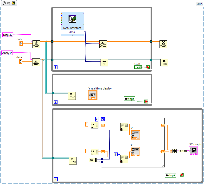
View and save the raw data DAQ simultaneously
Hello
I'm new to LabView. I'm doing a VI that continuously displays in an indicator or a gauge the value of an analog channel to a data acquisition, while at the request of the user, saving some values of this signal on a table.
I can do each of the things separately:
-display of real-time in an indicator or a gross DAQ analog gauge
-save some points of the raw analog signal DAQ
but when I try to do the two I'm not sure of the place where put assistant DAQ so it samples when it should.
The attached VI does not work properly, but you can see the 2 things I'd like to have working in parallel.Any help is greatly appreciated.
Thank you much in advance.
Hello Gabriel_Torre
You can use queues is a simple way to divide the part of acquisition from the analysis or display the part. It's the same as in the examples of producer consumer of LabVIEW.
I also recommend setting the samples/rate of factor 1/10 if the loop runs with 100ms not only every second. Now all work with time of 100ms iteration loops with this architecture.
It will be useful.
-
Connect the signal to the PRC to slot QML
Hi guys.,.
Please help me with this
I'm issuing a custom signal called imageLoaded of CPP that contains an image as a parameter. How can I connect this signal to a slot in QML and can access the image...?
Thanks in advance...

For example:
import bb.cascades 1.0 Page { id: myPage Container { layout: DockLayout {} Label { id: myLabel text: qsTr("Hello World") textStyle.base: SystemDefaults.TextStyles.BigText verticalAlignment: VerticalAlignment.Center horizontalAlignment: HorizontalAlignment.Center } Button { text: "Press me" onClicked: { console.log("Boton clicked"); cppObject.imageLoaded.connect(onImageLoaded); cppObject.executeCppFunction(); } } } function onImageLoaded(message) { console.log("enter to slot in qml"); myLabel.text = message; } } -------------------- #ifndef ApplicationUI_HPP_ #define ApplicationUI_HPP_ #includenamespace bb { namespace cascades { class Application; }} class ApplicationUI : public QObject { Q_OBJECT public: ApplicationUI(bb::cascades::Application *app); virtual ~ApplicationUI() {} Q_INVOKABLE void executeCppFunction(); signals: void imageLoaded(QString message); }; #endif #include "applicationui.hpp" #include #include #include using namespace bb::cascades; ApplicationUI::ApplicationUI(bb::cascades::Application *app) : QObject(app) { QmlDocument *qml = QmlDocument::create("asset:///main.qml").parent(this); QmlDocument::defaultDeclarativeEngine()->rootContext()->setContextProperty("cppObject", this); AbstractPane *root = qml->createRootObject (); app->setScene(root); } void ApplicationUI::executeCppFunction() { emit imageLoaded("Hello from C++ Signal"); } -
conversion of turbine flow meter
Hello
My apologies for the query, but this software is all new to me. I have a cDaq-9188 8 medium chassis containing several modules including 2 off 9401 counter modules, I run signal express version 6.0.0.
My problem is that I have 3 miniature flowmeters turbine (GEMS units FT-110 series) which give various pulse widths depending on what is the 5V square waves. I brought to the entrance of my 9401 and look of good signals so guess that's my express configuration signal which is the cause of the problem,
I connected the + ve and gnd outputs of the flowmeters Com, DIO1 + Com and DIO3, DIO0 + Com on one of my 9401 cards.
I can see the increment in the number of pulses on measurement & automation Explorer when I run test for this module Panel and watch the chefs of edge that my system can see the pulse from trains.
When configuring the express signal I need it to read in l/min, 58-575Hz corresponds to 0.5 to 5 l/min, but I can't seem to convert the pulse in l/min.
If I select DAQmx acquire > counter entry > frequency it gives me the possibility of updated the custom scale, but every time that I run it I get the error signalling DAQ assistant upward. I tried many synchronization settings with no luck. The only time where I have this power as successfully is using counter entry > County of edge, but I'm stuck on how to convert l/min as it has no function of scale (I know!)
Any help appreciated.
I think that he is referring to l/min in litres per minute, and I guess the Freq of flow are the values of this compilation on the scale.
If this is the case; Carl, it seems to me you must configure a custom scale. You can do it in the channel settings tab in the DAQmxAcquire stage. Under custom scale select Create new, and then select map scale. Min/max Freq should match your flow min/max.I have attached a few screenshots for reference.
Let us know if we are on the right track, otherwise we might need more information; FOR EXAMPLE. file seproj and a bit more info on the flow meter (type of connection, the output signal, etc.).
In addition, a brief look at the documentation on this flow meter recommends the use of a pull-up resistance. Might want to look there as well. -
Synchronization of analog and digital output with the external sample clock
Hello
First of all sorry for my English, I will try to explain what I want to do.
I want my PCIe-6321 to send two custom signals (modification sawtooths) on a mirror controller. I would also like to generate output with my card at the beginning of each tooth of saw. Everything must be synchronized with an external k-clock signal of 100 kHz. The idea is that whenever the PCI receives a trigger to external clock, it sends two analog output voltages and when he received 1024 clock ticks it will also send a pic of triggering TTL. What I do is first prepare the map and after that in a loop sending and modifing the output values of the two signals and at the same time send a digital signal Boolean in each arch, so when's done it 1024 iterations of the loop I send an event to the digital port. Attached you can see.
The problem is that I don't know how to synchronize both. Can I use the sample clock just to the analog output? I can use sample for the two outputs clock, or do I need to use the output of the meter? If don't know how to use it here.
If I do nothing else bad/wrong, I would be grateful for feedback.
Thanks in advance,
PabloI don't know how but I find the solution. I'm generating more than a positive value (as I was triggered maybe very fast the oscilloscope has been absent there). If I put the sample clock of digital output to use the sampling/ao/Dev1 clock that it doesn't, but if I put to use the same source as the OD (terminal where my external clock is connected), but the trigger to start the DO to be Dev1/ao/StartTrigger this works. I don't really know why, but it does.
Thank you for your patience and your help. I put here the final code.
-
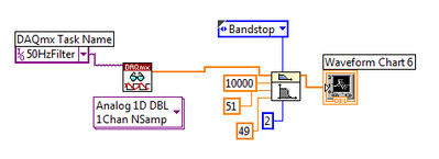
Good application of a filter of 50 Hz
Hello
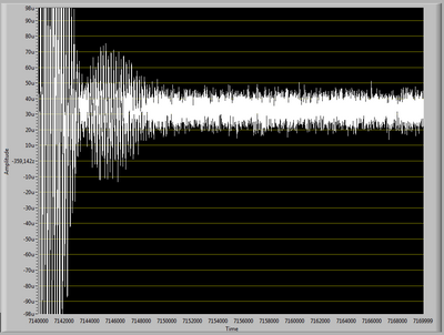
I need to apply a filter of 50 Hz to an acquisition of signals DAQ (noise for testing).
When I apply the filter, the resulting signal has enormous oscillations in the first part of the signal acquired (as see you in "Filter output.png"), after these oscillations, the signal becomes filtered as it should.
I tried to change the sampling frequency, the frequency of signal acquisition and all other settings, but I can't get rid of these oscillations.
What Miss me?
In "Diagram.png", you see the pattern of the filter.
The signal is acquired at 10 k rates and includes 30 k points.
I have some experience with Labview, but I've never used its filters.
Thanks for the help
Your image resolution is a bit low to be sure, but it seems that you have a significant lag in the data. A mismatch can lead the transient response of the filter. With a filter bandwidth, which can produce an oscillating reaction.
With your entry of noise you get very little energy in the band stop filter so it can be difficult to see the effect. When I simulate your signal with offset of the hard shoulder is almost impossible to detect. The noise in each tray is approximately 60 dB below the offset and the stopband attenuation is about the same. Without the offset the stopband is detectable (visually on a graph) about a quarter of the time. With 300000 samples, it is almost always visible with or without the offset. See the image below.
This is the spectrum of random noise with shift amplitude of 5 times and 300000 samples.
Usually interpreted restrictively the frequency response of a filter, more transient response.
Lynn
-
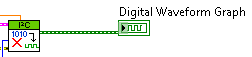
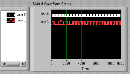
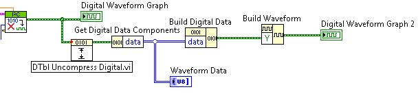
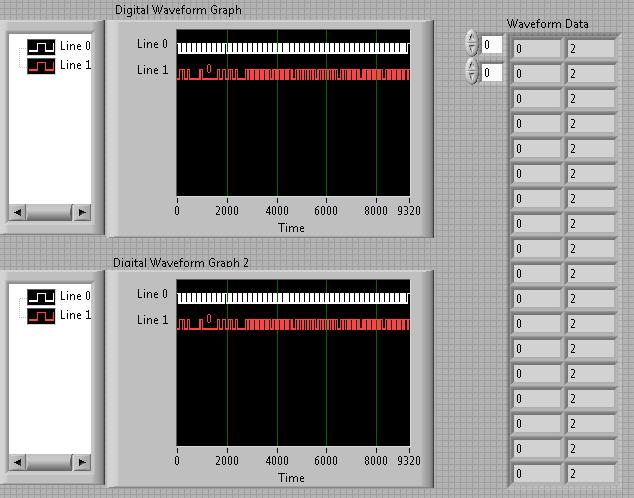
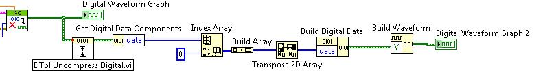
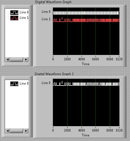
Extract a channel of a digital waveform
I use the I2C Digital Waveform reference Libarary to create a WDT which consists of two lines/channels. I was wondering how I could extract/remove a channel, the wave form and how can I add/merge signals tracks in a single WDT? I looked around for the screws, but nothing seems to work with the WDT.
Right now my WDT is like this:
How can I get these two lines in separate WDTs? And then how would I be able to merge them again? Naturally, I don't want to just remove them and merge them, but that would be an example of good practice to demonstrate.
After much trial and frustration, I found a way to do what I was looking for. It is not the most elegant, but it works!
That's how I extracted the two strings in an array and then merge to recreate the original graph:
* Note: The reason why there are 2 in the waveform data table is because my waveform contains 0 and Z instead of 0 and 1. The three States Z corresponds to the 2 digital.
I even took it a little further and extract a single line. This could be changed to extract any line and eventually merge your own custom signals:
-
Vi transitional measure displayed in the graph of the wave are moving outside the scale
With the help of a graph of a waveform to display the pressure over time. I wanted to be able to calculate the time to drop in pressure over time, so I use the vi transitional measure. I copied what was exactly in the example for the measurement of transition inside help and it is correctly determine when to transition down, but I'm having a problem with the cursors in waveform graph. I would like to see a set of greenery along the fall time start and end time of fall as pictured, I have attached the vertical sliders (capture2) as in the example. The problem is the two always begin to 3.43 (capture1) and after each sampling period they (4.34, 5.34, 6.34) increment him come right out of all of the output of transition as these numbers measure. The period of the signal that I am interested is always less than 2 seconds, so I never see the vertical sliders.
I tried replacing it by my signal daq with an sine wave signal generator and it does the same thing.
The block diagram is in the first capture
also, I would be interested to know exactly how the numbers wired to the cursor property active of the property of a waveform graph node toward real sliders on the chart. They are just automatically numbered starting at 0 from the top down?
Wayland
Hi Wayland,
The sliders are still apparent in the example VI for the transitional Measurement.vi, is because the generated signal is always set to zero. Thus, signal resets a 'new' signal for the sliders to move and therefore always on the same location a bit. The waveform graph is also configured so that it won't move or continue to show new incoming data, data sliders have moved on. So in your case, you want to click with the right button on the chart and make sure that "Ignore Time Stamp" is not checked/selected. This will make it so the graph continues with your incoming data and cursors. You can check it in the example file by removing the constant True is the generator of signals and change the mentioned time stamp option previously.
In order to view the available sliders as well as their position numbered, you can right-click in the waveform graph and select Properties. In the Properties window, there is a tab of cursors, inside this tab at the top is a drop-down menu that lists all available sliders, indexed starting with 0 at the top.
-Jake B.
-
How to get the Subvi (the virtual path is in .exe) reference in Run Time System
Hello world
The problem is how to get the reference of the Sub - VI in run time system, when the Subvi is in .exe after construction.
More details:
Top of page vi called the Subvi dynamically, so that the Subvi is always included, and the source object is the application.exe.
After the above configuration, the Sub - VI will be the application.exe. For example, the path of Subvi est...\application.exe\SubVI.vi
So, how to get the reference of the Subvi in Run Time System?
I can't do it when you use 'open reference VI' with le...\application.exe\SubVI.vi path in the run time system.
In fact, I can create a file to include the Subvi, rather than build the Subvi in application.exe, then I can get the convenintly reference. But this isn't my favourate average.
Thank you
chenyin
That is the problem. Call a Subvi dynamic means users could change, but it is also very attractive.
The dynamic call should be used in a user control, but some parade can avoid problems.
It depends on why you use dynamic calls...-online 2 main ways:
-Dynamic call are used to maintain a scalable framework for the code without acting on the executable file-online a single VI distribution managed by the administrator/developer
-Dynamic call are used to provide a collection of "external" characteristic that could be enriched by the administrator/developer. For example, you provide your customers a set of selectable custom signal filters in the executable.
In 2 cases, you are only able to assess the skills of the users to know if there is a risk of damage, if there is a change.
So to stay only master a parade might be to provide dynamic VI without a schema, but with the problem of maintenance, since no in-place editing and more attention to manage distribution.
Another way is to hide the actual distribution to user-online call dynamic VI but it without name as *.vi but others (a repellent name as system of OS name
 ) or simply without extension in order to attract not user... but that's debatable...
Another more difficult but more secure method is to create a consistency check before your routine (version, user, modified date,...)
Maybe you are looking for
-
How to move the 'new tab' button on one side of the screen to the other
A settings file had somehow end up corrupt and have reconstitute default Firefox and start over with my custom toolbars. Only problem, is that the 'New tab' button wants to ONLY go to the LEFT of the tab bar. Will not be on the side RIGHT of it as it
-
Hello. I wonder a HDD1 password. Never happened before, and I don't think I've ever put in place. Reflections on how to reset? Merry Christmas.
-
Hello. I am trying to understand how to put the string entries in a table on the right, and from top to bottom left. for example channel 1 goes to Row0Col0 (R0C0) Channel 2 goes to R0C1 chain 3 goes to R1C0 rope 4 goes to R1C1 and so on. Essentially,
-
Find the time / date of last modification of VI isn't so easy, if it's in a. BACHELOR'S DEGREE IN LAW. This is the only way I could find to do (is there a better way?):
-
Photosmart C6180 / Mac / Word - trouble printing on paper by a line
I made it every Christmas for years - print a newsletter on paper by a line purchased in-store. Always worked well, until this year. Paper this year has a darker border than in previous years. The printer offsets the output to the bottom of the page