Recording of signals DAQ
Hi all
I am a new user of Labview.
I would like to know if it is possible to build a simple VI to record a signal at a rate of sample, without specifying the number of samples to acquire priori. In other words, I would create a program that records a signal for an indefinite period, between the time wherever I start it and when I manually stop the acquisition. To stop the acquisition, I would use a stop button (maybe put everything in a whil loop?)
Could you please tell me if there is an easy way to do it with the DAQ assistant? or I have to convert and set the Subvi to achieve?
Thank you, I tried to watch if someone already posted this question, but I didn t find.
Good bye
Emanuele
Tags: NI Software
Similar Questions
-
How can I use the USRP to record a signal using its two RX ports simultaneously?
Hello.
I am trying to record a signal using two antenna cone. The reason that I need two antenna to cover the bandwidth (DC - 6 GHz). a single antenna covers DC - 300 MHz and the other covers 300 MHz to 6 GHz. so I need to use two RX port of USRP at the same time to record the signal. I have two questions:
1. is this all USRP market capable of covering this frequency range?
2. is it possible to use the two RX port at the same time to the signals of the records I described? If this is not the case, how can do?
P.S. I have two NI2920 USRPs and two USRPs N210 in my lab.
Thanks in advance for your time.
Sam.
Hi Sam,
To answer your first question, the USRPs you can reach the bandwidth you want. There is not a USRP, to my knowledge, that can reach this range in a single device.
Also note that you can only use RX convened for two different ports at the same time using LabVIEW and the pilot of the USRP. If you want to use the two lines of RX, you will need to run a session with a single line, close the session and then start a different session for your second RX line.
-
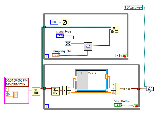
How to record a signal all on *.wav
I am trying to record a *.wav sound generated by the sinus function. I cannot record the signal of all, I can only get 1 second sound - I'm kind new to this and I have so I am struggling to get this to work.
Due to the writing to the wav format does not allow to add (I guess I might need to use another way to save information), I put next to the loop so that the file save only one loop is over. I need to find a way to get all the information in the queue, so I use Mathscript
Down while the loop has a tunnel that will display only the data of the last iteration.
What you need to do is add data, but put the waveform in a registry change so that it is available for the next iteration to be able to add more data to it.
-
recording of signals graphic permanently
Hello everyone. I have been working on recording the signals constantly. What I mean is, if I run the vi for 5 minutes, it will save the waveform from the beginning until I have stop the program (5 minutes). I managed to record the signals in jpeg format, but the problem is every time I save the image, it will overwrite the previous one. Y does it can someone help me?
-
generation of signals DAQ 6133
Can use of BNC-2110 and DAQ board 6133, I generate a sine signal and the signal sine output?
Hi WG_23,
Wondering if you can use your 6133 to generate a sinusoidal signal and connect it to the BNC-2110 to connect it to something else? The 6133 does not have the analog output capabilities, so you will need to do this, use another card.
Best,
-
acquisition of wireless signals and record the signal as text at the same time for 5 minutes
Hello
I'm wireless ECG signal and the display in waveform graph. And at the same time, I need to save it as text for 5 minutes. The problem I faced is for record of the signal, I use scripture to the extent file that saves the file as text... but everything by saving the trace speed decreases.
I'm very new to labview so please can someone me if Miss me something in it... Please help...
Why people always post photos of their screws rather than the screws themselves or at least excerpts? We can't tell from the picture what Version of LabVIEW, you use (so if we post code, you will not be able to open it), and we can not 'play' with your code and try without, ourselves, by hand, trying to recreate your diagram (sometimes very small). Please, help us help you!
This is in any case helps to familiarize yourself with the design of producer/consumer model.
- Open LabVIEW.
- Click on 'File', choose 'new '.... "(no new VI), then (in models) producer/consumer Design Pattern (data).
- Study the model and adapt it to your problem.
The producer would be anything that generates data. Once you have the data, you put on the queue and send to the consumer for the entire treatment. The idea is that the producer has an inherent calendar that he must answer, otherwise you lose data points. The consumer, on the other hand, just need to follow 'more or less' (in fact, the queue may / will develop, if the amount of data is not megabytes, so the consumer can really be quite slow, if you usually want to consumers, on average, to be at least as fast as the producer).
Bob Schor
-
We currently have a 9205 analog input module. I have several analog inputs (CSR) receive signals output of material. Recently, I discovered that if a piece of equipment is taken offline, creating an undefined signal for the data acquisition module, other chains are made and show wrong values. If I run the open path, channel signal wire to a ground, without the presence of blood, that the display returns to normal operation.
I thought about installing a switch, one side of the switch would be in line with the positive wire, connect the other end of the switch through a resistance (emptying) of the common GND on the module. Is it possible to use the labview environment to solve this problem without component externally?
What you see, it's fairly common in the multiplexed A/D converters. The ability to entrance of the accusations disconnected channels to some (unpredictable in general) and this tension can create the effects you report. The only real solution is to connect all entries not used to a low impedance source in their common mode input domain. Often a short to ground is the best thing to do. I don't know of any internal option to achieve this.
Lynn
-
Display of recorder in Signal Express
I want to display a chart of tape display a signal from slow speed (f = 0.25 to 1.0 hz) signal that represents the position that results in a resistive (1 k) position linear tranducer (IE Unimeasure LX - PA series). This view must move left as new signals are acquired, rather than updating a display both as a field of application; IE more recent signal is on the right side, and there are N seconds are displayed on the left edge.
I'm a THE Signal Express 'newbie '. I have the signal from the NI USB 6211 correctly and displaying as a scope, but may not know how to change the view of what I want.
Any ideas or suggestions?
You must pass your signal through a step amplitude and levels:
- Add step > analysis > temporal measures > Amplitudes and levels.
- Go to Set Up settings and deselect RMS, leaving only the DC value controlled.
- From there just drag and drop this signal (the newly created DC signal) in the graph
- Right-click on the graph, and then select the Update Mode
- You should now have the opportunity to see in band, scope, or sweeping graphic.
Hope that's what you're looking for!
-
VI not emitting the Signal DAQ
I'm working on a project that requires two different waveforms to two separate channels. It also includes a trigger for a computer that has a camera connected to it. I received a VI that someone had already used for a similar project and had to learn LabVIEW 'language' for the first time. Unfortunately it does not appear to be out of any signal through data acquisition channels. I've combed on VI is not looking for something to strangely wrong without result; everything looks like it should work, but it simply does not work. I used a simple signal generator provided with LabVIEW to generate a sinusoidal signal, and he did show my two-channel oscilloscope. I also tested all the hardware to ensure that the VI was at fault. Is could someone please help me understand this problem? It would be much appreciated.
-
record two signals - sinus 20 kHz in 1 minute - rate of 400 samples
Hello world
Is it posible to save two sinusoidal signals in one minute with samples of rates. How I can achavied this. Its a lot of samples. When I tried, programe out with error message saying that "attempted to read samples that are no longer available. Required sample was previously available, but it has since been crushed. "When I increase the number of samples to read there are of the same (outgoing). When I read all the samples it reads to me that some elements ferst save a minute and rest of the signal are declares. In one minute programe will be saved 12000000 samples and I guess for a signal due to 400 kHz rate. To save, I use tdms blocks (open, writing, relatives).
Whot I'm doing wrong? Please help.
Marek
There are a few things I can suggest:
1 take a look at the following article:
Why should I get error-200279 of my DAQmx Read VI or the property node?
2. you must have an architecture of producer/consumer when you're reading in these high sampling frequencies and trying to save all the data in a file. My suspicion is that it may cause the problem that you are facing. You can access the model for the architecture of producer/consumer navingating the file-> New... in LabVIEW. Take a look and let us know if you have any other questions.
-
-
What NI DAQ device or system can receive signals nanovolts?
We have an analog sensor here that its production gives us nanovolts control signal. I was wondering is there any device NI DAQ, you could introduce me so that I can take these steps for the Labview? (signal to noise ratio is low) It would be great if you also offer me an Osciloscope code or software in Labview that get the signal of the DAQ hardware and I can play with, or record the signal as a real Osclloscope because I couldn't find a good in the examples. If this question is not linked here please provide a link for me to remove this item and it ask for more in the forume somewehere. Thank you
nV is not much
 so some requirements more are needed:
need resolution?
need for precision?
bandwidth of the signal?
the source impedance (or current bias data acquisition acceptable entry?)
Value of Absolut or changes in the amplitude? (important for the specification of the drift)
I would go with a preamplifier or ask Keithley
 NI sorry
A good source of information to measure really tiny values is the "low level measurements Handbook" of keithley...
Sorry, no link to it... These % $§ ' engine % of research do not provide direct plus links

-
Signal (PAL 60) record with the Qosmio G40 Line In (Capture) Option
I'm in Australia - and I have a lot of NTSC video tapes I want to MPEG...
These bands play very well on all the TVs/LCD TV in the House.
Qosmio G40 seems to have problems with PAL 60 signal that sends my VHS player...
My VHS/DVD from Toshiba drive is to convert NTSC to PAL 60 signal - as this VHS player bought in Australia - this seems to be the Australian standard bought a VHS/DVD player.
There is no option on the VHS player to the NTSC signal... I tried another VHS player - and it gives me the same output PAL 60, this player also could leave the NTSC signal...
So I wonder if the Qosmio G40 is able to record the signal PAL 60 - maybe I'm missing a setting somewhere...
I use Ulead movie maker software, which is supplied with the machine... but I don't see any options on the support PAL 60...
Maybe the TV card installed in the machine does not support PAL 60 - I can't find any info about this...Maybe I need to use a software of different capture which will support PAL 60 options...
Or maybe I just buy a VHS of America drive, and qosmio q40 will capture the NTSC image very well... (I already have a few products from 110V at home)Any thoughts?
Hello
I'm not sure if this is possible, but you can check the BIOS settings, if there is an option that would allows you to change settings of NTCS/PAL.
Check it out
-
Hello
I'm new with LabVIEW. I need it for my project. I use the interface USB (k8055) card. I know it's not good to use it, but I have to use.
I don't have counter on this forum. I need to record a signal and transferee it to a file where I can look at the time at which the pulse is generated.
I have a sensor this sensor pulse send (k8055) USB interface card. I want to measure the time between each pulse and the duration of each pulse.
I have of course a timer. I found the timer on the forum, but I does not work with what I'm building.
As I mention, I'm new in LabVIEW. I use LabVIEW 2010
Hello Nadjil,
Thanks for the additional information!
Below some comments from me:
(1) in the context of acquisition VI now read you the data and save them in a file (in collaboration with "time information")
Time you get currently comes from the VI of number of cycles and won't give you information on when the DLL was called.
This can give you indeed information on when the acquisition is made, but it will never quite add up.
You might be able to make it a little more accurate with both the call to the function 'ReadAllAnalog' of the dll and the call of the VI of number of cycles in the same flat Structure of the sequence. This way you could maybe get a little more specific information when the DLL is called.However, it still won't be exactly at the time the effective acquisition is made on the Board from velleman.
(2) when you talk about "the counter" what should I say exactly?
Are you talking about the data produced by the number of cycles VI?
Essentially the information you can get from this are the relative difference between different calls to the function 'ReadAllAnalog' of the dll.
Simply subtract the first 'number of cycles' of the entire procedure ones.(3) it is still is not clear to me why you need to reopen the connection to your device in each iteration of your loop.
(4) it is also not not clear to me why put you your waiting until the next multiple ms VI in a loop with 1 iteration for?
The reason for adding in this loop is also not clear to me. It's not be used anywhere, so it can be deleted.
-
Digital synchro recording signal using PFI0/PFI1
Hello
I try to sync data between an instrument NOR cDAQ-9188XT acquisition and a 3rd party.
The instrument of 3rd party kicks out a digital synchronization signal which consists of a short pulse whenever it samples followed by a series of pulses coding a 32-bit integer (see image - signal synchronization for 3 bags). This integer is the serial number recorded with each packet of data. Samples of instrument to a pace of 2 kHz, so the pulse + whole occurs every 0.5 ms and by my rough calculation, each bit of the integer lasts 5 µs.
The cDAQ-9188XT will record a series of analog channels by using LabVIEW, and I wish to record this signal to synchronize with the analog channels, so I can sync the two sets of data in post processing. There is no spare slots in the cDAQ so I can't use a digital I/o module and I believe that the frequency of sampling of my analog channels will be too weak to pick up the signal from sync.
The cDAQ-9188XT has two BNC connectors on the frame that correspond to lines PFI0/PFI1, I would like to know if it is possible to use a PFI line to record this signal of sync?
See you soon.
Pat.
Think about it once again, if you're happy with the post-processing of the data, then you can get in with the straightforward acquisition code (maybe start with an example of the semi buffering period ). This will give you a picture of the down time of the signal that then you need to decode in the 32-bit number.
Best regards
Maybe you are looking for
-
Can anyone recommend a good replacement battery for Toshiba C660/C660D? Ours does not have its charge for a very long time now and we want to replace but a bit overwhelmed by the choice online - a good market will work or that is false economy? Thank
-
How auto search for fotos duplicate within an event
When I down load pictures from different sources on my iMac, there are opportunities to double, but the pictures do not appear next to each other, as the dates of these photos are not the same; so in a file large, they could be anywhere. I don't know
-
completely remove the OLD version of QUICKTIME on my computer
How can I remove the OLD Version of Quicktime? Even if he tells me its no LONGER there.
-
How to make a smaller picture when it sends to a Web site... He always says that he is too big and I have to reduce its size. Help, please
-
Have tried to uninstall TrayApp.msi I went to Control Panel - uninstall, nothing happening Pleez Help