cutting data to draw
Hello, I would ask how to divide the data to plot. According to the attachment, I want to split each data flow of n ° 1, stream n ° 2,..., n ° 1 of pressure, pressure No.2... to plot individually in the graph. I tried to use set, but it came out only two lines for maxi and pressure. Could you please help?
Thank you
Try the attached vi
Tags: NI Software
Similar Questions
-
How to cut data in pieces, have been collected by DAQ assistant?
like the image below, the data were won by a random number generator in a loop for a vector that contains 10 points each time
scrip MATLAB to process will be. now, I want to get the data by the DAQ assistant
but I can't my goal, can someone help me?
You could say the DAQ Assistant, to return only the number of samples to be processed. I'm still lost as to what exactly you are looking for.
-
Hello
I have a dream.
I want a program to plot the data I put in the table, and then I can save the table and plot.
the attachment is a trial. It is not very good, but he says the concept.
Thank you
Cynitha
-
SQL Loader (how to cut data header)
Hello
[oracle 11g]
I got the following text file:
Now I am interested in the column TBL and ATR and follwing rawdatamod; DD.MM.YYYY; HH:MM:SS; aligned src; "ptv "; "15.04.2012"; "10:47:49" chs; "ISO8859-1" ver; "V1.0" ifv; "V1.0" dve; "V1.0" fft; "LIO" tbl; MENGE_FGR atr; BASIS_VERSION; FGR_NR; FGR_TEXT frm; num[9.0]; num[5.0]; char[40] rec; 122; 8; "VVZ" rec; 123; 18; "VHZ" rec; 124; 13; "VTZ"
Can you see a way to automatically create the MENGE_FR table with columns BASIS_VERSION. FGR_NR; FGR_TEST and column types num, num, char and insert raw data below?
PS:OK, it's mysql... .so I need to convert this sql first. So, you should see num as number.
THX in advance Thorsten
Published by: Thorsten on 16.05.2013 07:30
Published by: Thorsten on 16.05.2013 07:32There are various ways you could do this. I demonstrated one of the methods below. I created a table with two columns, and then use SQL * Loader to load the data from the text file in these two columns. Skip header lines is optional. You can also use a portal instead, if the text file is located on your server, not your client. I then used some PL/SQL to create and run 'create table' and 'insert '. It's just a startup code. You will need to make changes to manage other types of data, and others who were not in the example you provided, but it should give you the general idea.
SCOTT@orcl_11gR2> host type text_file.dat mod; DD.MM.YYYY; HH:MM:SS; aligned src; "ptv "; "15.04.2012"; "10:47:49" chs; "ISO8859-1" ver; "V1.0" ifv; "V1.0" dve; "V1.0" fft; "LIO" tbl; MENGE_FGR atr; BASIS_VERSION; FGR_NR; FGR_TEXT frm; num[9.0]; num[5.0]; char[40] rec; 122; 8; "VVZ" rec; 123; 18; "VHZ" rec; 124; 13; "VTZ" SCOTT@orcl_11gR2> host type test.ctl options(skip=7) load data infile text_file.dat into table tbl (col1 terminated by ';', col2 terminated by x'0a') SCOTT@orcl_11gR2> create table tbl 2 (col1 varchar2(4), 3 col2 varchar2(60)) 4 / Table created. SCOTT@orcl_11gR2> host sqlldr scott/tiger control=test.ctl log=test.log SQL*Loader: Release 11.2.0.1.0 - Production on Thu May 16 13:44:24 2013 Copyright (c) 1982, 2009, Oracle and/or its affiliates. All rights reserved. Commit point reached - logical record count 6 SCOTT@orcl_11gR2> select * from tbl 2 / COL1 COL2 ---- ------------------------------------------------------------ tbl MENGE_FGR atr BASIS_VERSION; FGR_NR; FGR_TEXT frm num[9.0]; num[5.0]; char[40] rec 122; 8; "VVZ" rec 123; 18; "VHZ" rec 124; 13; "VTZ" 6 rows selected. SCOTT@orcl_11gR2> declare 2 v_tab varchar2(30); 3 v_atr varchar2(32767); 4 v_frm varchar2(32767); 5 v_sql varchar2(32767); 6 v_cols number; 7 v_next varchar2(32767); 8 begin 9 select col2 into v_tab from tbl where col1 = 'tbl'; 10 select col2 || ';' into v_atr from tbl where col1 = 'atr'; 11 select col2 || ';' into v_frm from tbl where col1 = 'frm'; 12 v_sql := 'CREATE TABLE ' || v_tab || ' ('; 13 select regexp_count (col2, ';') + 1 into v_cols from tbl where col1 = 'atr'; 14 for i in 1 .. v_cols loop 15 v_sql := v_sql || substr (v_atr, 1, instr (v_atr, ';') - 1) || ' '; 16 v_next := substr (v_frm, 1, instr (v_frm, ';') - 1); 17 v_next := replace (v_next, '[', '('); 18 v_next := replace (v_next, ']', ')'); 19 v_next := replace (v_next, '.', ','); 20 v_next := replace (v_next, 'num', 'number'); 21 v_next := replace (v_next, 'char', 'varchar2'); 22 v_sql := v_sql || v_next || ','; 23 v_atr := substr (v_atr, instr (v_atr, ';') + 1); 24 v_frm := substr (v_frm, instr (v_frm, ';') + 1); 25 end loop; 26 v_sql := rtrim (v_sql, ',') || ')'; 27 dbms_output.put_line (v_sql); 28 execute immediate v_sql; 29 for r in (select col2 from tbl where col1 = 'rec') loop 30 v_sql := 'INSERT INTO ' || v_tab || ' VALUES ('''; 31 v_sql := v_sql || replace (replace (r.col2, ';', ''','''), '"', ''); 32 v_sql := v_sql || ''')'; 33 dbms_output.put_line (v_sql); 34 execute immediate v_sql; 35 end loop; 36 end; 37 / CREATE TABLE MENGE_FGR ( BASIS_VERSION number(9,0), FGR_NR number(5,0), FGR_TEXT varchar2(40)) INSERT INTO MENGE_FGR VALUES (' 122',' 8',' VVZ') INSERT INTO MENGE_FGR VALUES (' 123',' 18',' VHZ') INSERT INTO MENGE_FGR VALUES (' 124',' 13',' VTZ') PL/SQL procedure successfully completed. SCOTT@orcl_11gR2> describe menge_fgr Name Null? Type ----------------------------------------- -------- ---------------------------- BASIS_VERSION NUMBER(9) FGR_NR NUMBER(5) FGR_TEXT VARCHAR2(40) SCOTT@orcl_11gR2> select * from menge_fgr 2 / BASIS_VERSION FGR_NR FGR_TEXT ------------- ---------- ---------------------------------------- 122 8 VVZ 123 18 VHZ 124 13 VTZ 3 rows selected. -
Hello
In my project, I use card PCI 6221.
I can able to get data from a graphic design, DAQ card and save OK file.
But I need to manipulate dynamic data before drawing the graph and backup in the file.
I entered sensor, input voltage I need to edit as 10mv = 1unit. before writing to the file.
How I can do this, any ideas please.
Kind regards
Hari
Hi David
I found the solution, thanks.
Kind regards
Hari
-
Hello.
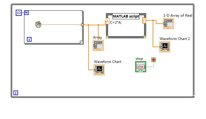
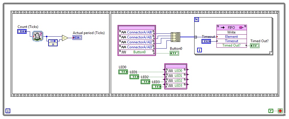
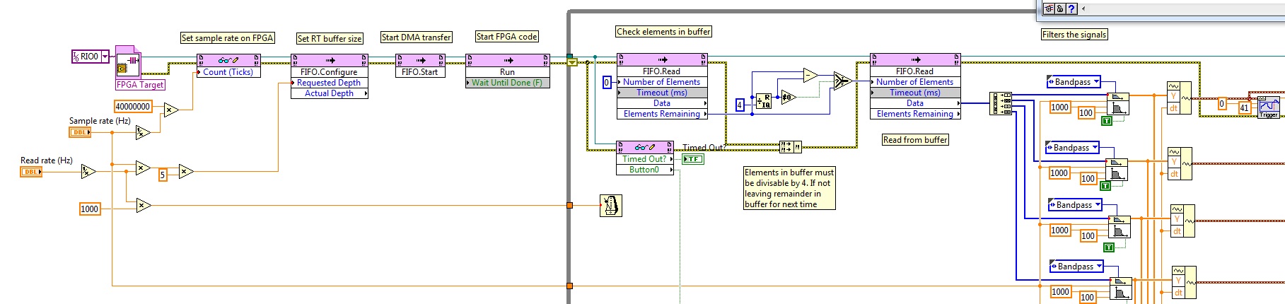
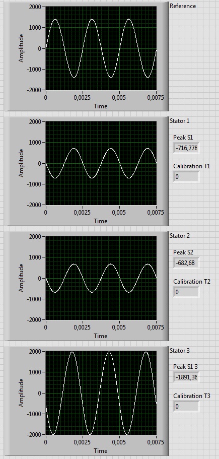
I am new to LabVIEW and myRIO. I'm designing an acquisition and treatment system for the sync. I have 4 four signals 400 Hz sinusoidal, acquired by four 4 analog inputs being implemented on the FPGA, write the data to a FIFO. On the side of RT, I read these data and draw. The problem I have is the plot of switching, and I think it's a switching between channels of data. I tried to delay the writing process, the initialization of an array and forcing the correct order of writing, increase in the size of buffer, and neither solve them the problem. What could be the problem? The correct order is: Stator 3-> reference, reference-> 1 stator, Stator 1-> 2 Stator and Stator 2-> 3 stator
Thanks for your help.
BJoa.
Solved!
In the configuration pop-up the 'open FPGA VI reference', uncheck the "Run the FPGA VI".
-
move the data points on the waveform display
Hello
No idea why the waveform display to my VI has shift the data points? The third tab of the screen does not display this problem. I took a video of what happens to better illustrate what I'm talking about and attached my VI to identify the problem.
I am currently a sample of data from a DAQmx and storing in a queue until data backup button. Everything works well, but the problem is the display of actual data, which, although sense points, it shows move in a small area around where they are drawn in the first place. It happens even when I erase the visible data and restart the collection of data, as shown in the video.
Thanks for any help you may be able to provide.
Guy
The amount of data you draw? If you draw a lot more datapoints that there are pixels on the x-axis of the graph, you can get peaks that appear to move because of graphic interpolation LabVIEW has to do.
Mike...
-
How can I cut & paste in the address bar?
How to cut & paste? It's been too long, can not think! Help!
Hello
Select what you want to copy or cut with the cursor of the mouse - and then Ctrl + C to copy or Ctrl + X to cut - move the cursor of mouse where you want - then Ctrl + V to paste
Here's a good tutorial on cut, copy, and paste
http://www.bleepingcomputer.com/tutorials/tutorial95.html
Copy text
What happens if you work on a word processing document and you must take the text that is in another document and add it to the current document. You can manually type the information found in the original document in the new document, but which could take quite a long time. Fortunately for us, the operating systems give us the ability to copy text from one document to another document called copy. When you copy data highlighted, this data is stored on the Clipboard until you are ready to paste this data into another program
To copy something, you first highlight the text you want to copy using one of the methods described above. Then when you highlight text you want to copy, you can copy it to the Clipboard in one of three ways:
- When the text is highlighted you can press the Control key and the C button the same to copy the data.
- Right-click on the files or highlight text and clicking on copy.
- If there is an edition menu you can click Edit and then click copy.
Once you use one of these methods a duplicate of the highlighted text will be placed in the Clipboard, allowing you to paste it into another document or application.
Cutting text
Cup is very similar to copy they have both put the item highlighted in the Clipboard to paste future. The difference is that you have when you cut the text selected, it will remove, or cut, the text of the original location and place it in the Clipboard. So it is important to be careful when you use this command, because it is possible to lose data if you mistakenly cut the data in the document and then save the file.
To cut text you must first highlight the text or data you want to cut by using one of the methods described above. Then when you highlight text you want to cut, you can cut it to the Clipboard in one of three ways:
- When the text is highlighted you press the Control key and the X button in the same cut data.
- Right click on the highlighted text and clicking on cut.
- If there is an Edit menu, you can click change , and then click cut.
Once you use one of the following methods, a copy of the highlighted text will be placed in the Clipboard and highlighted data will be deleted from the document. It is important to note that the text just disappears a document if the document is editable. For example, you can not cut text from a web page or a set of documents read-only because it is not editable.
Now that you know how to copy and cut data of a document and put it on the Clipboard, you must learn how to retrieve these data and place them in your document. Once the data has been copied or cut from a document, you can then paste it into another document, or the same document by retrieving this information to the Clipboard using the Paste command.
Simply move your cursor to the location where you want the data to be pasted into your document and then choose one of the methods to paste the data.
- With the cursor at the location where you want the data to be pasted press on the button control and the V key in even to paste the data.
- Right-click on the document and clicking on dough.
- If there is an edition menu you can click Edit and then click Paste.
After you use one of the commands above the data contained in the clip Panel will now pasted into the document.
-
Predefined VectorLayer do not return data
Hello world
I'm completely stumped. I'm trying to restore a theme preset using the HTML5 API of Oracle cards, and it is simply not appear as it is not all the data. I have a table defined as such, which traces the outline of a store manager:
STORE_FLOOR_DATA
--------------------------------------------
NUMBER OF STOREID,
NUMBER OF FLOOR,
FUNCTION VARCHAR2 (50 BYTE),
GEOM SDO_GEOMETRY
Samples (note that I am using a 0-1.0 X / coordinate system, 0,0 in the bottom left of the blueprint and 1.1 top right.) I use-1 as an SRID:
STOREID FLOOR FEATURE GEOM
1 1 UP TO 5 SDO_GEOMETRY (2003, NULL, NULL, SDO_ELEM_INFO_ARRAY (1,1003,3), SDO_ORDINATE_ARRAY (0.25,0.25,0.5,0.5))
I've added an entry in USER_SDO_GEOM_METADATA and created a spatial index on geom
I've implemented my data source, in MapViewer and set the config as well:
< name map_data_source = "nosql".
jdbc_host = "localhost".
jdbc_sid = "orcl".
jdbc_port = "1521".
jdbc_user = "nosqluser".
jdbc_password = "ZoXpqdRt1hfmn/fISARJxgX2DXOQDn6r".
jdbc_mode = 'thin '.
number_of_mappers = '3 '.
allow_jdbc_theme_based_foi = 'true '.
Editable = "false".
/ >
< mds_config >
< name data_source = "nosql" >
< allow_predefined_themes > true < / allow_predefined_themes >
< allow_dynamic_themes > true < / allow_dynamic_themes >
allow <>
< subject > STORE_FLOOR_THEME < / theme >
< / allow >
< / data_source >
< name data_source = "nosql" >
< allow_predefined_themes > true < / allow_predefined_themes >
< allow_dynamic_themes > true < / allow_dynamic_themes >
< / data_source >
< / mds_config >
I then used mapbuilder to create the STORE_FLOOR_THEME theme, using the XML below:
<? XML version = "1.0" standalone = "yes"? >
< styling_rules >
< hidden_info >
< column field = "STOREID" name = "STOREID" / >
< column field = 'FLOOR' name = 'FLOOR' / >
< column field = "FEATURE" name = "FEATURE" / >
< / hidden_info >
< rule >
< has style = "L.STORE_LINE" > < / feature > ""
< / rule >
< / styling_rules >
The geometry column is, of course, the GEOM column.
When previewing the theme in mapbuilder, it seems, all the rectangles are drawn as expected.
I wrote a narrative view, and I've used the below some code to add the topic of the current map:
var storeplan = new OM.layer.VectorLayer ("storeplan",
{
def:
{
type: OM.layer.VectorLayer.TYPE_PREDEFINED,.
dataSource: "nosql"
Theme: "store_floor_theme."
URL: baseURL
loadOnDemand: false
}
});
Map1.addLayer (storeplan);
I dragged on the STOREID, FLOOR and FEATURE columns in the analysis criteria.
My problem is that the theme is not rendered in the view. When I look at firebug at the request of mapviewer, I see the following:
{"type": "FeatureCollection",}
"CollectionName": "store_floor_theme",
"srs":-1,.
'geodesics': false,
"attr_names": [],.
"attr_types": [],.
"Features":]
]}
Notice how, no data is retrieved in the theme (attr_names, attr_types, and features are all empty)? That is why it is not rendered, I guess. I have no active filter, and if I add a table view I see all rows returned as expected. For some reason, the theme itself thinks there is no geometry data to draw.
Can someone explain to me why this is happening? I would be very grateful.
Kind regards
Richard
Hi Renan,
Sorry for the delay in response, I've been away.
I managed to solve the problem in the end, it seems that he did not use-1 as an SRID, at the time when I changed it to something else like 8307, suddenly it worked. Since I am not a map of the world or making of distance calculations at the present time, it is not a major problem if viewing thinks that my clients are somewhere off the West coast of Africa. I need to understand what SRID in use thereafter however.
-
The tool brush Flash CC suddenly stops drawing when the step is small
When you use the Brush tool, I have a problem that will be the race I paint abrupty cut at one point on the screen (about halfway to the bottom of the screen, it does not concern the position of the canvas or the coordinates). This seems to happen when I have the scene size set to a smaller size (64 x 64 pixels for example). I was able to reproduce the same behavior on several files and a Windows 8.1 machine and a Windows 7 machine, both using the updated version of Flash CC. Both machines are double monitor, I'm not sure if that plays a factor.
To reproduce:
1. create a new FLA in Flash CC and set the size of the scene to 64 x 64 pixels.
2. use the Brush tool and try to shoot from the top to the bottom of the screen (zoom level and position on the canvas is okay, as long as your cursor is going to the top of your screen to the bottom of your screen).
3. the race cuts abruptly Mid-drawing at some point on the screen, about half way down. You can continue to draw and move to the top, and it reappears when it crosses the barrier again.
This does not occur if the size of the scene has something bigger (640 x 480, for example). This also happens in Flash CS5 or CS6 and have noticed only happens in Flash CC.
What is happening with the mouse to draw and also happened when I tested it on another PC with an attached Wacom tablet.
Is what is happening to the other institutions, and is at - it a fix for this problem? (aside, always using a size big stage)
Hi all
I want to just inform you that this issue has been resolved internally and even will be available to you as part of the next version of Flash CC.
Thank you!
Mohan
-
A query with the weeks/months/quarters without filling data
During recovery of monthly data from any data source, experts how CF (which I am not one) creates results for the time intervals where there is no results? I.E. event data to draw per month, how can I show that there can be no activity for a given month? Thanks in advance.There is a way to make more efficient approach to dempster.
Step 1: run your query from the database. (1 queries)
Step 2 - create a cold fusion query to get all years-months in the range of dates of interest (2 requests)
Step 3 - make a query of queries for years-monthly query 2 that are not in the application 1. (3 requests)
Step 4: make a query of queries that questions 1 and 3 trade unions. -
Hello
I can't find an example where I can create a custom class plot. I have to be able to line the plot of color based on the value of Y and make it look like a smooth gradient. Ideally, I would like to change the size of the line as well. This would allow me to "draw" the 3 variables using a 2D graph. I started (VB.Net):
Imports NationalInstruments.UI
Public Class clCustomPlot
Inherits from point cloud
Public Sub New()
MyBase.New)
End Sub
Protected / Sub OnBeforeDraw(ByVal sender As Object, ByVal e As NationalInstruments.UI.BeforeDrawXYPlotEventArgs)
End SubEnd Class
But VS tells me that:
Void of MeasStudioGraphLineColour error 'OnBeforeDraw' cannot be declared 'overrides' because it does not replace a sub in a base class.
Thanks for your help,Nicolas
I got it to work! For all those who are interested, here's a VB.Net custom dispersion diagram that will show you how/color along the line of control.
Imports NationalInstruments.UI
Imports System.Drawing
Imports System.Drawing.Drawing2D
Public Class clCustomScatterPlot
Inherits from point cloud
Private dblMin As Double
Private dblMax As Double
Private colMinColour As System.Drawing.Color
Private colMaxColour As System.Drawing.Color
Public Sub New (ByVal MinValue As Double, ByVal MaxValue As Double _)
ByVal MinValueColour As System.Drawing.Color, ByVal MaxValueColour As System.Drawing.Color)
MyBase.New)
"no check is performed for the fact that MinValue<>
dblMin = MinValue
dblMax = MaxValue
colMinColour = MinValueColour
colMaxColour = MaxValueColour
End Sub
Protected override void OnBeforeDraw (ByVal e As BeforeDrawXYPlotEventArgs)
"Clip data, browse the data cut, map and draw."
Dim intrigues as XYPlot = e.Plot
Var clippedXData() As Double = Nothing
Var clippedYData() As Double = Nothing
parcel of land. ClipDataPoints (clippedXData, clippedYData)
For i As Integer = 0 To clippedXData.Length - 2
Protected x 1 Double = clippedXData (i)
Protected x 2 = Double clippedXData (i + 1)
Var y1 As Double = clippedYData (i)
Var y2 As Double = clippedYData (i + 1)
Dim point1 As PointF = plot. MapDataPoint (e.Bounds, x 1, y1)
Dim point2 As PointF = plot. MapDataPoint (e.Bounds, x 2, y2)
Var pen As Pen = New Pen (ValueToColour (y2))
Dim g As Graphics = e.Graphics
g.DrawLines (pen, new PointF() {point1, point2})
Next
e.Cancel = True
End Sub
Private Function ValueToColour(ByVal value As Double) As Color
If value<= dblmin="" then="" return="">
If value > = dblMax then return colMaxColour
Pctg As Double = (value - dblMin) / (dblMax - dblMin)
Dim a, r, g, b As Integer
a = CInt (CInt (colMinColour.A) + pctg * (CInt (colMaxColour.A) - CInt (colMinColour.A)))
r = CInt (CInt (colMinColour.R) + pctg * (CInt (colMaxColour.R) - CInt (colMinColour.R)))
g = CInt (CInt (colMinColour.G) + pctg * (CInt (colMaxColour.G) - CInt (colMinColour.G)))
b = CInt (CInt (colMinColour.B) + pctg * (CInt (colMaxColour.B) - CInt (colMinColour.B)))
r = Math.Max (0, r): r = Math.Min (255, r)
g = Math.Max (0, g): g = Math.Min (255, g)
b = Math.Max (0, b): b = Math.Min (255, b)
Return System.Drawing.Color.FromArgb (a, r, g, b).
Var col As Color = System.Drawing.Color.FromArgb (a, r, g, b).
Return col
End Function
End Class
-
How to read a file that contains a matrix!
Hi all
I have a file that I saved from matlab using this command: SAVE filename X - ascii-double - legs.
but I don't know how to read and extract its data to draw the graph of the intensity.
Any help please.
Best regards
Nams
-
I am trying to use the CWgraph to display data from the serial com port but there is no chance. I used the mschart1 but that comes with VB6 and everything works very well, because they need to acquire 3 hours of testing, I would prefer to use Measurement studio.
I'm going to fix my code, Hope you can help me guys.
PS: I'm using VB6 with M-studio v 2.1
kmous,
Yes, zoom out on the 2d chart, you want to
the value of the TrackMode to TrackZoomRectXYWithUndo so you can cancel the zoom.
It's the best way to essentially to zoom out. To obtain your code, you can
to add a control to your timer code to check the valid data before
draw you it then you are not drawing the leading 0 before getting your
data. Together perhaps a sort of boolean flag as soon as you receive data
is not 0 (rather than throw all 0s, so you can always trace 0 s
later if you get them) -
I did the following steps:
Created a report model (page).
Each page has 4 cards
1 X, Y, Z plot (the accelerometer data)
2 FFT transforms (1).
3 and 4 are the same for the next channel, and there are 5 total channels.
Looking dialog box Definition of curve and the axis, it shows the type, color, y axis (which are all Y1), X (white) and Y-way (my data).
What I try to do with my script, it's that it can scroll through all the data and draw using the specified model.
Each channel is labeled "N X (filtered)" where N is 1-5, and there is a X, Y and Z. The FFT is labeled: 'N X (filtered) FFT' with all of the channels.
Hope it makes sense.
Thank you.
Hi Worldtraveller,
I sent the solution I created directly to you, Yes.
Brad Turpin
Tiara Product Support Engineer
National Instruments
Maybe you are looking for
-
Lenove z510 battery - cannot start the laptop
Hi all I bought a lenovo z510 7 months ago. It was working fine. Suddenly, battery does not charge while the AC adapter is connected. Then, she fell to zero, and now I can't open. It recharges even now. I tried to uninstall the ACIP, the energy Manag
-
RLC, AC single frequency analysis results do not match hands calculated results.
On a single RLC monofrequency simulation analysis AC, the amplitudes resulting are off by a factor of 10. Phase angle values are all correct and correspond to the calculated values. On another example developed in a text book, same results. What I am
-
HP 15-af024AU APU Quad Core A8: How do I start bluetooth on HP-15af024AU
I bought the laptop mentioned above by looking at its specifications. It includes no bluetooth services. However, there are no button or any other provision to start despite the display shows the icon of bluetooth and its equipment after searching fo
-
positioning of tabs in the tab controller
I would slave master loops using one of the design templates. I want to put all the slave code to the controller tab that would allow users to move from one page to another. Please see attached file. I got 10 pages but when I click on a tab from one
-
Problems with Outlook Express (address book, mail open, etc.)
Hi, I have a strange problem with my outlook express. The program opens ok, it synchronize the e-mail with the servers and so on. If you click on an email in the upper part of the window you can see the content below.Now, this is my problem, I can no