DAQmx Timing of the meter and analog readings
Hey all,.
Quick update. I hung a second function generator to a PFI port on my DAQ and did a sample clock for each channel (IA and CI) type, then did two clocks to the same port. Bingo, I have the same number of samples in each column, and the data looks correct.
If the lesson learned: you can use the same external clock, but not the same clock for different channel types. Tip.
-Lyric
Tags: NI Software
Similar Questions
-
How meter and analog value FIFO synchorize
I use a card NI 6123.
Anyone knows how to put 6 analog values and the value of the counter in FIFO with the same rate: 4 k.
Thus, every second, there should be 6 * 4 k analog values and 4 k in FIFO counter value.
The problem is:
1. the counter is a numeric value, so I can't put a sampling on it. So how can I put the value of the counter in the FIFO every second of 1/4000
2. how to sync analog channels and channel meter.
-------------------------
DAQmxErrChk (DAQmxCreateTask("",&datHandler));
DAQmxErrChk (DAQmxCreateAIVoltageChan(datHandler,"Dev1/ai0:5","",DAQmx_Val_Cfg_Default,-5.0,5.0,DAQmx_Val_Volts,NULL));)
DAQmxErrChk (DAQmxCfgSampClkTiming(datHandler,"",4000,DAQmx_Val_Rising,DAQmx_Val_ContSamps,4000));
DAQmxErrChk (DAQmxCreateTask("",&ctrHandler));
DAQmxErrChk (DAQmxCreateCICountEdgesChan(ctrHandler,"Dev1/ctr0","",DAQmx_Val_Rising,0,DAQmx_Val_ExtControlled));
DAQmxErrChk (DAQmxStartTask (datHandler));
DAQmxErrChk (DAQmxStartTask (ctrHandler));
-----------------------------------
Thank you
It is possible to apply for a meter in the buffer. (this is actually preferred). Simply specify a sampling and source clock. Given that you want the meter to "lock" data from the meter to the same rate as the sample analog clock to simply specify this sample clock as the sample for the meter clock.
An example of event in the buffer (life-long) count can be found here by using an external clock (your HAVE sample digital Instruments\NI-DAQ\Examples\MStudioVC2005\Counter\Count Events\CountDigEventsBuffContinuous_ExtClk clock):...\National)
Check out this example and I think he should get you operational.
-
Why do I get signals ghosts with the meter?
Hi, I am able period using the NI 9401 on a cDAQ9174 chassis. I have a sensor whose output is 50mV LO and HI 4500mV, and this is easily measured with a scope and a DMM. Furthermore, the scope shows very clean transition, no noise near the 2, 5V TTL threshold. The probe monitors pattern reflecting on a spinning wheel. Measures the time of the order of less than 0.3 seconds, but, curiously, the measurement period seems to be good for a few cycles, and then suddenly these values close to ZERO are observed. (Excel data show these values literally '0'.) What is c? Where are these unwanted readings from?
Also, see the code that I use to record data from the period, and a typical example of the data plotted in Excel. One thing I'm confused about is the timer in the WHILE loop. How the meter may return a value that is smaller than the function parameter WAITING in the WHILE loop? The WAIT function is set to 100ms, but the meter will return to values far less than 50ms.
Is there a way to remove these values in the software? For example, can I just throw any value less than 0.050 seconds? This kind of fix would be perfect for our application; It's a little gross, but she would get me to the next step in our project.
I really appreciate your comments! This photointerrupter is supposed to have the advantage of being a camera and free of noise in the environment, up to now, the only noise in our environment is the small DC motor spin our wheel on our lab bench... not a harsh environment at all.
Dave
Hi Dave,.
That's what I think is happening here. In the configuration of the measurement of a meter task period DAQmx, the source of the signal is connected to the door of the meter and the internal time base is used as a source. When the input signal is HI at the entrance to the Terminal, a count is saved for each rising edge of the timbase to the source of the Terminal. When the signal of door to LO County is drawn from the register in the buffer and legumes subsequent source are ignored until the door is HI again.
Now assume that the signal of your door is swinging very quickly prior to staying at the State HI or LO. Whenever a HI LO oscillation occurred, a count would be drawn from the register of the meter. If this rise and fall of the door happened quickly enough, it is quite possible that very few or none of the timebase impulses were actually counted to the source terminal, thus recording a very low double value in a buffer of the computer. When these sets of values has been extracted from the buffer and written into the worksheet, accuracy of scripture to the worksheet VI may have been set to the default 3 decimal, so write "0" s to the file.
The speed of the swing may be the order of 10 to 100 ns, fast enough at your fingertips, do not register. The quote that I copied the help file describes the behavior with the digital filter enabled. When you apply the digital filter, a county is not from the register unless the signal of the door remains HI for a fixed minimum amount of time. With the filter, the period 0 counts are not sent to the buffer because the door is not HI for the minimum period of time.
Brian
-
(Vista) Is there a PRACTICE way to switch between speakers and analog headset?
(Vista) Is there a PRACTICE way to switch between speakers and analog headset? Must I ALWAYS return the default setting, depending on which audio output device I want to use?
We have recently installed Music Maker 16. Before that, we never had a need for headphones and a microphone. Now, in trying to use the headphone and microphone - and THEN switch back to speakers - we discover a problem. Apparently, the only way to do it is to change the audio output device by default EVERY time.
The dispute with this cannot be more of this. My son records a beat and singing (with headphone and microphone), and then, play through speakers (so we can all hear), we need to change the default settings. And back... There must be a better way!
Any help would be greatly appreciated. Please talk layman jargon; I'm not a COMPUTER guru. Thank you!!!
Hi AnnieElle,
You will need to switch between the speakers and the analog device and special value to use as the default device. There is no way to set the device to be used at the same time. You can follow the steps below to switch between the speaker and analog device.
1. right click on the speaker icon in the taskbar.
2. click on the playback device.
3. Select speakers or analog device.
4. right-click on it and click on set as default device.
Hope the above information helps.
Thank you and best regards,
Srinivas R
Microsoft technical support.
Visit our Microsoft answers feedback Forum and let us know what you think.
-
Using the DAQ USB-6009 meter and an analog input voltage at the same time.
Hello
Currently, I'm reading the two channels of voltage with the USB-6009. It happens that one of the channels is the output of a digital coder, and it would be much easier to use it directly to the PFIO entry that is defined as a counter. The problem I am facing right now, it's that I can't use the DAQ Assistant to use the analog voltage to a channel and the digital channel counter at the same time. Once I put the DAQ Assistant to read the input from analogue voltage, I won't be able to add analog inputs. And as I put the DAQ Assistant to use the PFIO as a counter, I can add more entries to read analog voltage is.
I wonder if it is possible to solve this problem using the lower level data blocks? Another solution would be to read two channels in analog input voltage and that the use of Matlab to process data resulting from it, since I was not able to do the counting to work simultaneously with the acquisition in Labview to impulses.
Hope you guys can help out me.
Thanks in advance.
Using a simple wizard of DAQ is incorrect. You need one to acquire analog inputs and one for the meter.
-
Send the meter digital outputs while gaining analog data
Hi all
I'm looking to acquire analog inputs on several channels and send simple TTL pulses at different times during the acquisition using a Board from UBB-6221. Delays at the outset of the acquisition and the release of life should be handles by a control on the front panel. I got it work using the software timing and an inexpensive board before, but the program needs to be more specific than that (so timing equipment). I write the program using DAQmx and LabView 8.2, but if necessary, I have 8.5 available as well. I know well the General LabView program, but'm not comftorable with DAQmx, which I suppose I should use (I only really used the Wizard). If there is an example of this somewhere, or if someone has done in the past, I would really appreciate the help!
Thank you!
Hi LVhelpME,
There are a number of different ways to do it, but I created a quick method that makes a digital waveform with the number of samples and asking rate and then allows you to specify at what time you want to insert a "trigger" (which basically means that he will place a high in at this point in the waveform). I did this using only 3 functions and a loop that traverses according to triggers and how you want to insert. You can use a similar method or just make this code in a Subvi, which will create your digital data correlated according to the total number of samples, sampling frequency, and the specified time you want the triggers occurs to. I have attached the VI below for LabVIEW 8.0 and later versions, as well as a screenshot showing what the digital waveform will look like based on what values are entered for moments of relaxation. In the screenshot below, you'll see that there are 2000 total samples that are emitted at a frequency of 100 Hz. Thus, the total waveform will last for 20 seconds, and the trip times are listed as 5, 10 and 15 seconds.

The following image shows a zoom in view of relaxation that is created during the second 5 brand, which will last for the sampling period of 0.01 seconds (100 Hz sample clock period).

Hope this helps,
-
input analog trigger on the door of the meter to measure the frequency of generation
Hello
I want to measure a frequency on the analog input, but it doesn't seem to work.
I'm trying to work with DAQmx with the use of the ansi c standard.
The first step, I've done was acquiring information on the analog input. With the use of a simulated device, it shows a sine wave on the entry.
My next step is to generate a trigger for the meter signal, but this doesn't seem to work.
I don't see how it is possible to connect the trigger on the entrance to the analog meter.
For the creation of the analog input and relaxation, I use the following code:
DAQmxErrChk (DAQmxCreateTask("",&taskHandle));
DAQmxErrChk (DAQmxCreateAIVoltageChan(taskHandle,"Dev1/ai0","",DAQmx_Val_Cfg_Default,-3.0,3.0,DAQmx_Val_Volts,NULL));
DAQmxErrChk (DAQmxCfgSampClkTiming(taskHandle,"",10000.0,DAQmx_Val_Rising,DAQmx_Val_FiniteSamps,1000));DAQmxErrChk (DAQmxCfgAnlgEdgeStartTrig (taskHandle, "Dev1/ai0 ', DAQmx_Val_RisingSlope, 0 '"));
For the creation of the meter, I use the following code:
DAQmxErrChk (DAQmxCreateCIFreqChan (taskHandle1, "Dev1/ctr1", "", 1 January 2000, DAQmx_Val_Hz, DAQmx_Val_Rising, DAQmx_Val_LowFreq1Ctr, 1, 4, ""
 );)
);)I hope someone could give me a hint.
I also tried the examples that come with DAQmx but well I know this are only examples to counter with the help of the digital inputs.
Thanks in advance.
Hello
You must use the exit event of comparison at the entrance of the meter. Change this property after the configuration string function.
DAQmxSetChanAttribute (taskHandle1, "", DAQmx_CI_Freq_Term, Dev1/AnalogComparisonEvent);
Kind regards
Bottom
-
Problem when the PWM signal combinning and analog signal TOGETHER!
Hello everyone,
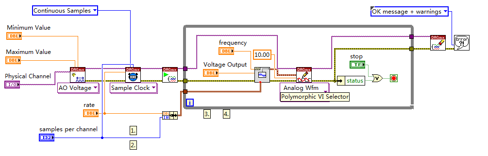
first I DAQmx 6212, and I need to run the water pump small (9V - 16V) that should be driven by a PWM signal; I also have a motor (5V - 13V) for a water supply which must be controlled by an analog signal and it has built in a force feedback potentiometer, I logged onto this potentiometer correction + 5V the DAQmx and used the output voltage of the third extremety as a value to diagnose to know the position of the engine.
My VI shows:
1 is a normal meter production to create my PWMout signal.
2 is an analog input, I use it as a PWMin to the LabVIEW to diagnose what is happenning in my pump water through the cycle and frequency.
3 is an entry of the third extremety of the analog potentiometer.
4 is an analog output that I used as power supply of the motor valve and I used an AC/DC amplifier for aplify signal the DAQmx and the motor road, between the two (3. 4.) I made a comeback with a few calculations, I had a P-controller to know the real position of the engine valve.
My problem:
When setting to 1. and 2. in the same VI only, I get an own PWM output with no problem.
also with 3. and 4. in the same VI only i can control the motor valve without any problem.
but when I put all these 4 set found in the attached VI, I have a problem as the engine valve turn continuously without stopping even if I change the position of the valve between 0 and 100%, I should mention that I see a PWM normal outside a signal on my oscilloscope, another thing to delete one of (1 or 2) and run the engine valve VI works fine without any problems.
so this my problem, if you can think of any solution please let me know.
Thanks in advance for your help.
Kind regards
Caliente
Here's your VI, slightly modified so the two analog inputs belong to the same task. This if only for purposes of illustration, I him have not tested. You will still need to do some debugging.
While changing your VI, I noticed another potential problem with your original configuration. You have configured the two tasks of AI for the same frequency, but read you 10000 samples of one of them and only 100 samples from the other (and throw it most of it). Data acquisition data are buffered, and if you read as fast as you acquire, the buffer fills eventually. If you read 10,000 samples of a channel, and the other channel acquires at the same rate, then when you read from the second channel you will get old stale data or an error full buffer.
-
How to sync analog & meter and two usb devices
Hello
What I want to do is synchronize the analog inputs and an entry on a device (USB-6009) meter and then synchronize this device to a different USB USB-9211.
I had a quick glance at the Web site and there are a few articles to the knowledge base on how to do these operations independantely (IE synch and synchronization channel) but I'm not sure how to bring it all together. My concern is that the USB-6009 case has only a single meter (which double as the PFI?) and it is generally used for the signal synchronization on the slave device? Used to say that I won't be able to use the meter to measure input? The USB-9211 a there a PFI connection?
Any suggestion would be appreciated.
See you soon!
Hi David,
If you want to synchronize and always stay USB, you will need to look at the chassis USB 4 9174. With this, you can get a digital I/o module, for example the 9401, to interface with chassis backplane and synchronize the frame on another device like the 6009. Another plus, it could ask, is that the bottom of basket 9174 meters integrated into the chassis, which have more capabilities than the meter 6009 and are accessible via the same DIO module that you use for synchronization. This seems to be the best route to go because of the capabilities that you are looking for.
-
Questions about the synchronization between output and analog input
Hi all
I now have a simple task which head a signal voltage (from PXI ao0) on a circuit and then your comments a voltage at the terminals of a component, for example, that one of the resistors in the circuit, through ai0 on PXI. So in this case, the synchronization between analog input and analog output must be made to avoid error of phase shift.
I tried to build my VI by learning this example: https://decibel.ni.com/content/docs/DOC-3882
However I have a few questions.
1. I noticed that there is a merged error fed the "start task" sub VI for the analog output. What is the point of fusion to mistake?
2. I enclose my VI (also shown below) for the output voltage. I put my writing of DAQmx Subvi in the while loop so that I can change the voltage while the VI is running.
However, in the example, the author has been reading outside of the loop and before even the start task. What difference will it make?
3. I have also attached my synchronized VI. I always put the wavegeneration and the DAQmxwrite in the loop. A bulging guard error saying about samples is not available and needs to a higher sampling rate or a longer wait time. What causes this?
I appreciate that these problems can be solved. Thanks to you all.
(1) first you need start the task of acquiring, he'll wait for trigger here. And then you start the build task that provides this trigger. If acquisition could trigger and never start.
(3) you must first write something in the buffer (writing DAQmx), then only you can generate it (Daqmx Start).
Check Cont Gen tension Wfm - Int Clk - no Regeneration.vi in the help-> examples for example.
-
Simultaneous use of flex pitch and the "timing" on the same region?
Is it possible to edit a region in 10 with the two flex pitch logic and timing? When I toggle between modes, I get a message that informs me that pitch adjustments will be suspended. If I put the pitch of the notes to something way off - to check it out - it seems that as soon as I switch to flex pitch in calendar mode, pitch adjustments are ignored. Is it possible to have both at the same time? Workaround is bounce calendar settings in place then the correct pitch. Is this the best way? The only way? Any information would be appreciated. Thank you. -John
IF you use flexible hours first then flex pitch your flexible hourly landmarks remain intact. In pitch flex mode you can select to the end of a note and drag to the right or left and upwards or downwards. So you can bend the pitch and flexible at the same time, but only when there is an event of note.
-
Terca M4: How to activate the external ports, DVI and analog?
Please can someone please tell how to activate the two external ports. I would use two DVI and analog to the office. Currently if you activate a second screen machine sets up the flat screen and the other the DVI external display. Is this in any way about this?
See you soon
Hi Matthew
As far as I know you can connect an external monitor or a TFT. For this you can use the VGA (15-pin) port or DVI - D video, supported by PortReplicator III (PA3314E).
Sorry, but I don't understand why you need the two holes at the same time. How many external screens that you want to use? Sorry if I'm missing something but perhaps you can explain your wishes more precisely.
Good bye
-
How about using labview vi of the filter and multiply vi to replace the analog filter and amplifier
Hi all
I use a data acquisition system to acquire a weak signal, it seems to a voltage amplifier and low-pass filter before the acquisition of data. I was wondering, if I use low-pass of the labview vi of the filter and multiply vi to process the signal picked up by DAQ, can I get the same effect as the analog low-pass filter and amp?
Thank you!
No!
1. any system of sampled data must be band including prior to sampling in order to avoid aliasing. It is impossible to remove aliasing after collection.
2. the resolution of the DAQ system will be so low that you'll very 'fat' scanning and you will lose a large part of the information in your signal.
Sorry, but you need to amplify and filter in the material before the data acquisition device for best results.
Lynn
-
Implement and control 'meter' in S7 - 300 by the OPC and LabVIEW
Hello world
I use a S7-300 PLC and OPC Server for my projects. I have a problem: S7 - 300 has a meter module which digital signal of County. I only can implemented using SIMATIC STEP 7. Can I set up the meter module using only the server OPC and LabVIEW
does anyone have a solution or an idea for my problem?
could you please help me...
Thank you
Hi Echion,
NOR-DAQ (MX) is used only for material OR: no you can not use it.
To program the controller you must use the right programming environment. For Siemens S7, you need to use Simatic (or perhaps some other 3rd party software supporting IEC61131). Point.
The OPC server is used only for the exchange of data. This is no interface programming!
-
Integration of material NI_DAQ and NOR-DAQmx software on the same system PCI-DIO-96
Hello
We have a great system that is developed in VB and uses the traditional inherited NOR-DAQ system. The system controls the controller PCI-DIO-96. We would like to upgrade to some parts of the system to NOR-DAQmx and use VB.Net and we know that you can install both systems together on the same computer.
We have a few questions:
(1) once the legacy of NOR-traditional DAQ OR DAQmx software can be integrated in the same system. Some parts of the system will always use the VB and the other parties will use VB.Net.
(2) if the answer to the first question is Yes. Are there hardware or software limitations? Is there a recommended way to integration?
(3) are there articles based on the knowledge about it?
Thanks Jeremiah
There are a number of limitations to the use of NOR-DAQmx and NOR-DAQ traditional at the same time. First of all, only one of the drivers can access the device at a time. To switch between the drivers, I recommend that you read this knowledge base Article: that I can use OR-DAQ traditional (old) and NOR-DAQmx simultaneously? You will need to use the equivalent functions of VB .NET to switch between the pilots.
In addition, the system should use Windows XP or an earlier version.
Maybe you are looking for
-
I would like to permanently delete some items that I bought on itunes
There is a very long time I tried to buy a few episodes of a tv show and some audio books. I downloaded audio books, but has never managed to download the TV show. I don't want more either. whenever I try to sync my phone with itunes on my laptop, it
-
How can I get all my Icloud photos on my computer?
I have thousands of pictures on Icloud I have to put on my computer so that I can print, but I'm not sure how to get them on my computer. I downloaded icloud on my computer but it added new pictures of her. It has all my old photos...
-
constant outside the friendrequests of males (I suspect fraudulent)
I want to know how and where foreigners can see my Skype profile or account to constantly send a friend request I suspect fraudulent behavior since most males, known as generals or people of such nature, I think not they are legitimate, my settings a
-
Dumping file hex in the pic microcontroller via ICD3
I am able to empty the hex files in pic microcontroller using command line utilities provided with MPLAB. But whenever I have to empty a hex file, I need to go to the location of use ICD3 programmer (in the MPLAB directory) and paste the hex file to
-
HP pavilion 15-e092sa install win 7
Hello I've had this laptop for a while now, and I still can't get used to win 8 or 8.1 for the aaagghhh case. I want to buy Windows 7 and install it, but by browsing the tinternet I can't find drivers that work with 15-e092sa if I installed it. It mu