DAQmx Timing
Hi all
I have this suite solution VI resulting LabVIEW example for continuous digital data output. The question is about the system clock - if you select a value of low sample rate (say, 1 s/s), the rate seems to be much higher. The light on my BNC2120 is dimmed on the whole; which indicates a rapid change between the Low and High?
How can I change the closed VI actually write a sample per second? I use the PXI-6132 card.
Thanks in advance.
If you use 100 kHz clock, then do a waveform high for 100,000 samples and then low to 100,000 samples. You will then have a table of 200 000 samples to write.
Tags: NI Software
Similar Questions
-
Hello
Looking for the online help on a task daqmx timed.
I am trying to run 2 fans using tasks of acquiring data MX for some time. The sequence is the following:
1. start the FAN 1 and run for 2 minutes.
2 after the 2 minutes time, STOP FAN 1 and FAN 2.
3. operate the FAN 2 for 3 minutes.
I need to help, incorporating a timer in the task.
I would really appreciate if the community would throw an overview of this. (Maybe a quick picture of the code?)
Thank you
RP.
-
Several DAQmx Timing screws - all seems to work, just a question
I wrote a Labview program to interface with a cDAQ-9188 and everything seems to work very well. I used the DAQ Assistant to make the features of basic level and then convert them into DAQmx code and which went very well.
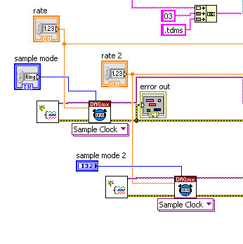
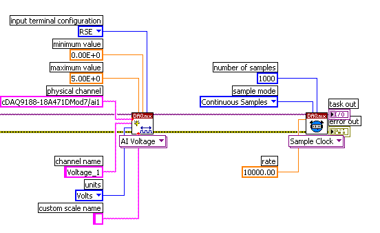
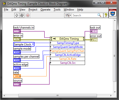
When I created the code DAQmx a timing clock didn't appeared not so I added a vi DAQmx sample Timing (sample clock) in order to have control over the rates. I tested the software, including changing my recording speeds, and everything worked as expected. (see image).
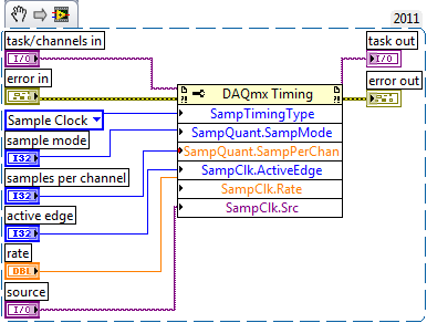
When I looked in the SubVi DAQmx I created, I saw that a synchronization clock was actually there (see image). It contained cable to it (sample, rate, samples per channel mode) but this content does not seem to affect what I have in the main VI. Heck, I don't even samples per channel wired on the main VI, I plugged it into my DAQmx Read in my all loop!
If the Timing of the main VI is predominant in the Subvi calendar? Should I take the full schedule of the Subvi?
Once again, everything seems to work as expected. I have more work to put into this and I fear that it will cause headaches in the future. Also, I want to be more informed about what I do!
I have attached the VI and SubVIs as this seems to be the Protocol. They are under construction!

Thanks for the help.
If you open the VI schedule you will find that it contains just the DAQmx definition properties:
Calling it the second time only replaces what you have done previously. It would eliminate a redundancy to just call him once (you could delete the calendar from your Subvi or pass the parameter in the Subvi to configure it) but it isn't a problem to call it twice.
Best regards
-
Strange DAQmx Timing delay home error loop
I have a digital dashboard introduced in a timed loop counter. Everything works fine until I have stop the loop and stop the task of data acquisition. Once I restart the loop that it fails with 'resource is reserved. My code is attached.
Thank you
I think the problem is that when you set up a timed loop to use DAQmx task as its source of the time, the timed loop is automatically set to start the task at the start of the loop. Here, you never seem to stop the task of counter before restarting the timed loop. For the second time that you run the loop timed, it tries to restart the task of Counter and sees that a task is already running with this resource (from the first timed loop run).
If you use the function of the task to stop the task of counter after the timed loop, you should be able to restart things.
-
DAQmx Timing of the meter and analog readings
Hey all,.
Quick update. I hung a second function generator to a PFI port on my DAQ and did a sample clock for each channel (IA and CI) type, then did two clocks to the same port. Bingo, I have the same number of samples in each column, and the data looks correct.
If the lesson learned: you can use the same external clock, but not the same clock for different channel types. Tip.
-Lyric
-
Hi all!
I have a question about the calendar with the DAQmxbase functions. I have the task to save data with a sampling frequency static (it will be greater than 100 000 points per second in theory) and I need to display a writing data to the file in real time. So my idea was to put the sample clock to whatever the desired sampling frequency (lets say 100 000 at the moment) and I would have a loop of standard state machine (just a while loop with shift registers and a case statement inside) to collect data and write to the file then to decimate the data to display to the user. Each of these iterations, the amount of data read would be one-tenth of the sampling rate so I thought I could count just iterations until I arrived at the sampling frequency * 10, which would be the total number of hours. Unfortunately, after the execution of this program for a desired 20 minutes to 50,000 points per second, I noticed that the iterations had invariably longer over time, but it was so small that I didn't notice when I tried for 3 to 5 minutes. Is that what this has to do with the decimation of data slow down the program because we need to reallocate the array every time or it has to do with my way of thinking wrong in the way of our recordings of tension time?
Information
-LabVIEW 2014
DAQmxbase - package used
-System MAC OS X
- NI USB-6211
Needs
-L' sample rate > 100 000 points per second
-record for a specific amount of seconds by the user
-written in the file and displays the user data
Problems
-While the iterations of the loop are run 0.1 of a second making the program more continue to record the tension longer than expected
Please, if you do not understand or I forget important information please let me know!
1 State Machine is NOT good architecture here. You must keep this look DAQ run fast enough to track data in data acquisition. Use rather a producer/consumer. The idea here is that you have parallel loops that make the data recording and processing of data and let the DAQ loop to just read the data that it is.
2. in windows calendar is not reliable. Do not trust it.
3 use the configure DAQmx Timing (assuming that there is no in the DAQmx Base) do DAQmx data stream into your PDM file. It's one thing less worries and it is much more effective would you be able to do.
4. If you follow my advice in (1), then you should read a certain number of points for each iteration of the loop. Let's say 10kS. Therefore, each iteration of the loop will be 100ms. But for your decimation, you take all 10 samples. There is a simple decimate 1 D table that you can use to make it easier on yourself.
-
Error-200524 occurred at .vi:2 DAQmx Write (analog 1-d NChan DBL 1Samp)
I'm trying to generate a signal to usb-6009 of simulated signal.
However, he keep poping errors:
Error-200524 occurred at .vi:2 DAQmx Write (analog 1-d NChan DBL 1Samp) if I choose "1 sample on request" in mx data acquisition.
If I have chaged to "continuous sample", the error has become
Error-200077 during the property Node DAQmx Timing (arg) 1 DAQmx Timing (sample clock) .vi:3-> 1.vi:Instance:0:1-> Untitled 1 Untitled. VI
Can someone could take care of my problem?
Very appreciate
The limitations of the analog output of your device is documented in the manual and has been considered on several occasions. Because it supports at the time of the application, you can only pass a single value to a moment, not a waveform. The timing is only the software and you can not generate a signal without a lot of jitter and the max frequency will be by the spec.
-
a node property to return the configuration of the task a DAQmx
Tasks in this project are preconfigured in MAX, but once the operator needed to enter and change the sampling frequency, that I would like to add a routine to start to check the sampling rate of the configured tasks. I know that using a DAQmx property node can return task names and channel names, but what I could use is a property node to return the sampling frequency of the task. A knowledge of a way to do this?
If you place a property on the block schema node, connect it to your task control. Right-click on the property node, and then select the DAQmx Timing (class select DAQmx-> DAQmx Timing). Then select the sample-Rate property > clock.
-
Why a task of analog input shows shape of different signal than DAQmx Test Panel?
I have a DAQ SMU-6363multifunction material. I need to view CHA and CHB with an encoder. I had connected CHA ai4 + and CHB ai5 + thanks to a SCC-68 in differential mode box. I provide + 5V from the power supply of the PXI-4110 of the encoder. I have connected ai4 - and ai5 - to the MASS of the power of the encoder on SCC-68 screw terminals.
PROBLEM: When I create a TASK acquires of ai4 and ai5 at the same time, the shape of the signal is distorted. See picture attached.
If I look at signals with an outer scope touch screw terminals, the signals have the form correct and without distortion.
Also, if I look at one of the signals with Test DAQmx Panel I n MAX, I know the form correct and without distortion.
I have also included a snippet of my code.
Is something wrong with my SMU-6363?
Only one channel at a time on the 6363 acquisition would give you the sampling frequency of 2 MHz. However, the rate of the overall sample is only specced to 1 MHz, due to the time constraints of the used multiplexer compaction.
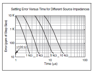
What you see, it's probably due to ghosting, and it should happen in the test panels as well if you measure two channels at once. This happens if you don't leave enough time for the channels to settle after multiplexing. Here is a table of specifications of 6363 which indicates the time of settling for various source impedances:
In your first picture as an attachment, the error is about 500 mV on a stage of 5V. It would be 10 per cent, or 100 000 ppm.
The same image, I see that you set a frequency 200 kHz 2 channels sample clock. Thus, the sum of 400 kHz to 2.5 would allow us to decide between channels.
Looking at the chart above, (2.5 US, 100 ppm k) is off the chart, but if extrapolate you the curves we could wait for your source impedance is somewhere around 5-10 kohm. Is this correct? If you have a link to the datasheet for your encoder, I'd be happy to take a look.
You do not see the error at 40 kHz 2 channels because it allows up to 12.5 US (1/80 kHz) for the settlement - in fact, DAQmx as default 11 us maximum convert the 6363 period when you buy slow enough to allow the time of settling in this case would be so 11 US. If you had to, you can reduce the clock rate to convert manually via a property node DAQmx Timing if 11 that we by default does not allow enough time for your application. The maximum conversion period which by default is DAQmx is the inverse of the maximum speed of the overall sample (in your case, 1 / 1 MHz = 1 US) + 10 to the United States.
Article ghost link above has some suggestions to eliminate ghosting, the most likely solution for you would be to implement a voltage follower if you need to acquire higher rates than allows the regulation of the multiplexer in view of your signal source. The voltage follower allows to considerably reduce the impedance as seen at the entrance of the DAQ card.
Best regards
-
USB-2009, Task.Timing.ConfigureSampleClock fails
I work with a USB-2009 and want to write a byte array to the digital output using DigitalSingleChannelWriter.WriteMultiSamplePort. The following c# code illustrates what I'm trying to do. An error occurs when ' task. Timing.ConfigureSampleClock' is performed and the message below.
I read the documentation of NOR-DAQmx .NET. It does not specify what are the classes and/or function should not be called on the USB-2009 so I don't know whether or not the "ConfigureSampleClock" can even be used in this situation.
Can someone tell me or provide me with sample code that shows how a byte array can be sent to the digital output on the USB-2009? If the USB-2009 is not designed for that, then that would also be helpful to know. If your example is only for analog output, then I think it would be just as good. I am able to output a successful single byte, one at a time, on the line of digital output... but not a byte array.
Thank you
Ian
===============================
Code example
Note the following object instances:
"Simulator" simulates a wave with an amplitude of 255 square
"deviceID" manages the the string ID of the USB-2009
int x = - 1;
Byte [] waveData = new Byte [Simulator. Count];
{foreach (Double sample in the Simulator)
waveData [++ x] = Convert.ToByte (sample);
}using (task task = new task ("myTask")) {}
task. () DOChannels.CreateChannel
deviceID + "/ port0."
"myPort."
ChannelLineGrouping.OneChannelForAllLines
);task. Timing.SampleTimingType = SampleTimingType.OnDemand;
task. () Timing.ConfigureSampleClock
String.Empty,
samplingRate,
SampleClockActiveEdge.Rising,
SampleQuantityMode.FiniteSamples,
Simulator. County
);
task. Control (TaskAction.Verify);DigitalSingleChannelWriter writer = new DigitalSingleChannelWriter (task. Stream);
writer. WriteMultiSamplePort (waveData, true);} / / using (task task = new Task()) {}
===============================
Error message generated by executing the line "task. Timing.ConfigureSampleClock':
NationalInstruments.DAQmx.DaqException: The requested value is not supported for this property value.
Property: NationalInstruments.DAQmx.Timing.SampleTimingType
You asked: NationalInstruments.DAQmx.SampleTimingType.SampleClock
You can select: NationalInstruments.DAQmx.SampleTimingType.OnDemandTask name: myTask
State code:-200077
to nNIMSSAIL100.StatusObserverT<><>
 otNetApi > >. CheckWithName (StatusObserverT<><>otNetApi > *, tCaseInsensitiveBasicString
\,_STL::allocator \,nNIDMXS100::tLocaleConsideringWideStringComparitor\,nNIDMXS100::tLocaleConsideringWideStringCaseForcer>* pName) at NationalInstruments.DAQmx.Timing.set_SampleTimingType (SampleTimingType value)
at NationalInstruments.DAQmx.Timing.ConfigureSampleClock (String signalSource, Double rate, SampleClockActiveEdge activeEdge, SampleQuantityMode sampleMode, Int32 samplesPerChannel)
at Test.MainForm.testNINetLibrary_Click (Object sender, EventArgs e) in C:\Users\XXXXXl\Documents\Visual Studio\Projects\Digital IO - test\MainForm.cs:line 197
Hello Ian,
The error you see is because you try to cinfigure a sample clock that is not actually present. The USB-6009 case is completely timed software (which means that the values are updated based on your loop rates and the speed at which your computer can change). It seems that you are calling the right to property, the error message seems a bit misleading. We can consider the issue to see if it's something that needs to be corrected. Normally, the timed SW just requests do not configure a sample clock. Here's an exit code only once, so do not hesitate to repeat just update you need.
int main (void)
{
error int = 0;
TaskHandle taskHandle = 0;
data uInt32 = 0xffffffff;
char errBuff [2048] = {'\0'};
Int32 wrote;/*********************************************/
DAQmx Configure Code
/*********************************************/
DAQmxErrChk (DAQmxCreateTask("",&taskHandle));
DAQmxErrChk (DAQmxCreateDOChan (taskHandle, "port0/Dev1", "", DAQmx_Val_ChanForAllLines));/*********************************************/
Starting code DAQmx
/*********************************************/
DAQmxErrChk (DAQmxStartTask (taskHandle));/*********************************************/
DAQmx write code
/*********************************************/
DAQmxErrChk (DAQmxWriteDigitalU32(taskHandle,1,1,10.0,DAQmx_Val_GroupByChannel,&data,&written,));Error:
If (DAQmxFailed (error))
DAQmxGetExtendedErrorInfo (errBuff, 2048);
If (taskHandle! = 0) {}
/*********************************************/
Stop DAQmx code
/*********************************************/
DAQmxStopTask (taskHandle);
DAQmxClearTask (taskHandle);
}
If (DAQmxFailed (error))
printf ("error DAQmx: %s\n",errBuff); ")
printf ("end of the program, press the Enter key to quit\n");
GetChar ();
return 0;
} -
DAQmx: (almost) synchronous Continuous Acquisition / how to trigger Council transfer buffer?
Hi :-) :-) :-)
We have an NI USB 6289 acquisition card. I would like to continuously acquire an entry of 'almost' analog synchronously. How synchronous 'almost', I mean that when a Read DAQmx is executed (anytime), I would be able to recover all the data present on the PC AND buffer all data present on the stamp on the card at the time of the read command.
In order to test the behavior of the DAQmx Read, I used the following DAQmx vi (for a life-long real I would need a loop structure, but it's just a theoretical experiment):
DAQmx create task
DAQmx Create Channel (polymorphic instance HAVE voltage)
DAQmx Timing (instance polymorphic sample clock, Mode sample set on samples continues, the rate set at 1000)
DAQmx Start Trigger (polymorphic instance Start / None)
DAQmx beginning
Here the program waits n seconds (variable), then
DAQmx Read (instance polymorphic analog Wfm/1Chan N Samp, number of samples per channel-1).
Buffer FIFO of Council seems to be large 8192 samples.
If the time between the beginning of DAQmx and DAQmx Read is less than the approximately 8.2 seconds, DAQmx Read recover whatever it is, if it is more than 8.2 seconds, DAQmx Read retrieves 8192 samples. I expect this behavior: fills up the buffer Board it triggers the transfer of all data in the PC buffer and DAQmx Read reads the buffer of PC, it cannot recover data after the transfer has taken place.
What should I do in order to force the transfer of data from the buffer of (even if not full) Board to the PC at the time of the DAQmx Read buffer while the timing is in CONTINUOUS mode? I would like to be able to recover all the data from the buffer of PC and the Board of Directors in order to have all the most recent data and without having to put in place an acquisition of finite samples and a circular buffer of software.
I tried the DAQmx channel property node Analog Input/Properties Advanced options/General / Data transfer and data/memory transfer mechanism and set set of e/s, but it doesn't work or the DAQmx channel property node Analog Input/Properties Advanced options/General / Data Transfer and status of application for data/memory and set it to Onboard memory Custom threshold but I could not access the property of Custom threshold (this is not there!).
I'm sure there's an easy way to do this but I did not understand as yet...
Thank you!!! LucaQ
I am inclined to agree with Ravens Fan. However, assuming that you must use the USB DAQ for your application, a better way to implement your code would be as follows:
-
Error-200609 occurred in the DAQmx write: selected buffer too small
Hello, I write a few VI simple test that I will build finally to call external analogue output VI. I started with a very simple program to produce samples finished using the clock on board with DAQmx Timing.VI. When I run the program, I almost immediately get an error. The error message is below.
Error-200609 occurred at writing DAQmx (Analog DBL 1Chan 1Samp) .vi:1
Possible reasons:
Generation cannot be started because the size of the selected buffer is too small.
Increase the size of the buffer.
Contradictory property
Property: Output.BufSize
Corresponding value: 1
Minimum supported value: 2Task name: _unnamedTask<1C>
I used the VI DAQmx before in similar applications and never encountered this error. In addition, I read the link below which DAQmx Timing.VI should automatically generate the buffer. Any ideas what could be the cause?
Data sheet:
Windows 7
LabVIEW 2012
PCIe-6353 as DAQ card
Here is a picture of my diagram and the VI is attached
.
Oops. Just realized my very stupid mistake: I forgot to add the VI of task start. I did and it works as expected.
-
Greetings,
I have two questions probably related. A question is that I am trying to use an interval to retrieve data of a sample continuous DAQ cards (I have tested this on a 6361 and also a 16XE-10). When I run the code, I specify a sample rate and a sampling interval to choose the number of samples to receive. The number of samples to read door should how long takes it from the read operation, however, the time required to complete this operation is never my specified sampling interval which doesn't make much sense to me. In addition, the dt for my data is always 0, as if she doesn't really know the sampling frequency. This is probably a stupid mistake where I do not forget a set, but maybe someone can see my error and report to me. Thanks for the help.
Attached is an example vi that must show the question.
The sample default calendar type is "On Demand" and it doesn't seem like you have changed it. Why not just call DAQmx Timing.vi to set the clock sample settings? It encapsulates the property nodes that configure the sample clock calendar:
Best regards
-
How to control the number of cycles in the shape of triangle
Hello
I'm quite new Labview programming and find a hard time to code a simple program. If anyone can help me find a way to control the no. cycles of a triangle pattern.ie, if a key is pressed the code should send an individual right. wave form when it is in place the button should switch to its original state. I enclose the code that I've used to working on. The material used are NI 6013 and NI6723, as well as two BNC-2110 as input and output.
Thank you best regards &,.
George
Hello
first of all, if you want to have an application like this, a simple while loop will not suffice. You will need to use a state machine or producer-consumer model. You read about them here, you have also some models and examples in LabVIEW.
Another thing is that the production finished, it would be preferable to use the sample mode "Finished samples" (in the DAQmx Timing.vi configuration).
-
200010 warning to DAQmxStopTask.vi
Hello!
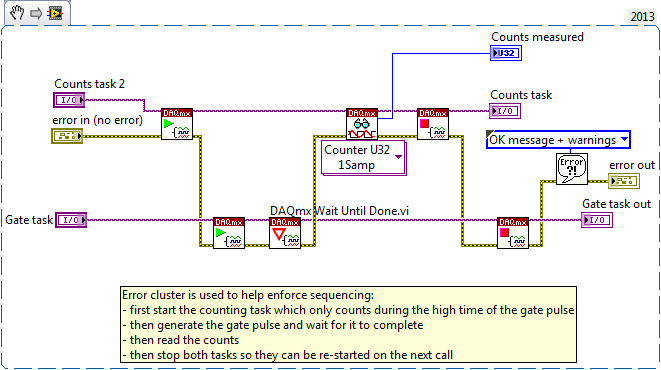
My task is to measure some random 50ns TTL pulses more small period of photodetector (PD), while its door is open for a while given only when an engine, on which is mounted a head of the PD is angles which are multiples of five. Engine is supported with an ActiveX lib, and I use the program of the event through RegEventCallback to catch when the motor reaches the angles 0, 5, 10, 15 and so on. In the loop, an iteration each time the callback was called (I use here the declarant to communicate between the loop and the reminder) that I use for data acquisition the next VI:
who is in the section 'Analysis' of the business structure in the loop. The initialization section of the structure of matter in the loop contains the following code:
Here, I must explain that there is no settlement at all (characteristic of the PD) without a "door task".
I continiously get the 200010 warning (not error) the DAQmxStopTask.vi form, although I've done (values non-null) measures. In my opinion, there should be something with the acquisition rate or the size of the buffer, but I can't actually get exactly what to change: 20 M is enough, 2 samples is twice more than enough (asked by LabView, however)...
Please, recommend something!
It is not particularly intuitive, but it is quite clear in the help and examples * after * you know to look for.
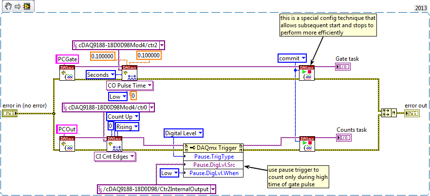
When you want to generate a single pulse gate, you just never * any * call the DAQmx Timing.vi when you configure the task to the door. The same goes for the measurement task when you only want a single measure.
I took the liberty of tweaking your two statements a bit. Have not been able to test it, so let me know if any questions or problems.
First of all, the new configuration that will use the gate pulse as a signal of equipment only limiting during the counting time:
Then, the new callback function to generate a single pulse and take a single reading:
-Kevin P
Maybe you are looking for
-
How to change engine yahoo of google search as a default startup or default mozilla page
Yesterday, my friend was install Filezilla on my pc.Then automatically my pc loads very slowly.I check my network, then I found this site below automatically(id.search.yahoo.com/?fr=hp-ddc-bd-tab & type = bl-bfr-ob-rhb-33__alt__ddc_dsssyctab_bd_com)T
-
Firefox does not and can not open in safe mode, I continue to receive reports of incidents.I tried to reset firefox and reinstall firefox, both do not work.I have updated to windows and has completed an audit of malware that recommend firefox.This ha
-
I forgot the password question and security for MSN.
When msn has changed, I was on someone's account. Easy to get on and now the passwards guestions or security works. All contacts and e-mail required. hope im not ground
-
How to print envelopes on my Laserjet 200 M276
How to print envelopes on my Laserjet 200 M276 installed on Windows Vista