Display two signals on a graphic band
Everyone,
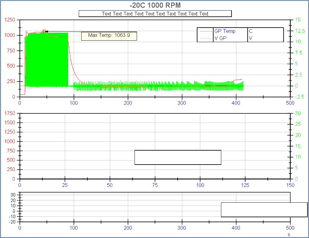
Graphic of the band have always been my downfall. Please see the image 'Simple Data Point works' to see a diagram of a program carefully trace a series of points on a graph of the band.
I thought it would be simple to add another set of data to draw on the axis Y. I just added an another data point to each picture that I feed in the terminal 'Y' in the block 'building the waveform. When I do that, nothing works.
Any help would be greatly appreciated.
Thank you!
See if that's what you're looking for...
Tags: NI Software
Similar Questions
-
How do I display two signals graphic multiplot
Hi, I am currently working on a LabVIEW program that requires me to display two signals measured by two current using MyRIO sensors OR. I am facing problems displaying two signals on dashboard of data, I know how and what should I log in the block diagram Front Panel of LabVIEW so that both signals, measured by the current sensors can be displayed on the dashboard of data?
-Introduction to LabVIEW: http://www.ni.com/getting-started/labview-basics/ and http://www.learnni.com/
-Check the labview\examples\general\graphs\charts.llb for examples of the waveform card: https://zone.ni.com/reference/en-XX/help/371361J-01/lvconcepts/types_of_graphs_and_charts/
-Examples: http://digital.ni.com/public.nsf/allkb/21E8163F259DA2058625703B007511AA , https://decibel.ni.com/content/docs/DOC-40940 , and https://decibel.ni.com/content/docs/DOC-5574 -
Displaying several curves on a graphical 2d in reports how can I force a curve to be at the forefront? I have two signals, and I want to show a bunk on top of the other. This time Diadem will be only graphic it the other way around. I tried to delete the curves and add them in different orders, change the order that they are in the list of the curve, changing their order in the data, right-click on the curve portal and selecting "move to forground" (this only moves the complete 2D graphic object in the foreground). IM using the Diadem 12.0 base.
Hello Joe,
I found what causes your curves draw in the wrong "order".
You are using two value axes and DIAdem still attracts before Y2 Y1 data, regardless of the order of the curves in the "Curve and definition of the axis" dialog box.
I enclose your layout with a little modification, I changed the order Y1 and Y2 axis (I swapped whose data is displayed on the value axis) and I get the following result:
Once I looked at your page layout, it appeared, why the order of curves does not reflect the order in which curves were drawn. I didn't - so I just learn something new here as well.
I hope that this answer to your question, do not hesitate to ask if there is anything else I can help you.
Otmar
-
How to display the signal on a waveform graph in Labview Signal Express?
Hello
I want to display a signal in Signal Express 3.0 in a "waveform table", but don't know how to do it and I think that it may be impossible?
In Labview, there are two ways to view data, a 'waveform table' or a 'waveform graph. The great thing with 'picture of waveform' is that it allows you to set a length of history and you can see the data move to the left (option graphic strip) that samples are recovered. It works perfectly.
In Signal Express I can only select "Graph XY" or "Waveform curve" by doing a right-click of the mouse, but I can't select "table of waveform. Is it really true that it is not possible to view data in a graph of waveform "with Labview? (1 analog signal during streaming, 100 samples to read at the rate of 1 K)
Thank you in advance,
Enrique
Hi Enrique.
You are right that there is currently no graphic waveform in SignalExpress. The thing nearest you can join, is saved data under a log and then he looks one when recording (which I know this isn't quite the same interactive behavior).
For your last comment, you wrote 'waveform curve', but I guess you meant 'picture' here as well.
Sorry about that. We recently received this request, then perhaps in a future version.
Phil
-
HP monitor does not display "DVi signal.
My HP LP2275w monitor does not display "DVI signal" when connected with a DVI cable (supplied), but when it is connected via a VGA cable and adapter DVI/VGA (both supplied) it works but no BIOS screen. It begins immediately with the logo of the VICTORY.
I just bought new HP Pavilion 500-158eg, Intel Core i5-4440, with AMD Radeon HD8570, 2GB processor, running on WIN7 Pro 64 b. VGA and another port of the motherboard are initially blocked so I can connect the monitor only via the output HDMI or DVI on the graphics card.
I should note that on my old machine without a name with the graphic upgrade ATI Radeon, there is no problem and I used the same cable. There was an electric shock that causes the collapse of the motherboard so I can't even re - check on the old machine. I can't verify if there is a problem with the DVI cable because all laptops in our housing have only the VGA output...
All solutions?
Concerning
Disco96, welcome to the forum.
The specifications for the computer show that they run win 8 64-bit. Downgrade you for Win 7?
Here's what the quick reference Guide shows for the monitor:
Model: (LP2275w) product #: video (KE289A4) standard: (WSXGA +) Native resolution: Aspect ratio (1680 x 1050): (16:10) types of connectors: (DVI - I, (support HDCP) DP) cable/s included: (DVI - D to DVI - D, DVI - I VGA, DP USB,)
Also, here are the i/o ports of back on the computer:
Figure 2: Rear i/o ports -
Two signals to two graphs of waveform
Hi all!
I had some problems with my data acquisition software.
I got two signals and I show two signals to two different graphic signals.
How to separate the signals?
There is an entry called "table". Just this thread in the 2D DBL table. Drag the bottom of the table Index down so that you have a second output sub-table. Wire of your graphics. Fact. No need to plug anything on the index entries.
-
Time scale does not properly after separation of the two signals of virtual channel
Hi all
I have a problem when I use a virtual channel with two analog inputs. I'm cutting the two signals into two separate tables of waveform, as shown in the attachment. The two signals seem to be reading very well, the problem is that the time scale (x-axis) begins to act on the strange. Seconds displayed time seems to keep jumping up and down at a high frequency, resulting in the two signals of displayed does not correctly in the table of waveform. Could someone please try to help me? Any help would be greatly appreciated!

Thanks in advance.
Try to acquire a signal with first time information. You can replace the DBL 2D with a data type of 1 d wave. You don't need this code extra silly - just a function of Board Index to get the separate channels.
-
A full justification and display two pages do not work correctly on iOS 10
I have installed iOS 10 yesterday on my iPad 2 Air but have found that the two functions do not work correctly in iBooks. First of all, full justification does not work when the font size is brought to a certain level. In other words, a complete justification works only when I reduce the police to a size too small. It then automatically left justification when I increase the font size to a comfortable level. This feature, however, works perfectly on iOS 9.3.5. Secondly, as already posted by a member of this community of support, the option to display two pages does not work correctly. Also, this feature stops working when the police is increased to a certain size.
Someone at - it solutions?
It is not a solution. Apparently, it's just how it is in the new iBooks. I would say that we all leave comments that we do not like it. This is a feature of iOS 10, so it won't go away unless we do a big noise about it. I just got my Mini iPad so I don't have to deal with.
www.apple.com/feedback/iBooks_iOS.html
-
Don't display two pages does not correctly in the iOS 10
I've upgraded my iPad to iOS 10 2 Air tonight, then went to continue reading a book that I bought recently through iBooks. Display two pages, when the iPad is in landscape mode, does not appear now - unless I do the police really small. If I increase the font size, while in the landscape to something more readable, I get only a single page view.
I deleted and re-uploaded the book, but the behavior is the same. I signed up in iBooks on iPad an another running ios 9.3.5 and display two pages work properly, with normal font sizes - sizes that won't let me see the same book in two page mode on iOS 10.
Apple - help! I really prefer the reading with the fashion landscape of two pages in iBooks. I can't, however, seem to get this to work with anything other than tiny fonts.
Has anyone else noticed this?
I also noticed. Any solution?
-
Firefox displays two barely legible as the default fonts fonts. These came from an email that I opened. How can I get rid of them?
You can write a check for corrupted fonts and duplicate and other police issues:
- http://www.thexlab.com/faqs/multipleappsquit.html - help book 2.0 fonts: looking for damaged fonts
- http://www.CreativeTechs.com/IQ/garbled_fonts_troubleshooting_guide.html
-
Align the two signals and measure the Phase Shift
Hello
I do an experiment in which I use the NI USB-6221 DAQ card. The jury is able to make 250 k samples/second. I want to measure two voltages in a circuit and find the phase shift between them at frequencies between 1 and 10000. First I ouputted a wave sinusoidal frequency variable through the Commission and applied to a test circuit. Then I used the Board to measure the two tensions consecutively (thus reducing the maximum sampling frequency at 125 k). I used the signals align VI and measured the two phases and then calculates the phase shift (VI attached in Phase 1). It worked well for the test circuit I built in which the phase shift went way logarithmique.20 degrees ~84.5 degrees and then stabilized. At frequencies above 5 000 Hz phase shift must have remained constant, but it varies more or less 1 degree. When the phase shift is 84.5 degrees, present a degree of variability is not particularly explicit. When I asked my program on the circuit that I really wanted to measure, the phase shift went from-. 5 degrees up to about 1.2 degrees. The change in the values of phase shift at high frequencies (> 3000) was environ.2 degrees. Given the small phase shift, this variation is unacceptable. Now I tried to use a sequence to each blood individually (increase the maximum sampling frequency to 250 k) and then align the two signals and measure the phase of each shift. When I use align it and re - sample Express VI to realign the two signals, I get the message "error 20333 analysis: cannot align two waveforms with dt even if their samples are not clocked in phase." Is it possible to align two signals I describe here? I enclose the new VI as Phase 2
Matthew,
I think I have an idea for at least part of the problem.
I took your program data and deleted stuff DAQ. I have converted the Signal on the chart control and looked then what was going on with the signal analysis.
The output of the Waveforms.vi line has two waveforms, like the entry. However, arrays of Y in the two waveforms are empty! It does not generate an error. After some head scratching, reading the help files and try things out, that's what I think is happening: the time t0 two input signals are 1,031 seconds apart. Since the wavefoms contains 1,000 seconds of data, there is no overlap and may not align them.
I changed the t0 on two waveforms are the same, and it lines up. The number of items in the tables is reduced by one. Then I increased the t0 of 0.1 seconds on the first element. The output had both greater than the entry by dt t0 t0 and the size of the arrays was 224998. Reversing the t0 two elements shifts the phase in the opposite direction.
What that tells me, is that you can not reliably align two waveforms which do not overlap.
I suggest that you go to 2-channel data acquisition and that it accept the reduced sample rate. You won't get the resolution you want, but you should be able to tell if something important happens.
You may be able to improve the equivalent resolution by taking multiple steps with a slight phase shift. This is similar to the way that old oscilloscopes of sampling (analog) worked. Take a series of measures with the signal you are currently using. The make enough average to minimize changes due to noise. Then pass the phase of the signal of excitement to an amount that is smaller than the resolution of phase of sampling rate and repeat the measurements. Recall that I calculated that for a 5 kHz signal sampled at 125kHz, you get a sample every 14.4 degrees. If shift you the phase of 1 degree (to the point/mathematical simulation), you get a different set of samples for excitement. They are always separated by 14.4 degrees. Take another series of measures. Transfer phase another degree and repeat. As long as your sampling clocks are stable enough so that frequency does not drift significantly (and it shouldn't with your equipment), you should be able to get near resolution of what you need. The trade-off is that you need to perform more measurements and may need to keep track of the phase shifts between the various measures.
Lynn
-
Hi, I try to achieve the function Sum (+) and Sub (-) with the participation of waveforms, I know the problem and the different dt when dt is the same the smooth executing operations but I want to achieve something like this Waveform sum Figure 1 as you can see if two signals with different frequencies are added between them the result looks like Figure 1 , but with the same dt different frequency is not calculated and the amount always show that the two signals have the same frequency. How can I realize the amount similar to that in Figure 1? Thank you all
Hello Silversky,
It seems you want to do something like that...
But the figure referenced never mentions the signals with different dt! Simply to create waveforms with same dt in the first place...
-
Display two tables 1 d on Wavechart
Hello
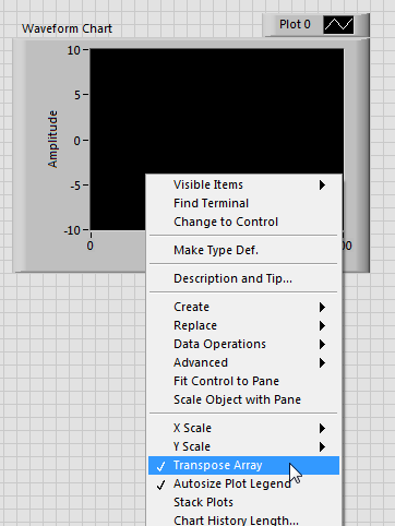
How to display two tables 1 d of the same size on a WaveChart
Thank you.
No, aid is correct, if wire you a table 2D to waveform curve, you can transpose it in the context menu as follows:
Checking / unchecking this option has the same effect than to put a 2D conversion table before you wire your table in the waveform table.
-
How can I synchronize two signals in Labview?
The first signal is a pulse index which gives the position of a reference point of the wheel (= 1 for 0 ° and signal = 0 for 1-360 °), and the second signal gives the total force meeting the wheel. The two signals have different sampling rates high. The first signal is always 360/rotation, but the second signal varies from cycle to cycle based on how fast the force is changing. The signals are in the form of two columns of numbers in an excel spreadsheet.
I would like to do such as Labview at the exit of the angular position of the reference at the time of the cycle where the wheel knows the maximum strength in degrees. Can anyone suggest a vi or a method that I might be able to use for this task? I am new to Labview, so any help is appreciated.
Hi Westerman,
I have a little trouble to understand the basics of what you're trying to do. A little more details would be very helpful pointing you in the right direction. If you want to align the timestamps/reference of the two signals time?
I've included a link to a document that describes generally how encoders (I guess that your pulse index indicates that you are using an incremental encoder) can be used in LabVIEW.
http://www.NI.com/white-paper/7109/en
You should also try the search the forums for questions relating to the use of a rotary encoder in LabVIEW. I was able to find several with the included code example.
Feel free to provide us with a few details and we'll help guide you.
Andy C.
Technical sales engineer
National Instruments
-
200560 error during the generation of the two signals of AO
Hello
I am trying to send out two signals and I get error 200560 to "wait until done" vi.
I was wondering if there is no solution for this problem.
BTW, the vi is attached.
Thank you
Pooya
You have your clock set to continuous samples. I don't know if you can use 'Wait until what' If you the task will never happen. Set your click on over and see what happens.
Maybe you are looking for
-
1.2 PlainOldFavorites disabled on the last update!
ETA for an update? I can't use FF without it!
-
Windows Update includes the Toshiba driver updates?
Hello Windows Update includes the Toshiba driver updates? And if yes, do you know what drivers are included in Windows Update and that would be excluded? Thank you...
-
problem with Agilent GPIB 8510C Network Analyzer
Hello I downloaded the Plug and Play (project-style) driver for Agilent 8510C Network Analyzer. The basket has address suite: Address of HP - IB 8510: 16 The system bus address: 21 HP - IB source address: 19 Criterion address HP - IB: 20 Plotter HP -
-
Is it possible to view the properties of the class defined by the user as a hierarchy
So I drag a property node and right-click to display the list of all possible properties. They are well organized into groups and subgroups etc... Is it possible to do the same for the properties I defined for a class? Let's say I have 20 propertie
-
Can I make my Vonage phone service and always access the internet through MSN Premium
Can I make my Vonage phone service and always access the internet through MSN Premium