Draw a line between two entities
Hello. I am on the Data Modeler and I use the Visual tool. I want to connect 2 entities with just a line that I can add comments or notes. I can create a relationship of foreign key between 2 entities now, but a primary key is required to do this. Some of my tables do not have primary keys, but I need to put a line between them, with comments or notes saying what relations there are. I know that the software is by default to foreign key relationships via primary keys, but I need to draw my own in there. Any ideas? Thank you!Yes, this is a frequent question on the forum. Once you draw the line, he opens a straight dialogue/property box? On the left, you will see a node called related columns. Click on that. You will see the map with the column name that is generated in the child column field. Click on that column and you'll see that it really is a drop-down selection list, which will show you all the FK "candidate" columns already in the table. One of them will be hopefully the FK column that you want to attach. Pick it up. When you click on apply or OK, the tool will ask you if you want to remove the generated column. Select "Yes".
Note: the drop-down list won't give you the possibility to select the columns having the same exact data type and column PK of the source size. If the column that you want to attach to the is not an exact match, the tool will not let you join her. I had a situation where my PK was a surrogate Number key (9), but the target FK column was Number (6). I had to change the definition of column target in order to define the FK in the model. (So I added a note on the column of this change and why I did it). Unfortunately the model is now synchronized with the Pb of the production. Finally, we must convince the DBA to make the change (unless it's a third-party to which application cases you will have to live with it).
Tags: Database
Similar Questions
-
How to draw a line between two buttons?
Hello.
I want to do two mobile buttons attached to a line. When changing the position of any button you change in the appearance of the line of course. I know how to draw a line, but after MOUSE_DOWN and I don't know how to remove an old monotube and how this line to appear all the time?
My code
btn2.addEventListener (MouseEvent.MOUSE_DOWN,
mouseDownHandler3);
btn2.addEventListener (MouseEvent.MOUSE_UP, mouseUpHandler3);
btn3.addEventListener (MouseEvent.MOUSE_DOWN, mouseDownHandler3);
btn3.addEventListener (MouseEvent.MOUSE_UP, mouseUpHandler3);
Set a mouse down Manager (the user is dragging)
function mouseDownHandler3(evt:MouseEvent):void {}
var object = evt.target;
We have to limit them by dragging to the area inside the canvas
object.startDrag ();
}
function mouseUpHandler3(evt:MouseEvent):void {}
var obj = evt.target;
obj.stopDrag ();
spisujemy x, y
var x2Pos:Number = btn2.x;
var y2Pos:Number = btn2.y;
var x3Pos:Number = btn3.x;
var y3Pos:Number = btn3.y;
trace (x3Pos);
trace (y3Pos);
var roundObject:Shape = new Shape();
roundObject.graphics.lineStyle (2, 0 x 990000,. 75);
roundObject.graphics.moveTo (x2Pos, y2Pos);
roundObject.graphics.lineTo (x3Pos, y3Pos);
this.addChild (roundObject);
this.removeChild (this.getChildAt (this.numChildren-1));
}Source. FLA: http://www.mediafire.com/?y2tyzz4zxun
Here is a solution that you can adapt for two or more buttons...
var btns:Array = [btn2, btn3]; instances in concert
handlers all btn
function setBtns (): void {}
for (var i = 0; i)
inclinometer [i] .buttonMode = true;
inclinometer [i] .addEventListener (MouseEvent.MOUSE_DOWN, grab);
inclinometer [i] .addEventListener (MouseEvent.MOUSE_UP, drop);
}
}setBtns();
inspired by ECCAS btns lines all while occurs wildfire
function drawLines(e:Event=null):void {}
Graphics.Clear;
graphics.lineStyle (2, 0xFF0000);
((graphics.moveTo(btns[0].x+(btns[0].width/2), btns[0].y+(btns[0].height/2));for (var j = btns.length - 1; j > = 1; j-) {}
((graphics.lineTo(btns[j].x+(btns[j].width/2), btns[j].y+(btns[j].height/2));
}
}managers
function grab(event:MouseEvent):void {}
event.target.startDrag ();
addEventListener (Event.ENTER_FRAME, drawLines);}
function drop(event:MouseEvent):void {}
event.target.stopDrag ();
removeEventListener (Event.ENTER_FRAME, drawLines);}
drawLines();
-
Draw a line connecting two points in the WPF chart
I'm trying to understand the best way to draw a line between two existing points on my graph in WPF. At first, I thought I had it works fine; I just added another parcel to my graph then given exactly two points for rendering. But I quickly noticed that the app has become surprisingly slow and CPU was quite high (adding other plots does not affect the use of the CPU as long as they have a complete set of points (?)). He wants me if I looked at using the DataToScreen method on the chart but I can't know what the parameters are. The second parameter is simply an IList that tells me a lot. This seems to be the method I want to use for the coordinates of a point on the graph screen.
No one knows what the second parameter is supposed to be for the DataToScreen method? Everything I tried throws an Exception of Argument.
Thank you
DanDataToScreenwill return a screen coordinate in the plot area of a chart of the value of the raw data horizontal and vertical in the given list. The parameter value is aIListfor compatibility with other methods of graphical query such asFindNearestValue, returnIListvalues containing raw data.A concrete example, say you had a graphical configuration with a wide horizontal axis ranging from 0 to 100 and a vertical axis double precision ranging from 10 to 20:
To get the screen coordinates of the value at the center of the two axes, you can call:
graph.DataToScreen(plot, new object[] { 50, 15.0 })Note that the raw data values corresponding to the type of axes (horizontal
AxisInt32returns the integer50and verticalAxisDoubleGets the value15.0).You also mentioned a performance issue where "adding other plots does not affect the CPU so that they have a complete set of points". I did a simple test app that adds an array of two points of a chart on each key (for example
graph.Data.Add(new[] { new Point(x1, y1), new Point(x2, y2) });), but could not reproduce the problem you saw. Could you share the code, you use to draw the connection line? -
draw the line between black pixel: coordinates of the selected pixels?
Hello
I want to build a script that can check a Photoshop file and:
-find the black pixel
-for each black pixel, looking for an another black pixel at a maximum distance of 5 pixels
-then draw a line between the two black pixels.
I wrote this script below (my first script...), but it's VERY slow (and my final image is VERY large), I think because I test the color for each pixel in the image.
So an alternative would be to select a black pixel with the wand, then the script record all the details of the selected pixels, then my script wil test only the pixels (less than 1% of the pixels are black in my image).
Is this possible with JavaScript?
Thank you for your answer!
Marc
function main(){
 var startRulerUnits = app.preferences.rulerUnits;
 app.preferences.rulerUnits = Units.PIXELS;


 var myHeight = app.activeDocument.height;
 var myWidth = app.activeDocument.width;


// Find black pixel
 for(var i=5; i<myWidth; i++) {
  for(var j=5; j<myHeight; j++) {
   activeDocument.colorSamplers.removeAll()
   var sampler = activeDocument.colorSamplers.add([new UnitValue (i, 'px'), new UnitValue (j, 'px')]);
   if (sampler.color.rgb.hexValue === "000000") {


// For each black pixel, search another black pixel below left up to 5 pixels
    for (var m=i-5; m<i; m++) {
     for (var n=j+1; n<j+5; n++) {
      activeDocument.colorSamplers.removeAll()
      var test = activeDocument.colorSamplers.add([new UnitValue (m, 'px'), new UnitValue (n, 'px')]);
      if (test.color.rgb.hexValue === "000000") {


// Then draw a black line between the two black pixels
       var FillColour = new SolidColor;
       FillColour.rgb.hexValue = '000000';
       var ad=activeDocument;
       ad.selection.select([[m,n],[i,j],[m,n+1],[i,j+1]], SelectionType.REPLACE, 0, true);
       ad.selection.fill(FillColour);
       ad.selection.deselect()
      }
     }


// For each black pixel, search another black pixel below right up to 5 pixels
     for (var m=i+1; m<i+5; m++) {
      for (var n=j; n<j+5; n++) {
       activeDocument.colorSamplers.removeAll()
       var test = activeDocument.colorSamplers.add([new UnitValue (m, 'px'), new UnitValue (n, 'px')]);
       if (test.color.rgb.hexValue === "000000") {


// Then draw a black line between the two black pixels
        var FillColour = new SolidColor;
        FillColour.rgb.hexValue = '000000';
        var ad=activeDocument;
        ad.selection.select([[i,j],[m,n],[m,n+1],[i,j+1]], SelectionType.REPLACE, 0, true);
        ad.selection.fill(FillColour);
        ad.selection.deselect()
       }
      }
     }
    }
   }
  }
 }
}
main();
If someone wants to do the same thing, the ImageJ software works very well on very large images (1 billion pixels) by the process according to > binary > close
-
I want to draw a line between 2 specific points on an image inserted in a Panel? Help, please!
I am a beginner in working with LabWindows/CVI and I want to draw a line between 2 specific points on an image inserted in a Panel? Please help or examples of code.
As evidenced by the Wolfgang there is a problem in the definition of recall. InstallCtrlCallback wants a reminder of the standard of review as a parameter: apparently you have structured your reminder callbackName on the prototype of a recall of Panel, which obviously missing the setting "control".
In addition, the recall of control should be said somewhere before it can be used. In other words, you must add his statement before your function {main}, either in one of your include files, or directly in the code. This is the reason for the error 'found int, whereas CtrlCallbackPtr. '
Third point: you create a new picture control in the callback assigned to the image control. And you reuse variable 'Test', which already holds a valid control ID...
Finally: what you expect to make from '1' in callbackData parameter, given that you do not use anyway? Unless you want to adapt the behavior of recall some past in callbackData conditions, you must pass NULL as the parameter.
-
Hello world
I wrote this little program where iam creating two label and I can drag this label and this works perfectly.
I also try to include a line between this label. I am not getting the correct result because I see my tag, but not the line. (I know that my program is incomplete to separating it from the label, since I can't see the line with label iam not able to proceed)
I am a newbie so my code is perhaps not too professional. Hoping to find a few tips.
Thanks for all your time and help.import java.awt.*; import java.awt.event.MouseEvent; import java.awt.event.MouseListener; import java.awt.event.MouseMotionListener; import java.awt.geom.Line2D; import javax.swing.*; @SuppressWarnings("serial") public class test extends JFrame implements MouseListener, MouseMotionListener { private JPanel panel = new JPanel(null); private JLabel label1 = new JLabel(); private JLabel label2 = new JLabel(); private int mouseX = 200; private int mouseY = 100; private boolean drag = false; public test() { this.add(panel); panel.setBackground(Color.WHITE); panel.add(label1); label1.setOpaque(true); label1.setBackground(Color.BLUE); label1.setBounds(mouseX, mouseY, 100, 50); label1.addMouseMotionListener(this); label1.addMouseListener(this); panel.add(label2); label2.setOpaque(true); label2.setBackground(Color.RED); label2.setBounds(mouseX + 200, mouseY, 100, 50); label2.addMouseMotionListener(this); label2.addMouseListener(this); } @Override public void mousePressed(MouseEvent e) { if (e.getSource() == label1) { drag = true; } if (e.getSource() == label2) { drag = true; } } @Override public void mouseReleased(MouseEvent e) { drag = false; } @Override public void mouseDragged(MouseEvent e) { if (drag == true) { JComponent jc = (JComponent)e.getSource(); jc.setLocation(jc.getX()+e.getX(), jc.getY()+e.getY()); } } public void mouseMoved(MouseEvent e) {} public void mouseEntered(MouseEvent e) {} public void mouseExited(MouseEvent e) {} public void mouseClicked(MouseEvent e) {} public void paint(Graphics g) { Graphics2D g2 = (Graphics2D) g; Line2D lin = new Line2D.Float(100, 100, 250, 260); g2.draw(lin); super.paint(g2); } public static void main(String[] args) { test frame = new test(); frame.setVisible(true); frame.setSize(600, 400); frame.setResizable(false); frame.setLocationRelativeTo(null); frame.setDefaultCloseOperation(JFrame.EXIT_ON_CLOSE); } }
Outside of the Netbeans IDE is also there another tool that can help in creating faster GUI swing application.public void paint(Graphics g) { super.paint(g); Graphics2D g2 = (Graphics2D) g; Line2D lin = new Line2D.Float(100, 100, 250, 260); g2.draw(lin); }Also I suggest
public void mousePressed(MouseEvent e) { if (e.getSource() == label1 || e.getSource() == label2) { drag = true; } } -
Thick border line between two columns
Hello all;
I have a requirement where the user must be able to distinguish between two columns hnce asking a thick line, rather than the usual 'by default'.
Everything is 'Default' until then.
I clicked on properties of the 1st column and in the section "Border", I chose "Custom" and made the right wall of the cell in black color.
I see a thick border now, but it has eliminated the 'default' border separating lines. His party make the entire column look like a single cell.
I don't want any change with the exception only of the border of a column of a black line.
Any help is greately appreciated.
Thank you!The column properties-> Options of Style CSS custom (HTML only)-> use custom CSS Style->
the following CSS code
border-right-width: 1px; border-right-color: green;or go with someone with the necessary changes
Appreciate if you score as correct if it works
Published by: Srini VIEREN on December 11, 2012 16:43
-
Straight line between two polar points
Hi all
I created a VI that could be traced a Polar curve according to time-distance formula. The VI has present Mag and target Mag. each with its own angle (Polar form that is (r, theta)). I want to draw a straight line from the current point to the target point. I used the time-distance formula to trace the scale and used the same slope to point the angle. However, I get a curved path as shown in the attachment.
Could someone tell me what formula can be used to draw a straight line from the current point to the target point?
Thank you.
1 convert two polar points in rectangular coordinates.
2. generate the points between the two. You can use the function of ramp or some other methods to generate points.
3 convert points to polar coordinates and draw. Nice straight line!
Of course, the question is why do you want a straight line when you use the polar coordinates? He will not directly be r or theta.
Bruce
-
How to create sharp lines between two text boxes?
I create a book that is written by several people, and so I want to create a "chapter... author.
Like this:
Chapter 1... Jon Doe
chapter2 ................................. Simon Harper
so that these points have always the same distance.
Help, please!
Well, if your 'chapter' and your 'jon doe' is in the separate text boxes, then there is no easy way to do it. (You could draw a bunch of lines dotted, which isn't difficult, but the only way to standardize manually drag the lines around).
However, if "chapter" and "jon doe" is in the same text box, separated by a tab character, then it is quite easy. Have you used a ruler before tab? This gives a test:
(1) type a brief sample in a text area, like the one in your post, but instead of separate columns with points, simply use a single tab
(2) select all text
3) go to the Type-> tabs
(4) I hope it sounds familiar to you (probably from MS Word, or maybe
using a typewriter) but otherwise,. (4A), click once on the sovereign to insert a tab stop
4 (b) type a question in the area of 'leader', and
4 c) press Tab or Enter to confirm
FYI, it's what you want, a 'leader' or a 'leader of dot. Knowing that he has called a "Chief" will help you find it in InDesign help.
-
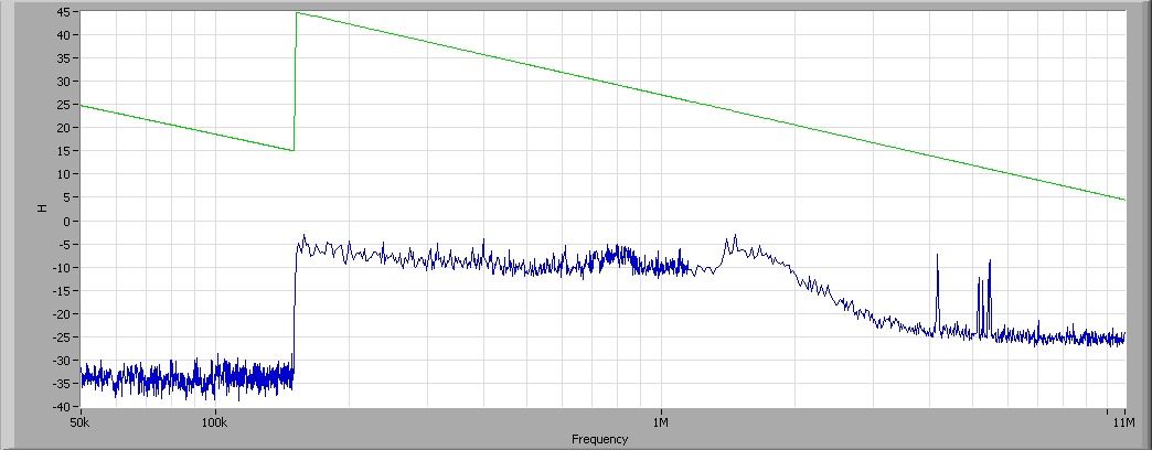
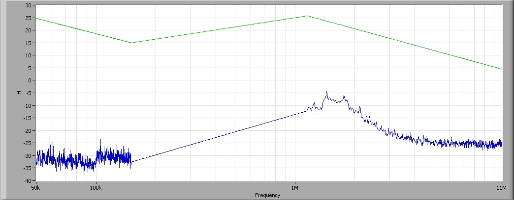
line between two parts of a graph
Hello
I have a problem with my XY graph. Here it is:
-My acquisition is completed on several frequency bands, each band is merged to the curve. It works perfectly as here:
Here, I made the acquisition on 4 strips: 50 k - 100 k. 100 k - 150 k, 150 k-1, 15M and 1, 15M - 11M.
But here's the acquisition even without the 150 k-1, 15 M
You can see the lines in this band. How can I avoid them? (they are also there when I leave a band high frequency to a band of low frequencies, and it's horrible).
Thanks in advance
One pair of NaN will break the line on a XY Chart. You can also trace the parts separately. Only their colors/line types the same kind that they seem to be the same plot. This tip is often used when the color highlighting of the sections of a graph.
-
Problem by drawing a line dynamically
Hello. I want to draw a line between two points in a dynamic way, it's average, by clicking on a canvas the first time will give the origin of the line and clicking will give once again, the end of the line (segment/stroke). I'll appreciate any help with this issue. Thanks in advance.
Hello
pls find the solution of your problem with the code below and let me know if you have any problem.
Main.MXML
"Layout ="vertical"verticalAlign ="middle"xmlns:local =" * ">
DrawingCanvas
Width = "400" height = "300".
creationComplete = "onCreationComplete () '"
"xmlns:local =" * ">
private function onCreationComplete():void
{
this.addEventListener (MouseEvent.MOUSE_DOWN, onMouseDown);
this.addEventListener (MouseEvent.MOUSE_MOVE, onMouseMove);
this.addEventListener (MouseEvent.MOUSE_UP, onMouseUp);
}
private var isMouseDown: Boolean;
private var counter: number = 0;
private var myShape: Shape = new Shape();
private var : Point of origin;
private var : destination Point;
private function onMouseDown(event: MouseEvent):void
{
isMouseDown = true;
origin = new Point (event.localX, event.localY);
}
private function onMouseMove(event: MouseEvent):void
{
if (isMouseDown is true)
{
destination = new Point (event.localX, event.localY);
var lineThickness:Number = 2;
var lineColor:Number = 0 x 000000;
var lineAlpha:Number = 1;
myShape.graphics.clear ();
myShape.graphics.lineStyle (lineThickness, lineColor, lineAlpha);
myShape.graphics.moveTo (origin.x, origin.y);
myShape.graphics.lineTo (destination.x, destination.y);
}
}
private function onMouseUp(event: MouseEvent):void
{
this.rawChildren.addChild (myShape);
isMouseDown = false;
}
]]>
with respect,
Mayeul Singh Bartwal
-
line set between two icons on the toolbar.
Hi all
How to create the line between two icons on the toolbar? help out me thanks in adavnce.
SarahHi Sarah!
You can't create a separator menu item in the top menu.
Create a submenu and put all your toolbar menu item.
Between the items that you want to have a line, create a sepatator menu item
Properties: Visible in the menu: No. and visible in the menu bar horizontal: Yes.Concerning
-
funny things happening when you draw a line
We're talking Ai CS5.
I have a work plan with a mixture between 2 wavy paths, the kind of thing that you hope that the customer will not ask new :-)
A path is in line with a horizontal guide at the top on the artboard and down by another.
I draw a line between the two guides and nowhere segment near the mixture and expect to get just a boring straight line. Instead I'm out a lengthened version of the plantings, starting at the top with the first path and passing all stages of mixing arriving downstairs with the second path.
Sorry, I have to describe it that way, but when I tried again once it no longer works, so I can't show you the result. Can someone explain what's happened here?
TIA
Steven
Looks like you were in the Mode of insulation of the Blend object - you could accidentally entered this mode without realizing it by double-clicking on the object of the mixture. Now when you draw a simple line, the mixture is getting redesigned because now he sees 3 trails blend instead of the 2 paths.
I hope this helps.
-
I know that it is possible to make the text wrap around an image, as described in the link below. But is it possible to place an image in a line between two paragraphs without split text in two text boxes?
Make the text around a picture
You can put two text boxes and the image within a parent zone to achieve a similar effect, but you can not place the image inside directly inside a text box.
Hope that helps and thanks for using the Reflow!
Chris
-
Blank line between lines of query output
Is it possible to add a blank line between two rows of the query output?
Sanjayuser12957777 wrote:
Is it possible to add a blank line between two rows of the query output?Sanjay, it's a problem of client - customer is responsible for rendering data. If whites are needed, then the customer must make as a result.
Under the projection of the cursor SQL is not a good idea.
Maybe you are looking for
-
Toshiba CT-90288: change the default 4:3 screen display
"CT-90288" isn't the TV model, but the type of the remote control. Can you please send your TV model? It is written on the back of your TV, on the nameplate...
-
Is it possible to remove an application from the appstrore? How can I do?
-
Hello I work with the axCWIMAQViewer1 where control image is updated every time that a new image of a camera happens (every 100 ms or more). After the control is updated I'm a match pattern, then call the DrawPatternMatch and DrawText draw the found
-
IE7 will not load and a problem in windows Explorer
I have 2 problems. 1. my internet explore will not install. It starts, but then stops. 2. I get an error "Windows Explorer has encountered a problem and needs to close" when I open a particular file. I am running XP SP3 and get the following error...
-
Installation of the Blackberry Smartphones blackBerry 9790 Email problem
BlackBerry has just updated my service plan and remove the addresses of e-mail on my phone to only allow me to use a [email protected] account. So I registered a new account, but the email application allow me to remove the old address, so whe