DV - 32 kHz or 48 kHz sequence?
I tried looking for things before posting, but I've seen conflicting opinions on this.
I've got a few SD DV tapes I capture and editing in CS4. I think that most of them is 12 bit audio resulting in 48 kHz. If the destination format is a SD DVD, no matter if I put the sequence as 48 kHz? An announcement of States which, since it ended up being converted, it does not matter.
Or is it better to determine the flow of the spring and then match the sequence? So if it's 12 bit audio choose 32 bit and if audio 16 bit 48 kHz?
Because I am not sure that all tapes are 12-bit, if I don't lose quality by simply using a 48 kHz sequence I guess that's my preference.
Thank you
BJBBJB1
Yes. In this case I choose a 48 KHz 16-bit project and let PrPro take care of things from there. In most cases, he may ingest a certain Audio files of different appearance standard and comply with them. If you are having problems, just rip the Audio and in SoundBooth, Audition or free Audacity, make a Save_As PCM/WAV 48 kHz 16-bit and than import.
Good luck
Hunt
Tags: Premiere
Similar Questions
-
Premiere Pro CC 2014 loss of image and text quality
Hello
I experienced some problems with the PP CC recently and I don't really know why.
Here is what happened:
I started a new project and import a Photoshop test image (.png); the image is 480px high and wide 870px (roughly the dimensions for a standard DV - NTSC widescreen 48 kHz sequence). I then created a sequence by dragging in the timeline. In the Preview Panel, I got this:

Note that the text is good and crisp. After that, I created a sequence:


I gave up the test image in the chronology of the sequence 5 and here's what I got:

It can be hard to notice, but decreased the quality of the image. (the Preview Panel is the same if the scale to the size of block option is enabled or disabled)
Here is a side by side for a better understanding:

I repeated the process with a random image on my computer, and here are the results:
 Image, dragged in the timeline
 image, dragged in the sequence (sequence same settings as above)
The same problem occurs with titles:
 the preview for the sequence 5 and 6 of the sequence are identical. (not the best quality)
I don't really know what to do. If anyone has any suggestions, please let me know.
I updated the software and it works fine. Thank you very much!
-
"Voice recording" sees Zoom H1 in 44 kHz but not 48 kHz
10.2.2 FCPX
Mac OS X 10.10.5 (Yosemite)
2.5 GHz Intel Core i7
16 GB 1600 MHz DDR3
I'm on a new machine given to me by my employer, and now I have this problem (sigh). When I try to use my Zoom H1 as an external microphone, FCPX will see any audio when the recorder is set to 48 kHz. We see very well when set to 44 kHz, but not 48, and I need 48 since that's what my Canon DSLR recorded for audio.
Any tips?
Check to make sure that the Zoom mic is set correctly as an audio interface in utilities > Configuration Audio and Midi. If you need help setting up the Zoom, see the help documentation in the Help menu Setup Audio Midi > configure audio devices. In the environment "it works" Mac, you can generally just plug into any compatible device and who generally default to 44.1 kHz/16 bits wide. The Zoom, I think, is compatible with resolutions up to 96 kHz/24 bit.
-
Audio playback and ATV4 of the ALAC 24 bit/96 kHz
Question: Can the Apple TV 4 play ALAC files 24/96 or should we downsample hi-res audio to 48 kHz?
Playing an ALAC 24-bit / 96 kHz (m4a) file via Plex Media Server running on a Synology Diskstation to the Apple TV4 presents itself as 48 kHz on the preamplifier.
I had read in a few places online that if Plex feeds the ATV4 an audio file of the ALAC (as opposed to a FLAC) Plex would indeed send 24/96 because the Apple TV4 would accept a bit for bit ALAC. This doesn't seem to be the case. I'm doing something wrong? I guess I'll ask this course at the Plex forum too.
(everything is upgraded to the latest version)
I'm not aware that she is able to do, something which I think is limited by the software, not the hardware.
As high definition audio is not sold by Apple I think that's not on their radar screen...
-
Bad quality of sound with lightning adapter / 44.1 kHz / iOS 9.2
Hello
I bought a new
Lightning 30-pin adapter (0.2 m) http://www.apple.com/de/shop/product/MD824ZM/A/lightning-auf-30-polig-adapter-02 m? page = 0
but the sound quality is very poor. The music are very distorted and seem cheap.
I tested it with the spotify app (premium) and music from apple.
I discovered, that the sound quality of MP3s with 48 kHz rather than 44.1 kHz sounds good.
I don't think that the adapter is faulty, because I already tested two of them.
I also have the same problem with an iPad Air and two other car systems. So I think it has something to do with iOS 9.2 because I couldn't find any complaints about the poor quality of the CAD in the adapter in lightning.
Is there a soultion to this problem? Or can someone confirm this bug? Thanks in advance.
I also tested with iOS 9.2.1 and 9.3 beta - no solution. very bad
Not there at - it no a solution for this - apple support?
-
Hi people,
I have a challenge I'd like to discuss with you and hope to have some ideas and maybe a solution.
I have a systems acquisition (DAQ) Multifunction National Instruments NOR-PCIe-6353 means X-Series!
I would like to generate and measure signals pulse width modulation .
DRIVER:
OUTPUT:
FREQ: 0, 1 Hz - 1 MHz
Duty: 1-99%
Change the setting on the fly
(This works very well and is implemented)
ENTRY:
FREQ: 0.1 Hz - 40 kHz
Duty: 1-99%
Method of measurement: period of semi / ContinuousSamples / AsyncCallback
Here, I have problems I am running only on an Intel Core 2 Duo CPU E8500 @ 3, 16GHz.
And I want to run 2 PWM_IN and PWM_OUT 2
Low frequency work fine!
0.1 Hz - 20 kHz
It is a loopback with
myCounterReader_1.BeginMemoryOptimizedReadMultiSampleDouble (2, myCallback_1, myPWM_IN_1, myPWM_IN_1_Data);
Data = myCounterReader_1.EndMemoryOptimizedReadMultiSampleDouble (ar, on myPWM_IN_1_Data_actualNumberOfSamplesRead);
A higher frequency do not work very well!
20-40 kHz
I get exception Code of State-200279:
Attempted to read samples that are no longer available. The requested sample was already available, but has since been replaced.
Increase in the size of buffer, most frequently the reading of data or by specifying a fixed number of samples to read instead of reading all available samples would correct the problem.
Property: Value of NationalInstruments.DAQmx.DaqStream.ReadRelativeToRequested:
NationalInstruments.DAQmx.ReadRelativeTo.CurrentReadPosition
Property: NationalInstruments.DAQmx.DaqStream.ReadOffsetRequested value: 0
Task name: NI1_PWM_IN_ctr0
State code:-200279
40 kHz, period is 25us = 12, 5 HighTime and 12, 5 LowTime 50% DutyCycle
This means that each 25us I get a reading of 2 samples the HighTime and the LowTime
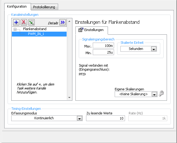
I charge my task of Max, so here's the Setup (sorry its german):
1 can someboby you explain to me what the MemoryOptimized?
2 Zu lesende values means that the size of the buffer 10 is not much but increases the size of the buffer to say 10,000 needing help on
a longer time!
3. playback of data more frequently is not possible because the data are under tension, because it is
4 specify a fixed number of samples I der number is HighTime 2 and LowTime
5. I have does not start and stop the task! Is it better to start and stop the task each time while I still may have a new buffer?
I hope someone has an idea for!
By
Steven
Reading with 50 software we period - bad idea, you will jump impulses. Try to use DAQmx Read Overwrite property, set it to "crush the unread samples" - it will overwrite the impulses without error.
-
Pulse ultrasonic 40 kHz and the time before receiving the pulse.
Hello
I developed the following circuits:
TX: a Circuit that generates a 40 kHz of frequency using a LM555, the LM555 is connected to a gate AND who, when you use the test on MyDAQ Panel (6216) I put cntr0 and set it to the detection of edge I can count the number of detections of edge when I activate the port up and when I turn it on it low stop recording of the counties.
Rx: Reception Circuit contains an op amp that is introduced in a LM567CN tone decoder which is set at 40 Khz. when the receiver PLL circuit locks on the 40 kHz signal switches LM567 pin 8 output ground.
Question: I am NEITHER very new and ask yourself where the starting point would be to create a VI that will trigger the Tx circuit, and then measures the time required for the circuit of Rx to receive the signal, this intitial will carried out through the air and then I want to move it through a meduim such as water. Someone at - he tried or seen anything that would be useful to create a vi that correspond to this.
Any help would be greatly appericated.
Phil
Using a myDAQ or a 6216? You mentioned the two... I'll assume 6216:
You'll want a task of separating two edgeand also a task of digital output.
The digital output control signal enable for the LM555. Connect from the digital output line at your door AND as well as a PFI lines on the 6216 (this will be the "first" edge). Connect pin 8 of the LM567 to a different line of the PFI on the 6216 (the 'second' edge). You can configure the polarity up/down via the Create channel VI (looks like your second advantage is going to be 'falling').
Programming would be as follows (in order):
1 configure the tasks as shown in the related examples (i.e. channel to create / configure synchronization).
2. start the task of digital output.
3. write the 'low' digital output to ensure that it is initialized.
4. start the task of separation on both sides (it should be buffered as in the example linked even if you are only reading a sample).
5 write the digital output 'high '.
6. reading (a sample) the task of separation on both sides. Specify a time for read long enough to ensure that the falling edge is considered.
7. write the 'low' digital output (assuming that you want to disable the Tx when you are finished with the test)
8. stop and disable the two tasks.
The measured result will be a 12.5 ns resolution using the time base 80 MHz by default on the 6216.
Best regards
-
Hi all
I use the NI PCI 6723 Analog Output card with SCB-68 connector housing. Specifications of the PCI-6723 tells this unique channel of sampling frequency (refresh rate) maximum is 800 Ksamp/s. I tried t0 generate sine wave 100 KHz using single channel only in continuous mode with + / 10V range defined using Labview Signal Express application, however, output of the DAC was very distorted (a kind of triangle instead of waveform sinusoidal waveform) and amplitude of output even reduced to about 2 or 3 V and becomes not symmetrical (i.e. not centered around 0V).
Then I found that the generation of signals up to 20 kHz, output DAC was very well without any distortion amplitude or form, however as I go beyond 20 kHz (with constant update of rate of 800Ksamp/s) to 100 KHz, CAD production has started to become more, and most corrupt.
Kindly tell me if NI PCI-6723 is sufficient to 100 kHz signal output if I use only single channel?
And if so, what can be the reson for this distortion?
Thank you
Best regards
Asim
It seems that you exceed the maximum scanning speed for the card, which is probably why you see distortion on your waveform. Scanning speed is defined as the maximum rate of change of output voltage per unit of time. The map (from the manual, link below) has a maximum speed of scanning of .7V / us, you are exceeding that by a significant margin.
NEITHER 6722/6723 specifications
http://www.NI.com/PDF/manuals/370822c.PDF
To resolve this problem, you can either reduce the frequency of your signals output, or you can decrease the amplitude of the wave. the two changes will reduce the scanning speed. You will need to reduce one or the other enough will be the maximum scan rate specified map.
So, long story short, the card is not able to produce a sine wave of full scale at 100 kHz due to the limitation of the maximum scanning speed. You should be able to output a signal 100 kHz if you reduce the amplitude of your waveform.
Kind regards
-
Hello
I'm reading values from rates to sample different RF bands DBL and using the value to create a file header to store binary data complex 32IQ to the file. I use the format based on string to do, but I still want to be represented in kHz, the sampling frequency and I have not thought of a way to force it is always the case. I use a format string of %.3p which, for sampling rate as 13125 and 400000 he returns 13,125 k and 400,000 k respectively, and that's what I want. However, one of my groups is 3750000 Hz and the format to a string returns Mr. 3,750, I would come back 3750,000 k instead. Does anyone have any ideas on how I might accomplish this?
Thank you
Tim
If you divide the value by 1000 dbl and then apply the format to a string with the specifier %.3f you the kHz value.
Ben
-
generate trains of pulses of 5 kHz
Hello
I would like to generate digital impulses to 5 kHz oe less rate, any recommendation of material? better usb and budget type.
I have usb 6501, I try to work on this, maximum output is 1 kHz the best. Is it possible to above?
Appreciate any help here.
Kind regards
Simon
You can use each channel to generate the train of pulses at a different frequency at the same time, and generation of pulse stops immediately as soon as the task is stopped.
-
50mV peak output of sine similar, f = 10 kHz
Hello!
Yesterday, I found that when I create an output signal sinusoidal similar (with a program labview or M & a test panel) the sinus has a 50mV peak when it changes sign (+/-)
I use a USB-6212
LabVIEW 8.6
example of frequency: 200kS/s
sinusoidal frequency: 10 kHz
The peak is always there to 1000 Hz (stil 50mV), but I do not see for the frequency of 10 Hz.
The advanced amlitude does not change for the Amplitudes between 1V to 10 mV.
I see the same glich on AO-0 and AO-1, and it's always when the sinuses = zero.
You know: ' what is it?"and the most important: what can we do about it?
I have attached a picture of the vertices for a sinus with amplitude 10mV.
Application of a filter to exit the peak would be my last resort, but this does not seem like the way to go.
Thank you very much
Higgins
This glitch (epi) is typycal for some (simple) CAD models. A simple RC filter can help. Bonny Baker wrote that an article in EDN to this topic and an article on this topic or is also to ni.com somwhere...
-
With the API c for linux, how can I decimate the clock at a 10 kHz signal?
Hiya. I know that the clock signal is decimated on the chessboard in a few places... is there a function in the linux api c for export a decimated signal? Can I choose any arbitrary decimation, or am I limited to the various bases of time used on the map (a series of M in my case)?
Thank you!
You use DAQmx (8.0 or 8.0.1)? If so, you have a few options:
Counter output: Available frequencies are {80 MHz, 20 MHz, 100 kHz, external} / {2: 2,32-1}
Output frequency: Available frequencies are {10 MHz, 100 kHz} / {01:16}
Export clock of AI or AO task: Available frequencies are {external 20 MHz, 100 kHz,} / {2: 2,32-1}, but going too fast will result in a material synchronizing error on ADC or DAC.
On the M-series: DAQ there are two counters, a single frequency output, HAVE a single timing engine and a single engine timing AO (if your motherboard supports AO). Simply choose any subsystem available to you. If you have need of a constant 10 kHz and then the frequency output is perfectly adequate, it is programmed similar to a meter output (reference Dev1/freqout instead of Dev1/ctr0).
If I remember correctly (I'm on Windows for now), on Linux the C ANSI DAQmx examples should be installed in \usr\local\natinst\nidaqmx\examples. It should be an example of output included continuous meter.
Best regards
-
Can the USB-6210 output signal square 10 kHz?
I scoured the internet/forums to find out the maximum data rate for a USB-6210, but nothing helped. I know that the device can handle 250 kech. / s, but this does not appear to be linked to output speed.
By experimentation, I estimated the maximum rate 2500 kbps, but I fear that this figure may be inaccurate because I don't really know what I'm doing.
I would like to know:
(a) is the USB-6210 is able to produce a square wave of 10 kHz?(b) if not, is there a USB DAQ, which is?
Respectfully,.
Emrys Maier
University of Texas at Arlington Research Institute
Research Assistant
Let's see here. No analog outputs. Only software timed DIO, so it does not work. But there are 2 meters which should be able to output a square wave at the speed you need. I have not done it myself, but if you use the finder to the example and looking for something like 'pulse train' or 'exit meter', you should find some good examples of how to do it.
-
High speed continuous measurement of encoder with sampling frequency of 1 kHz
I am able at all times the position of a linear encoder using a PCI-6602 counter card, and I need to know how to set up so that the counter rotating at high speed, but the data is inserted into the buffer at a frequency of 1 kHz. I am able suddenly to a hydraulic cylinder, and I am not concerned about the event recording to high frequency except to the extent where they throw off the number considerably if the equipment does not run fast enough to detect all the impulses of the encoder.
Now, I think is that the external sample clock signal control (routed internal pulse output counter) time rate whereby the equipment detects the impulses of the encoder and the rate at which it inserts data into the buffer. With a pulse 100 per inch encoder and a sampling frequency of 1 kHz, the extended final position of the cylinder is turned off by +/-0.15 inches, which is unacceptable.
I need calculate a speed of this information, so I prefer not to use software timed sampling to control this (it's more difficult programming for other reasons as well - several asynchronous measures). Any ideas on how to configure the hardware to count faster than the speed at which she inserts counties in the buffer?
OK, you're clearly on the right track here, so I will focus on some details.
1. How do you know that the +/-0.15 "differences are * measurement error rather than * error of movement? Why wouldn't be an accurate measure and a proposal which can vary slightly from the nominal value?
2. I wonder some all electric noise and defects that may produce false edges. The fact that the behavior was better by using a sampling rate limited (200 kHz) in the digital inputs may be that some of these flaws were so short that they were never captured.
I did a ton of work with the Commission to 6602 encoder and I can certainly confirm that count equipment is sensitive to the edges in a few tens of MHz. (I know its 80 MHz for edge counting, but I think I remember that it can be of the order of 20 to 40 MHz to accommodate the time of signal propagation extra of the quadrature decoding circuit).
A small point of clarification. You're talking about the speed at which the meter "works to. The value of count is a register whose value is changed completely by the circuit, * independent * of the sampling frequency. If you enjoy with material-clocked County in memory buffer or interrogation of software without buffer not a bit for circuits that increments / decrements the value of the counter register. (In other words, I am completely convinced that you would get commensurate with position end even if you took only 1 sample software-polled after the end of the move instead of sampling at 1 kHz all the way through.)
So, if the value of the counter is disabled, it is because the circuit detects producers of County of the edges that shouldn't be there. Something you can try is to set up digital debounce filter for input lines of the PFI corresponding to the encoder Source inputs and to the.
-Kevin P.
-
Change the value to trigger record data for 1 s sampling frequency of 50 KHz
Hello
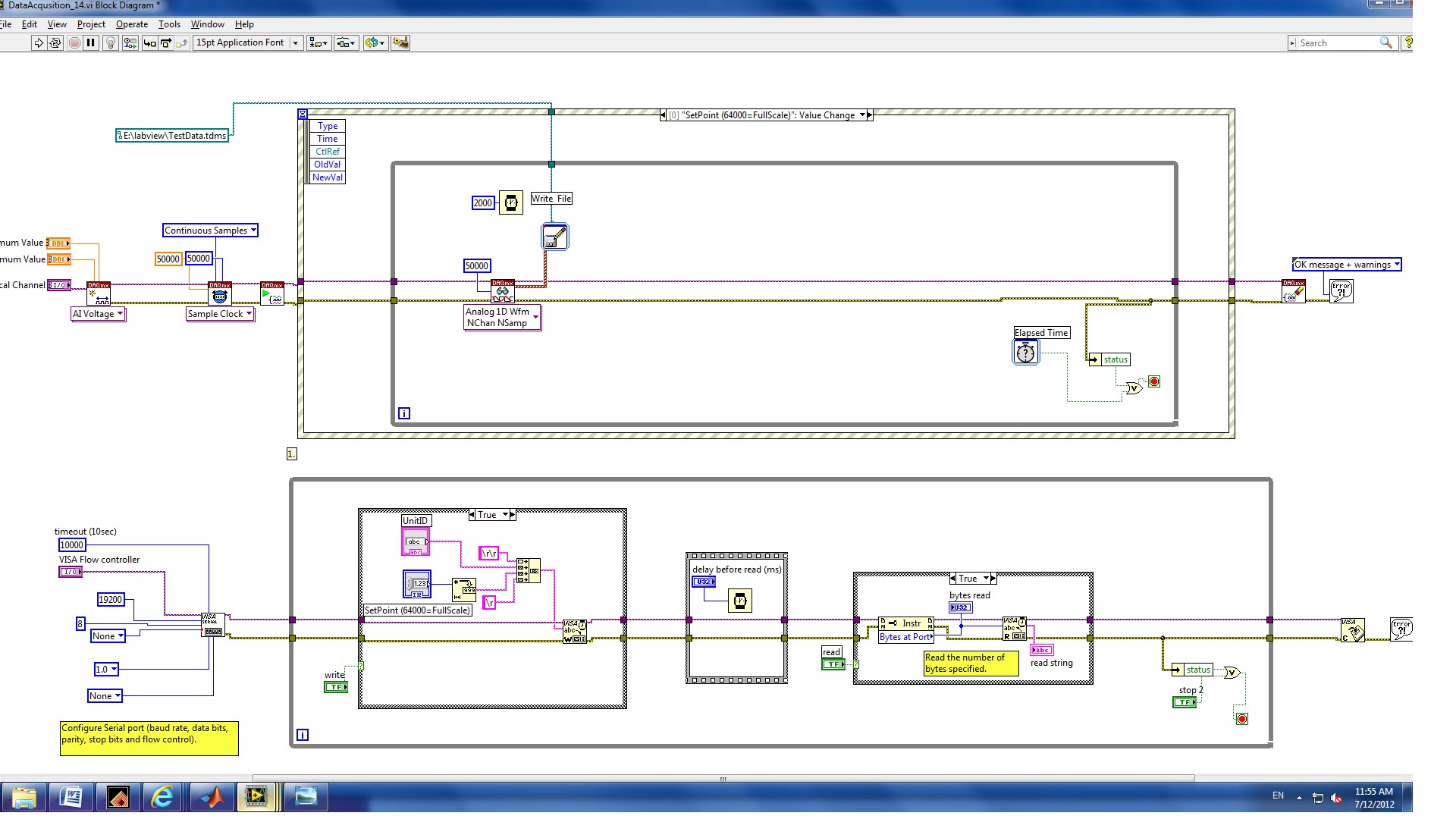
I have a VI with NI9215 and cDAQ-9178 chassis hardware. The function of the VI came out an instruction to RS232 interface and record 1 second of data every time that the set point is changed.
The procedure is
(1) modify the policy to the flow regulator
(2) wait 2 seconds.
(3) record of 4 channels for one second to the sampling frequency of 50 KHz.
At present, the problem is for the first edition of this program, two seconds (rather than) data was saved and corn, the error message 200279.
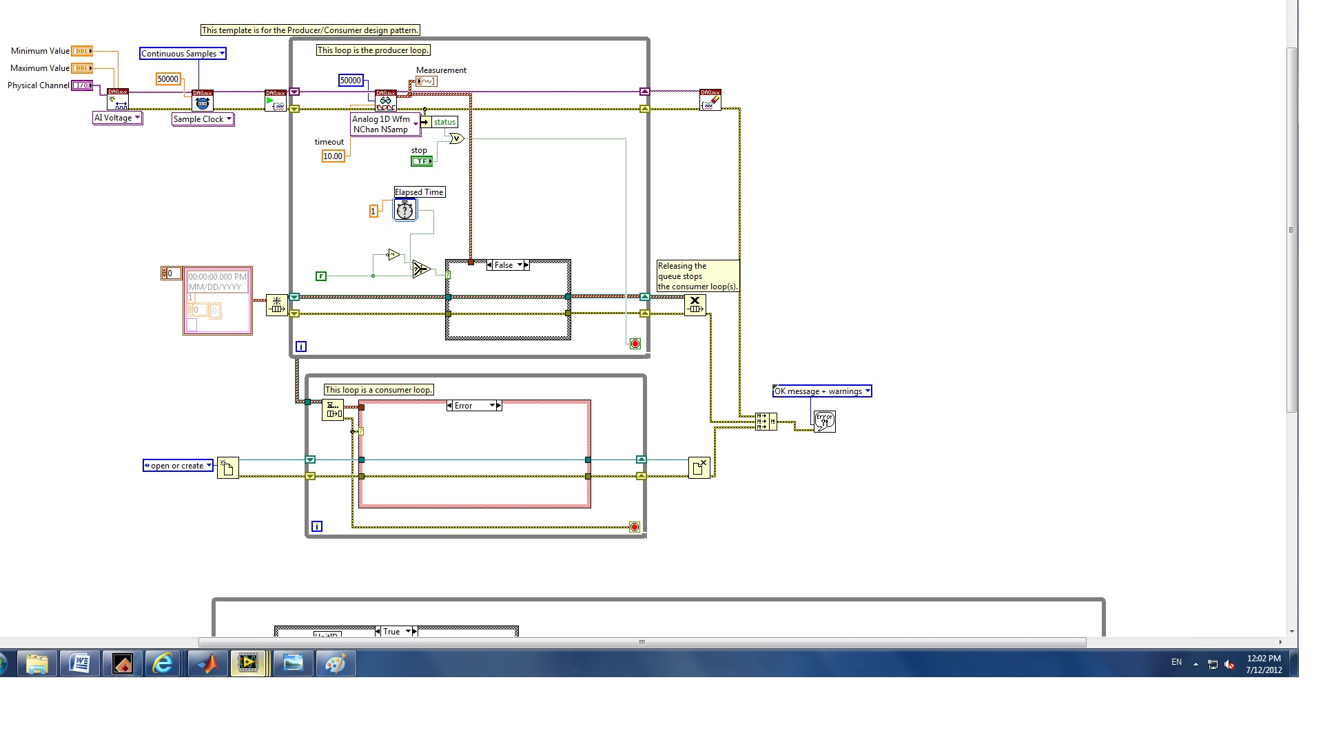
II. I revised for the second edition of the structure of the producer and the consumer who can increase the speed of the buffer.
The question is how to configure the trigger to start the backup of data and limit data save for one second whenever the set point value changes.
(1) which edition is best for my application?
(2) how to trigger the data record?
(3) how to record only a second of data?
I also checked this announcement and the elapsed time seems not to work for this case.
Any help would be greatly appreciated!
Melody
Hello
you have not used properly the nodes property.
1. replace the case structure in the first loop, with DAQmx features, with a structure of the event. Change the event fires for a worth of control of the setpoint change.
Edit: as stated in your first post, use the structure of the event, but put inside the while loop.
2. DO NOT connect error output from the stop command property node. Replace it with a local variable for the stop button.
Try these and let me know.


Maybe you are looking for
-
I need upgrade of Lion but do not have to install the latest version of El Capitan (10.11.6). How can I upgrade 10.11.3 instead?
-
Hi team I followed every food I can find on google, adobe and mozilla support RSS to solve the course adobe flash plugin problem, I have uninstalled and reinstalled more than 8 times now, even tried to install older versions, and it does not work, ha
-
Since I use sync I now duplicate bookmarks, but if I delete a duplicate, it removes the copy and the original, how can I get rid of this second series of bookmarks?
-
Re: How to enable/disable the module BT on Satellite A300?
I have Toshiba Satellite A300 - 1 MM.When I try to connect to my Wi - Fi network NOW I have to ACTIVATE the switch, on the front of my laptop and all works well, but peripheral, Bluetooth is enabled. I would like to disable the Bluetooth and works wi
-
Scrolling touchpad satellite A210 disabled after Windows Vista update
Last week, I did an update of Microsoft Windows. Sine that update I can't the Satellite to recognize its touchpad and the only driver updates work for a standard PS2 Mouse. I can no longer use the bottom and side of the Toshiba touchpad scrolling fea