Model PWM measurement for continuous samples on higher frequencies (100 kHz) with SemiPeriod(HighTime / LowTime)
Hi people,
I have a challenge I'd like to discuss with you and hope to have some ideas and maybe a solution.
I have a systems acquisition (DAQ) Multifunction National Instruments NOR-PCIe-6353 means X-Series!
I would like to generate and measure signals pulse width modulation .
DRIVER:
OUTPUT:
FREQ: 0, 1 Hz - 1 MHz
Duty: 1-99%
Change the setting on the fly
(This works very well and is implemented)
ENTRY:
FREQ: 0.1 Hz - 40 kHz
Duty: 1-99%
Method of measurement: period of semi / ContinuousSamples / AsyncCallback
Here, I have problems I am running only on an Intel Core 2 Duo CPU E8500 @ 3, 16GHz.
And I want to run 2 PWM_IN and PWM_OUT 2
Low frequency work fine!
0.1 Hz - 20 kHz
It is a loopback with
myCounterReader_1.BeginMemoryOptimizedReadMultiSampleDouble (2, myCallback_1, myPWM_IN_1, myPWM_IN_1_Data);
Data = myCounterReader_1.EndMemoryOptimizedReadMultiSampleDouble (ar, on myPWM_IN_1_Data_actualNumberOfSamplesRead);
A higher frequency do not work very well!
20-40 kHz
I get exception Code of State-200279:
Attempted to read samples that are no longer available. The requested sample was already available, but has since been replaced.
Increase in the size of buffer, most frequently the reading of data or by specifying a fixed number of samples to read instead of reading all available samples would correct the problem.
Property: Value of NationalInstruments.DAQmx.DaqStream.ReadRelativeToRequested:
NationalInstruments.DAQmx.ReadRelativeTo.CurrentReadPosition
Property: NationalInstruments.DAQmx.DaqStream.ReadOffsetRequested value: 0
Task name: NI1_PWM_IN_ctr0
State code:-200279
40 kHz, period is 25us = 12, 5 HighTime and 12, 5 LowTime 50% DutyCycle
This means that each 25us I get a reading of 2 samples the HighTime and the LowTime
I charge my task of Max, so here's the Setup (sorry its german):
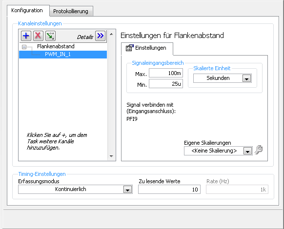
1 can someboby you explain to me what the MemoryOptimized?
2 Zu lesende values means that the size of the buffer 10 is not much but increases the size of the buffer to say 10,000 needing help on
a longer time!
3. playback of data more frequently is not possible because the data are under tension, because it is
4 specify a fixed number of samples I der number is HighTime 2 and LowTime
5. I have does not start and stop the task! Is it better to start and stop the task each time while I still may have a new buffer?
I hope someone has an idea for!
By
Steven
Reading with 50 software we period - bad idea, you will jump impulses. Try to use DAQmx Read Overwrite property, set it to "crush the unread samples" - it will overwrite the impulses without error.
Tags: NI Hardware
Similar Questions
-
Writing data to extend the acquisition of data for the sampling rate high file
These are the tasks that I have to do to take noise measurements:
(1) take continuous data to USB 6281 Office, in a sample of 500 k (50 k samples at a time) rate.
(2) save data continuously for 3 to 6 hours in any file (any format is OK but I need to save in a series of files rather than the single file). I want to start writing again file after every 2 min.
I enclose my VI and pictures of my setup of the task. I can measure and write data to the file continuously for 15 minutes. After that, I see these errors:
(1) acquisition of equipment can't keep up with the software (something like that, also with a proposal to increase the size of the buffer...)
(2) memory is full.
Please help make my VI effective and correct. I suggest to remove him "write in the action file" loop of consumption because it takes a long time to open and close a file in a loop. You can suggest me to open the file outside the loop and write inside the loop. But I want to save my data in the new file, after every 2 min or some samples. If this can be done efficiently without using Scripture in the measurement file then please let me know.
Thank you in advance.
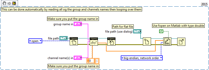
This example here is for a single file and a channel, you should be able to loop over that automatically. The background commentary should be the name of the channel, no group namede the name of the channel in the control.
-
Generate digital waveforms of high frequency
Hi all
I have some problems. Today, I am generating several digital high frequency waves with my DAQ (PCI-6251) card. The duty cycle of the waveform must be adjustable.
The required frequency is 100 kHz.
To do this, I have tried several solutions:
(1) I used counters in the acquisition of data to generate waveforms, and it worked fine. However, I have only two counters. In my application, I need to at least three waveforms with different cyclical report;
(2) I used a 'loop' and structures 'case' in labview to build the model of waveform and then feed them to the digital I/o. However, the problem with this solution is that the frequency of the wave generated cannot be high.
(3) I used a 'digital' generator in Labview to generate waveforms and then feed them to the digital I/o. In this case, the time base is from an external source (200 kHz). However, with this solution, the cycle is not adjustable.
Please give me some advice on how to make these waveforms. Your assistance is appreciated.
OK, so I may be wrong, but after mucking around for a bit, I realized that the regeneration should be automatic - in other words, if you a pattern to the right and then just leave your VI work in a while loop, you will find that the generation is continuous. Discover the correlation dig write metered in the finder for example Labview. You can leverage this as you get the cyclical report you are looking for. You can split the signal down what you write a single period consisting of a series of 0 and 1. In other words, if you want a wave of 100 kHz with a cycle of 20%, you write a pattern of digital waveforms a 1100000000 at the rate of 1 MHz. Using this technique, the resolution of the cycle will be limited by the on-board clock speed (80 MHz = 0.125%).
Let me know if this makes sense - I am unable to reproduce this on my desktop and have never had to do this before.
Cheers, Matt
-
Sampling rate higher for the measurement of precision meter
I have a BNC 6259 M Series DAQ USB. I am currently using the DAQ Assistant to perform simple cash rising measured with the measuring mode single sample on request. I tested my VI with a known square wave with a function generator signal and it clearly lacks a few edges. I think that the solution lies in faster sampling. However, I was not able to understand how to use clocks to set up continuous sampling mode. I tried the forums and I found articles that were close, but not quite exactly the problem I am facing with as (http://forums.ni.com/t5/Digital-I-O/trying-to-use-NI-6251-s-DIO-port-as-input-and-output/m-p/448035#...) or (http://forums.ni.com/t5/Multifunction-DAQ/Using-Counter-of-PCI-6024E-with-Quadrature-Encoder/m-p/984...). Any guidance here would be great.
In fact, the calendar should not have anything to do with the edges being detected. Configuration of a sample clock for a county of just edge task allows you to enjoy deterministically in the account register and has no impact on the edges which can be counted. Also, the analog examples really have nothing to do with what you seem to be asking questions on.
... So it leaves the question unanswered as to why you might miss the edges. Perhaps the following information could shed some light on the question:
1. it is possible that you do not configure the counter exactly as you think you are. Can you post the VI you use? As a point of reference, count digital events shipping example does not use any clock sample timing and just questioned the value of the register count with a software loop, but the meter should not miss all this edge on the input source. There are examples that are timed by the material available as well, but this is not necessary, unless you need a constant specified dt between your counter samples. To use the examples of the timed sample, you will need to generate a clock of either another subsystem on the map or use an external clock.
2. assuming that the configuration of the counter is not the issue, there may be a problem with the method that you use to determine if you are away from the edges. How do you know that you are away from the edges? The function generator produces only a finite pulse amount? You start the meter before start out impulses?
3. If the two points above do not raise red flags, it seems likely that the meter is registered just not some of the impulses of your FGEN. Can I assume that the output of the FGEN is 0 - 5V TTL? What is its frequency and duty cycle? The maximum external source for the meter on the M-series products: DAQ (like the 6259) is specced at 20 MHz, but this depends on a clean signal with good connections. At frequencies above it, the bandwidth of the front-end of the PFI lines becomes limiting. If you have an available specification document for your FGEN I'd like to be able to see it.
I hope this gets you throw on the right track to solve the problem - impatience comes back with more information.
Best regards
-
given high-frequency sampling one at a time
Hello
I'm using LabView 2011 for resistance measurements. The express vi DAQ assistant is placed in a while loop and it acquires 1 sample (on request).
Each sample is acquired, it is compared to a set point. If the resistance value is greater than the set value, a task is executed. If this is not the case, no action is taken.
Now, I would like to increase the frequency of acquisition of say 5 kHz. As before, I wish the DAQ to give each value because it is acquired and compare it with the desired value. However, only one point acquistion is limited by the speed of the while loop (which does not exceed a few Hz per second when I use the software-timer.) If I use 'continuous samples' at 5 kHz, data acquisition does not give these samples one at a time. It seems to acquire until the buffer is full and then released several samples at a time. It is therefore impossible to compare with the set value.
Is it possible to get data at a high frequency and do compare to the set value, one at a time?
The code is simple enough to do this.
But the problem, it all comes down to how fast all of the other code in the loop takes to run.
The first problem is that you use the DAQ Assistant, which provides a lot of extra load in the loop, especially if you don't set it up properly. (And we can't say because no code is set to look at us.
You should try a real code DAQmx where launch you acquisition continuous samples before the loop, acquire exactly 1 sample in the loop. Then close the DAQmx task once the loop ends. See if keeps.
Why do you need to do this? Note that all instant Windows might decide to fly a second or two and go and do something else like a virus check. If you need at that moment (how exactly do you need that?), then Windows is not the right system for this run.
-
Why can I not make a continuous sampling of port 0 on USB 6216?
I have a USB-6216 of NOR. I try to capture digital signals using port 0. However, the only way that I can function is samples on request. If I select N samples or continuous sampling, I get the following in the DAQ SignalExpress Wizard error message both Labview 2011. What I'm not doing correctly?
Error-200077 occurred to the DAQ Assistant
Possible reasons:
Requested value is not supported for this property value. The value of the property may be invalid because it is in conflict with another property.
Property: SampTimingType

Requested value: sample clock

You can select: on request
The 6216 not having a sample for the e/s digital clock as you can see from reading the specification, every time you try to use one, you will get this error message. Thus, in LabVIEW, whenever you want to do a reading, you must call a single value DAQmx Read mode single sample (or the DAQ Assistant, configured the same way). How many samples per second you take is going to be highly variable due to windows being nondeterministic.
-
acquisition of data with different sampling rates high
I have a few questions on the use of the OMB-DAQ-3005 with different sampling rates high.
For our application, we have 8 analog inputs. Which two are a quick response and should be sampled frequently. We have an encoder quadrature (CPR 1000 running at 1800 rpm). We plan to sample X 4 encoder. For the analog inputs for the quick response, we want to trigger a sample of each pulse or each a few pulses, thus creating a timestamp with the position of the encoder with respect to position index as well as two fast analog inputs. We have data correlating the analog inputs with the position of the encoder. Other analog inputs, we want to measure relatively slowly (for example once every 5 dry or similar).
How can I go on the configuration of the two (or more) sampling rates different wherein I can taste entered at different frequencies? Also, is there a way to reset the encoder count after outbreak of the index as I have the position of the encoder with respect to the index?
Maybe you'll find someone here who uses the OMB-DAQ-3005, but this forum is really more designed for LabVIEW programming issues.
I've never used the OMB-DAQ-3005, but out of curiosity, I took a glance at the Manual of OMB-DAQ-3005. The answer to both your questions are:
1. you cannot run a hardware DQA Multiplex (like this one) at independent rates by channel.
2. the OMB-DAQ-3005 supports an Index Z feature to reset the counter - look for documentation on how to configure any software interface you are using. If you get stuck, you can try to discover media appropriate for instrument channel.
Best regards
-
Continuous sampling method get unreasonable values
Here to measure the amplitude of a signal as Attaché of the 'Ori.jpg' file, if you use the method of samples N (1 k samples, rate of 239kHz) for the acquisition of data, the result was perfect in the file '1k_N.jpg '. But the speed was too slow.
Although the method of sampling performed much more quickly, continuous values were not usable. As files "1k_continuous.jpg". Do not know what is causing these outliers, and he only appeared occasionally. The 10.5537 should be the maxmum reading value of NI 6361.
BTW, is - this impossible to accelerate the sampling method N? Even tried 20 samples instead of 1000, the loop still cost of similar duration. Data acquisition was not stopped in each loop.
Helps decrease the time of N sampling or taking good readings from continuous sampling method are greatly appreciated.
PEM
In the version N-samples the DAQ Assistant acquires only 200 samples whenever it is called and it returns oll of them. In the continuous version samples sample are acquired in the 59000 per second, they are returned to the main program or read or not. Yes, at a rate of 20 ms per iteration about loop 900 new samples are acquired than read at each iteration.
When an error occurs the DAQ Assistant, stops the task and Unreserves it. The next time the loop runs through the DAQ hardware to reconfigure. I have no way of knowing with certainty, but it is possible that some false values enter the buffer during the shutdown process / reconfigure.
Lynn
-
Units of measure for network made and received
Hello
Looking at some data in the data base of CB, the units of measure for the resource type 6 (network) received and transmitted is labeled as "GB / h. Some of the sample values by looking at daily performance stats I see values such as 112 629 and 111 134 to the following sample. So should I interpret this value so that they would have sent / / received 112 629 gigabytes for this time if the use has been constant during this time? It's really high for what was actually happening. Is it not really Kb / hour?
Bill
Hello
Internally, vCenter chargeback divides the values of the sample by the conversion factor to get to real values. For the resource type 6 (network received and transmitted) the values of samples in the CB_VC_PERFORMANCE_STAT table are saved in Kbps and when calculating costs are converted to GB / hour by dividing the value of the sample by 291.271 ((1024*1024) /(60*60) = 291.271). In your case, the real GB by time values would be of the GB/hour (112 629 / 291.271) and (111 134 / 291.271) GB/hour.You can find the conversion factors in another table CB_RESOURCE_VC_COUNTER_DETAIL.-Amrainder -
Effectively change the continuous sample mode sample mode finished
9188 chassis, modules (HAVE them), 9 of Labview
I want to acquire continually (and display) given at a fast rate to date, and then when a 'trigger arms' State is detected, the switch to finished hardware, triggered task with pre-trigger samples with a minimum loss of perceived as update rate.
What is the best way to do
Thank you
Collin
I started my answer a long time ago while waiting for a reboot and am just finally getting back to it. I see that you got another another answer in the meantime. On the outbreak of reference, here is another link that might help some: Acq suite w / Ref Trig
I did have not tinkered with reference trigger a lot, so not sure what is meant in the link above about the task being an acquisition over 'the end'. Maybe the task continues to fill the buffer just before there about to overwrite the first sample of pre-trigger?
In any case, my original thought the whole thing was on another track. If the trigger Ref works for you, it'll be easier. But if Ref trigger causes the acquisition of stop * and * you really need to keep it going permanently, then consider the things below:
-------------------------------------------------------------------------------------------
Passage of the continuous sampling done will require the judgment and the reprogramming of your task, and you will have a 'blind spot' of data loss, while what is happening.
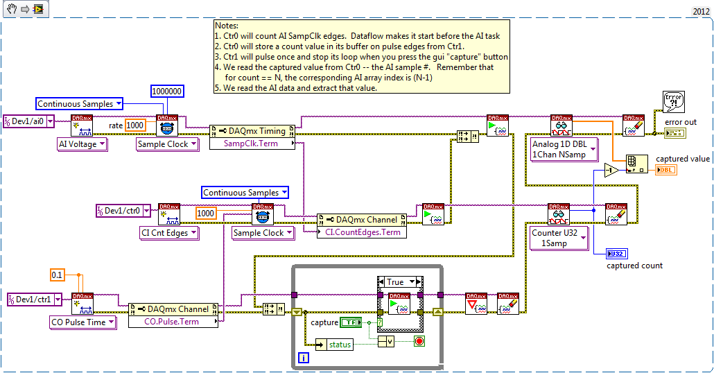
An approach that I think is to stick to a sampling WAS continuous, but also set up a counter task that can count it HAVE examples of clock and capture on the trigger signal. The captured value of count will be HAVE it taste # when the trigger has occurred, and then easily post-process you your data HAVE to find the subset that represents your data before and after the desired trigger.
Here is an excerpt of what I mean 2012:
-Kevin P
-
Considerations of sample calendar high rates (~1MS/s)
Hi all
My experience with Labview is quite limited, and so far I have mostly editing and debugging code which was bequeathed to me. I use USB DAQ to taste to 10 samples/second card and were not too concerned with the precise timing. I am interested in a new application of hardware and software of NOR and identified the USB-6343 map like the one to use (900 ksps / s 500kS/s and input, output). The plan is to generate an accurate output signal (amplitude and timing accuracy) which is a bit facings on the input signal. I don't plan to write the log data to a file at that rate, just to capture, process and output.
It is relatively simple to be sampled and transmission of analog signals at these high frequencies of sampling? Currently I use just loops timed precisely to the millisecond, but that would require a precision microsecond timing. Is this something that is pretty standard to achieve or are these frequencies of sampling carried out a totally different way? Can anyone provide links to point me in the right dirrection?
I'm sorry if this question has already been asked, but I hope that it is generic enough to not be a burden. It is a project that I take in my spare time, so I am just in the things of plan which includes determine how difficult side things software is going to be.
Thank you.
-A
The acquisition DAQ clocks will give you the best time you can get. If recover you the data in the form of wave, t0 represents the start time and dt, the time interval between samples. If you've read continuously, all samples of data are synchronized compared to t0. The accuracy of dt is equal to the precision of the oscillator of time base on the DAQ hardware, usually +/-100 ppm.
I don't remember the clock on the USB-6343 frequency, but many devices use 80 MHz. You won't get exactly 900 kHz to 80 MHz source, because this isn't a full report. 80 MHz / 900 kHz = 88.888...
The use of millisecond clock is called avoiding the and is fast enough, nor free from jitter to do something like what you have in mind.
Lynn
-
acquisition of continuous sample with multiple channels
Hello! Please tell me what I'm doing wrong here, I'm confused about how the acquisition of continuous sample with several channels (using NI USB-6215 boxes).
Following code is python code, but I don't know who confuse you
 (and it's only a part of my code in order to not try, it won't work
buffer_size = 2000 #samples to read
sampling_rate_hz = 20000
channels = "Dev1/ai0 ai1/Dev1" #this can be a string or a large number...CHK (nidaq. DAQmxCreateTask ("", ctypes.byref (taskHandle)))
CHK (nidaq. DAQmxCreateAIVoltageChan (taskHandle, channels,"", DAQmx_Val_Cfg_Default, float64(-10.0), float64 (10.0), DAQmx_Val_Volts, None "))
CHK (nidaq. DAQmxCfgSampClkTiming (taskHandle,"", float64 (sampling_rate_hz), DAQmx_Val_Rising, DAQmx_Val_ContSamps, uInt64 (buffer_size) "))
CHK (nidaq. DAQmxRegisterEveryNSamplesEvent (taskHandle, DAQmx_Val_Acquired_Into_Buffer, uInt32 (1000), uInt32 (0), EveryNCallback_func, None))
CHK (nidaq. DAQmxRegisterDoneEvent (taskHandle, uInt32 (0), DoneCallback_func, None))
the callback function #and
def py_EveryNCallback_func (self, taskHandle, event_type, nSamples):
data = numpy.zeros ((self.channel_amount,buffer_size,), dtype = numpy.float64)
read = int32()
CHK (nidaq. DAQmxReadAnalogF64 (taskHandle, buffer_size, float64 (10.0), DAQmx_Val_GroupByScanNumber, data.ctypes.data, buffer_size * number_of_channels, ctypes.byref (read), None))With only one channel, everything's fine, and tension diagram looks like this:

buffer_size = 2000, sampling_rate_hz = 20000
But if I use two channels, voltage diagram looks like this

buffer_size = 2000, sampling_rate_hz = 20000
It looks like the sampling rate is higher or there are fewer values?, but with two channels with the results table is 2000 * 2 long and with a single result is 2000 * 1 long is not smaller
most of the settings important (?) in my code:
DAQmxCfgSampClkTiming "float64 rate": 20000 (sampling_rate_hz)
'UInt64 sampsPerChanToAcquire' DAQmxCfgSampClkTiming: 2000 (buffer_size)
DAQmxRegisterEveryNSamplesEvent "uInt32 nSamples": 1000 (?)
'Int32 numSampsPerChan' DAQmxReadAnalogF64: 2000 (buffer_size)
DAQmxReadAnalogF64 "float64 [] readArray": [[buffer_size] * number_of_channels]
'UInt32 arraySizeInSamps' DAQmxReadAnalogF64: buffer_size * number_of_channelsas you can see nSamples is a big question mark, but the problem still exists if I set variable buffer_size y (2000)
Hi Dazzler,
It is not a multi-channel example that ships with the driver, but after a quick look at the code that you use in your third post, everything seems to be configured correctly. The only thing I was thing I got a question about your plots. Looks like you draw each time the same number of points. If you draw just the table of data directly from the playback feature, you need to draw (buffer_size * number_of_channels) number of channels since the data returned is as an interlaced array. You can also choose to deinterleave samples. More information about this lie in the NOR-DAQmx C reference help, which is installed with the NOR-DAQmx driver.
Kind regards
Kent
Technical sales engineer
-
choice of the model of design for data acquisition system
Hi all
I have a problem on the selection of the model design / architecture for a data acquisition system.
Here are the details of the desired system:
There are data acquisition hardware and I need to use by looking at the settings on the user interface.
the period of data acquisition, channel list to analyze must be selected on the user interface. In addition, there are many interactions with the user interface. for example if the user selects a channel to add scanlist, I need to activate and make it visible to others on the user interface.
When the user completes the channel selection, then he will press the button to start the data acquisition. Then, I also need to show the values scanned on a graph in real time and save them in a txt file.
I know that I can not use producer consumer model here. because the data acquisition loop should wait for the settings to scan channels. and it works on a given period by the user. If the loop of user interface makes higher then loop (loop data acquisition) of consumption. This means that queue will be bigger, larger. If I use notifier this will be some data loss comes from the user interface.
y at - it an idea about it? is there any model of design suitable for this case?
Thanks in advance
Best regards
Veli BAYAR
Software for embedded systems and hardware engineer
Veli,
I recommend the model producer/consumer with some modifications.
You might need three loops. I can't tell for sure from your brief description.
The loop of the User Interface responds to the user for configuration entries and start/stop of acquisition. The parameters and commands are passed to the Data Acquisition loop via a queue. In this loop is a machine States that slowed, Configuration, Acquisition and stop States (and perhaps others). The data is sent to the processing loop through another line. The processing loop performs any data processing, displays the data from the user, and records to file. A registrant can be used to send the Stop command or stop the loop of the UI for other loops. If the amount of treatment is minimal and the time of writing files are not too long, the functions of processing loop might be able to happen in the case of the UI loop timeout structure of the event. This makes things a little easier, but is not as flexible when changes need to be made.
I'm not sure that there is a type of design for this exact configuration, but it is essentially a combination of the models Design of producer/consumer (data) and producer/consumer (events).
Lynn
-
Which macbook model is good for daily stock trading?
Which macbook model is good for daily stock trading?
None of them are suitable.
-
TM is not only sufficient capacity for continuous backup
Time Machine is not sufficient capacity for continuous backup, I examine in order to free up space in the time Capsule, but I like to keep a complete backup/restore source for my MBP.
If I could keep the backup history to start now I don't like to take some backup stories are duplicated or doubled. At least, I could recover my MBP if replacement of HDD, new MBP migration or data recovery after the MBP were repaired by Apple Store Home.
How can I delete the history of backups to free up some space and maintained all the data while restore or recover any catering MBP?
Identical to this thread, I just answer.
Do not attempt to remove the files... He eventually didn't save almost no space and you're more likely to corrupt the entire backup.
Just the archives outside the TC, wipe it and start over.
Maybe you are looking for
-
I was watching a movie on a site that I subscribe to and a screen came to ask if I wanted to add a filter. I clicked Add Filter. Now my Flash Player is not compatible on Mozila Firefox but not Internet Explorer
-
How to print a document with the comments appear?
I try to print a document Pages and I want the comments to be visible. They disappear in the printing process. Thanks for any suggestions!
-
Hello everyone, Can someone please help me in sort of a 2D array. Here's the requirement there will be some groups and each group is composed of 'x' number of items. The user enters only the elements but in a zig zag order. And the short program of s
-
Wireless adapter does not work.
Original title: wireless I install win7 in my fujitsu siemens AMILO Li 1718 model system, all the drivers are installed but I have problem with my wireless, wireless is not see the amything all available wireless driver is installed courrently can so
-
Start and End DateTime calculations
Dear allI have 3 fields start time, end time and hours. I want that if I give hours then the start time should be filled in with the current date and time and end time must be calculated accordingly. Suppose I have hours = 1 then start time should be