Elliptical instead of circular gauges gauges
I use LV2009 on a Pro WIN_XP machine.
The monitor is a Dell 17 "LCD type running at a resolution of 1024 x 768.
Whenever I try to put a gauge on FP, it always turns out elliptical. (Extended width) I tried their utmost to make the round template, but have failed.
In properties I tcicked the window since for different resolutions 'maintain '. Indeed, the VI that I developed in this PC displays correctly when I open it in my laptop for 1280 x 800.
Is this a Dell monitor problem? Advice to show my circular gauges rather like eggs?
Tags: NI Software
Similar Questions
-
Circular graphic help of gauge
Hi all:
I'm looking for help on creating chart circular gauge.
The model foglight opens when you click on that gauge circular, that's exactly what I'm looking for.
I have a metric data against 'count' I want to draw it. It can vary in hundreds of each sampling - like 350,180,470,790,230, etc...
I would like to draw as a circular gauge that has say (static) as long as the maximum threshold of 1000 and 0 as the minimum threshold. The maximum if possible can be dynamic based on the data collected during the specified time interval. The tick at one point must be the current value sampled in the gauge.
Now when I do the definition is what I can specify the metric. I played a little 'MinMax Show', 'Threshold to show' etc. but all it gives me is a graph that has the tick at the end maximum say 420 for this particular sample.
I was looking for some Foglight UI viewpoints for a few references but did not find any.
Please can someone understand me a little better on the way to draw it or show me an example that I can use. I read the doc page, but I'm not anywhere with her.
Any help is greatly appreciated.
Thank you very much!
APO - Barro
Hi Baro,
The function that I used is very simple: it returns the name of the parent object of the metric:
The definition of this function is:
return metric.getContainer () .getName)
Kind regards
Brian Wheeldon
-
Measures of constraints with the NI 9219
Hi all
I join this forum and I need bit of advise on measurement of deformation using NI 9219 with lab view.
I followed the procedure and settings to configure a virtual channel to strain under global virtual channel of NI DAQ mx.
I need some clarification on strain gauge measures:
1. If I use 1 quarter bridge configuration should I NI 9219 completion resistors?
2.i have ordered strain gauges, but I can imitate the calculations of strain with labview gauge using a variable resistor instead of active Gages? as I understand, it's strain gauges to change resistance when the force is applied.based on this notion if I use a variable resistor on one leg of wheatstone bridge and plot the data? all I want is to play with lab view until I get the real strain gauges. (will take a week to get deleivered)
3. affecting the internal Vex I think that I will not need to apply any voltage to the terminals of the bridge as the strain of installation window.i would just need to connect to the ends of the stone bridge of wheat to the PIN number 3 and 5 in the comment of 9129.please OR who...
I have to really thank and appreciate all of you for taking the time and reading/commneting on my post.
Kind regards
Ali
Hi Engr_tech,
9219 a resistance integrated half-bridge completion, but for quarter-bridge measures, it must rely on resistance measurements 2 son. It does not support the measures of quarter 3-wire bridge. I'm not familiar with the help of a variable resistor instead an active gauge so I can't comment on that. Looks like your #3 idea would work, although I'm not 100% certain. It will be unsupported, but it could work.
-
Looking for suggestions on how to implement a dashboard bulb
Finally, we confess allowed to make the jump from Apex 3.2, 4.2. I have a dashboard that has been done in 3.2 I want to redo from scratch. This is a page of dashboard with many parameters "bulb". Here is a sample of one:

I was thinking about using the solution of Camembert and just scaling down to this size and making the value appears on the top. But I couldn't figure out how to get to work.
Here are some of my requirements.
- I prefer not to use Flash. That's how it is currently underway on the installation of 3.2 and it seems to have a lot of questions. HTML5 sounds like it would be more stable (correct me if I'm wrong)
- There is no budget to purchase additional software, so I need to make it work with Anychart solution or a free plug-in
- I need the color either dynamics, 0 means it would be green > 0 it would be red in most of the cases, but the color is what KPI-based engine array or measurement is displayed.
- He has to work on a variety of possibly include mobile screens.
Thanks for your help in advance!
It always seems to be a great resource!
TC-army wrote:
Jeff (and others)
I really like this type of solution, but I do not think that it would be suitable for my specific case. I'll have to replace what is there because he died in IE 11 unless it is in compatibility mode and we have to work all the code * without * mode of compatibility before Dec. 31.
Why it would not fit your needs? A solution based on HTML and CSS standards is the safest option in terms of compatibility ahead and back (provided that it degrades gracefully in older browsers).
I have created an example of this type of solution on page 586, using standard reports with a model of custom report to render data, CSS to control the presentation and dynamic actions to respond to the intervention of the user and update the display. I'm not clear on exactly how to query the data and some minor questions of presentation. As regards the presentation and user interaction is this position from the right direction?
Looks and works OK in Safari on OS X and iOS. How is it in IE11 (I don't have access to it)? IE8 and other older browsers that do not support borders and degraded background curves get the square buttons with flat bottom instead of circular bulbs shaded colors.
Users are very used to a certain page layout. Top is light bulbs of group and the central area is pierced with bulbs. So the albums turn green, yellow or red are based on all KPI bulbs in this group. If all the bulbs in this group are green, then the Group bulb is green. If even one in the group is red while the Group bulb is red. And the bulbs of the group have numbers on them. The bottom area breaks out the average bulb by location in a bar chart.
Data on apex.oracle.com seem not to be a behavior like this, and it is not enough to explore all the options for layout and presentation and questions. It would help if it was consistent and not there enough to cover all the possibilities.
-
I really don't care much for the use of the view of the office more and want to do everything that the sight of tiles Windows 8.1. Is there a way to see the amount of battery life I left without leaving the desktop view to see in the taskbar?
Hi @8dakota8,.
Thank you for posting. I read your post, and I understand you want to make the battery indicator to display on the start screen. I'm happy to help you in this.
Here is that a document can help:
How to add a Windows 8 start screen battery indicator
To say thank you, click on the "thumbs-up". Accept the post as a solution, so problem solved, so that other people that you have the same problem can see.
Kind regards
-
Hi all
Here is the set of data that I am facing problem with the gauge display:
Gravity: S1
SLA met: 0%
Not satisfied with the SLA: 100%
I put the range in size only - green: 0 to SLA met
Red: SLA met at 100.
This setting is ideally the dial must be filled with red and the pointer must be 0%, in my picture of the outside of the dial is filled with Red and inner circle is fill up with Green.
For all other values of the ALS, it displays correct percent of green and red. Any suggestions why this is going on 0%.
Please provide your inputs.
Kind regards
SwatiHow and where you set the conditions? You can try the configuration into something like 0.01% instead of 0%?
-
It seems that samples of Degrafa gauge do not work in the latest download of TDF. I assume it is because Degrafa moves to an extension .org instead of a .com extension.
This could be corrected? I was really hoping to see these for a customer proposal that I would do
Thank you!
Rob
These are now corrected.
Thank you!
Greg
-
I want to create a preloader with a Gauge that shrinks from left to right. My Gauge is a white box. I want to discover the layer behind him reveal actually more of an image while the swf file is responsible. My code (works if I try to 'push' the Gauge below). I tried to use a sign less in reverse mathematics, but I couldn't figure out where to put. In which case it is important, I have my film set in place with the anchor on the right side (since this is the point I want to remain fixed).
Thanks in advance.
Action script to grow the Gauge (how can I shrink instead?):
bytes_loaded = Math.round (this.getBytesLoaded ());
bytes_total = Math.round (this.getBytesTotal ());
getPercent = bytes_loaded/bytes_total;
this.loadBar._width = getPercent * (100);
this.loadText = Math.round(getPercent*100) + '% ';
If (bytes_loaded, bytes_total)) {}
this.gotoAndPlay (5);
}The easiest way to find out is to use only the preloader as usual - code so
It goes from 0-100 and set the _xscale of clip a bar that's a layer mask for
your image. If you really want to see the bar shrink from left to right then
make your bar have points on the right edge of its registration. Then, you can
again use normal code that goes from 0 to 100 and the helm xscale
100 - per cent.--
Dave-
Developer leader
http://www.blurredistinction.com
Adobe Community Expert
http://www.Adobe.com/communities/experts/ -
ADF 11
Hello
I have a table where each row should represent 1 gauge.
The row contains a column for the maximum value, the current value, threshold 1 and threshold 2.
If I drag and move the data from the table of control on a page and create a simple gauge in the gauge data is correct but that a single gauge appears for the first line of the table instead of a caliber per table row.
A set of gauge seems to be for when all the lines share the same thresholds which is not my case.
How can I display each line of the table as a gauge on the same page.
Concerning
PaulYou can use the existing table and add a gauge inside of an af:column by adding the new column to the table.
I don't know how you can generate n number of gauges outside the table (unless you use tags forEach or iterator)Jean Lou
-
11g: how to disable the ToolTip for gauge?
Hello
DVT:graph and dvt: gauge (type = LED) displays a ToolTip by default when you move the mouse over the series or leads.
With dvt:graph you can set the property markertooltiptype to "MTT_NONE" in order to avoid this default ToolTip.
For dvt: gauge, I can't find such a possibility.
How to disable the default ToolTip for dvt: gauge too?
Jdev 11.1.1.0.2
concerning
PeterHi Peter,.
For a gauge, the best way to turn off the ToolTips is to use the attribute renderImagemap with imageFormat = "PNG". For example:
If instead, you decide to customize the ToolTips of the gauge, you can use the alt attribute to shapeAttributes (without the renderImagemap = 'false'):
Hope this helps,
Hugh -
gauge the battery to the boot screen and battery on report menu conflicting Details about the level of the battery. The gauge from the battery to the Starter incorrectly displays the low battery level that prevent the start of the battery. This happens on macbook pro retina 13 inches
When I try to startup macbook pro retina in battery mode, it will fail to start showing low battery level and an indicator to recharge the battery. It does not start on battery. When I then connect via the power cable at startup (and check the battery level), monitor of battery in the menu bar indicates that the battery is charged to the top.
It gets really frustrating and remove my ability to use the macbook pro retina as a truly portable device...
Appreciate any help on this
Have you tried resetting the SMC? Reset the management system (SCM) controller on your Mac - Apple Support
-
Gauge Power Manager: An error occurred when loading Resource Dll
Just installed windows 10. A dialog window opens immediately after the opening session, saying: gauge of Power Manager: "an error occurred loading resource dll. Power Manager pilot was updated using the System Update and Windows Update. Windows seems to work very well after closing the dialog box.
Event log:
The failing application name: rundll32.exe_PWMTR64V.dll, version: 10.0.10240.16384, time stamp: 0x559f39d6
The failed module name: IMM32.dll_unloaded, version: 10.0.10240.16384, time stamp: 0x559f3b64
Exception code: 0xc000041d
Offset: 0x0000000000004c70
ID of the process failed: 0x17bc
Start time of application vulnerabilities: 0x01d0cc1e64ae9c62
The failing application path: C:\WINDOWS\system32\rundll32.exe
Path of the failing module: IMM32.dll
Report ID: dc5d2634-1815-4621-9b48-fdd9d21c8ba8
Faulting full name of the package:
ID of the failed package-parent application:
Solved. The error comes from the task by Lenovo power parameters. By disabling the task in the Task Scheduler, the error disappeared.
This does not affect the function of parameters of Lenovo, just put a little slow to load power information.
-
What is the small black gauge at the top left of the desktop?
 What is the small black gauge at the top left of the desktop? I just got my 10 Omni and put in place today. The screen (office) has this stupid black bar (gauge) on what reads 100. I can't move, close or to understand what it does. Can someone help?
Thank you... sometimes we old guys are a little slower to learn new things
FayetteTerry
I spotted your request when it was 1st posted, but I have not experienced the 'phenomenon' myself so I waited for someone who had to post a fix - might save you a few troubleshooting steps...
If you have already found a solution, update your original post could help direct others to this solution in the future. On the other hand, we can proceed to try a few things to narrow down what is causing this burning "black beast" on the screen of your Tablet:
Right of sending, no matter the cause - just shut down and then restart your tablet can correct the problem. If the bar persists after that, you can check via the Task Manager to identify a suspect probably under Startup items. Your description suggests a battery gadget or an application that uses the built-in microphone shows the sensitivity of the MIC's setting - possibly Skype or other software 'social media '.
Please update this thread with your status current re. This issue...
-
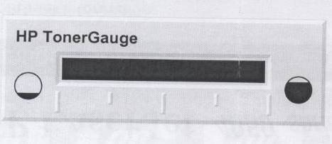
When I tried checking remaining toner, what follows has shown, that tells me nothing?
Help.
Thank you
oldtrout - arsaidh-Brack
GUM BI LEAT SI\TH
Today is perhaps the happiest day of your life and
succeeding every day be even better.
May I always be the kind of person
My dog thinks I'mHi oldtrout,.
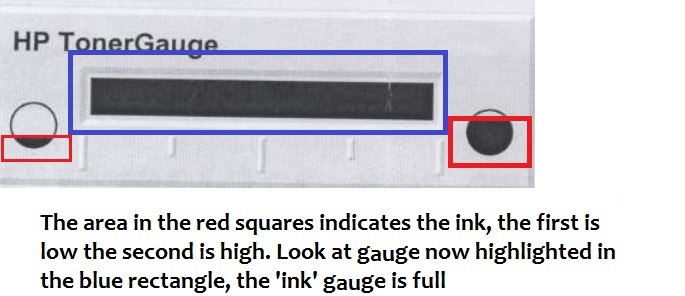
Although I don't know what printer you have, or where you find this gauge of toner, I suspect the image that the toner is full.
I hope that answers your request.
-
Negative results with strain gauges
When I run my VI the results are always negative. I use the NI9237 with the NI9945. I wired my installation as one quarter bridge. There are three wires from the strain gauge. I went on the wires and I think it's okay / characteristics of NEITHER. Is there something in the MAX that I should be looking. Not sure why the values are negative.
Thank you
Harry Stone
Hi Harry,.
There are a few things I want to clarify:
-Traction deformation is positive and compression deformation is negative, what is described a high level in the tutorial below.
Strain with gauges
http://zone.NI.com/DevZone/CDA/tut/p/ID/3642As strain compression is negative, you would see negative within MAX results if your strain gauge knows any compression. Please keep in mind that a shift can be associated with each transducer, that's why some sensors use a calibration certificate. It is produced by the manufacturer and is provided with the sensor as is the specific sensor. The sensor goes through a testing process to determine its actual response compared to the ideal. In this case, a scale of table can be created to include these values.
How to do a custom able scale & Automation Explorer (MAX)?
http://digital.NI.com/public.nsf/allkb/3F6558112FD2C776862575B5004F7F87?OpenDocumentNot all manufacturers of sensors provide a calibration certificate. Or you can create your own table by placing known quantities of pressure, force, etc. on the sensor and map it to the corresponding voltage, or you can create a linear scale in MAX adjusting the intercept (b) the value necessary to remove any compensation.
You use the NI 9237 that compensated supports deletion. A null offset is executed with the sensor fixed without load placed on the sensor. Actually, a measurement of voltage is taken and this value is subtracted off the coast of each subsequent measure therefore removing the start offset. This takes up space you creating a linear scale and in doing so manually.
The two links below show how to use a custom scale created in MAX in LabVIEW, as well as coding the custom in LabVIEW scale to remove the dependency of MAX.
Acquisition of DAQmx with custom scale
http://decibel.NI.com/content/docs/doc-3706Create a linear scale customized for each channel AI in LabVIEW using DAQmx
http://decibel.NI.com/content/docs/doc-11136I recommend using a task sequence. Input parameters for the information about your strain gauge needed to perform the conversions of strain. There is an example of a measure of deformation in the example Finder LabVIEW (* open LabVIEW * help > find examples) designed specifically for the NI9237 that incorporate deleting the offset and shunt calibration devices. If you do not have external wires connected for calibrating shunt such as cited in this document , you will receive an error. Here is an explanation from the NI-DAQmx help Shunt calibration (start > all programs > National Instruments > NOR-DAQ > NOR-DAQmx help) to help better explain this feature.
Shunt calibration (adjustment of Gain)
You can check the output of a measurement system based on a bridge by comparing the measured output bridge with a calculated value if the physical load on the sensor is known. NOR-DAQmx can then use the difference (if any) between calculated and measured values as a factor of adjustment of gain for each measure. You can simulate the application of a load at the bridge by connecting a significant resistance in parallel with the bridge. This resistance, known as a shunt resistance, compensates for the voltage from zero of the bridge. Because the value of the shunt resistance is known, you can calculate the physical load corresponding to the voltage drop of the resistance.Use the Shunt calibration perform the Assistant DAQ or DAQmx VI/function to perform a calibration shunt, which defines the the gain setting for a virtual channel. NOR-DAQmx then uses this adjustment of gain when you descale readings from the bridge. Some National Instruments products are internal resistance.
This may seem like information overload, but I wanted to provide you with a detailed explanation of your understanding, in addition to immediate responses. As a logbook, I recommend that you use the 9237 strain example and use the removal compensation. Negative values are expected for compression and positive for blood. The handy Guide below gives an excellent overview of the strain gauges, which also includes a video.
Measurements with strain strain gauges: practical Guide
http://zone.NI.com/DevZone/CDA/tut/p/ID/7130Hope this helps!

Maybe you are looking for
-
Remove cover from closing/screen on my Satellite 1110-Z14
My Toshiba Satellite 1110 - portable Z14 has developed a fault which means he keepscut to leave a blank screen. If I open and close quickly, he returns to everything and then goes again. It is not cost-effective to repair it and I connected another m
-
allocation of an array of 2d in labVIEW and move to the DLL function to obtain data
Hi all! I searched a lot about this, but one cannot find any solution. Please find attached the vi that I try to get a unit of 32 channels data, 100000 samples per channel with 14-bit resolution. And please also find enclosed the header for my dll fi
-
My 3070 and said that he can´t print! Same IP address on the computer and the printer. What can I do?
-
Reinstalled XP, now can't connect to internet via modem/router
With regard to the discussion: http://answers.Microsoft.com/en-us/Windows/Forum/windows_xp-windows_install/reinstalled-XP-now-cant-connect-to-Internet/2e02ecad-4C19-4CB6-8e48-fc89dd92c487?page=1&TM=1303073424554 BVSMITH, I have the same problem as yo
-
The tabs in Word table display problem.
When I select several lines in my Word table is 'all or nothing' will display the tabs apply to all lines. Could not locate the problem.