Extraction of simultaneous signals of several channels in OPD 7104
I'm trying to go for the same signal on two tracks to see if there is a time difference between two channels of the scope, using the driver function OR:
"lu tkdpo7k (several waveforms) .vi." However this VI seems to seek channels of waveforms fomr sequentially rather than simultaneously, resulting in a time delayed version of the same signal on a channel with respect to it.
I was wondering if there may be e another function to acquire the signals on two channels at the same time tried to use two instances of ' tkdpo7k Read (unique waveform) .vi ", in Labview, but still, they do not lead at the same time.
Help someone?
Thank you
Yes, I use the example vi (tkdpo7k\tkdpo7k.llb\tkdpo7k acquire several Example.vi waveform) of tkdpo7k.llb driver downloaded from OR webiste, which calls for "(acquérir deles de signaux multiples)."
Tags: NI Software
Similar Questions
-
I did separate VI for reading signals from several channels on a map of NI USB-6251. I would like to combine these in a VI VI alone so that they can run that at the same time, however, there is an error if there is more that a single DAQ Assistant in the same--> error-50103 VI was held at DAQmx controls Task.vi:32 (the specified resource is reserved. The operation could not be performed as indicated.)
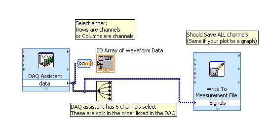
All the inputs of channel must then be read in with a single DAQ Assistant, but all of the data on different channels are not separated. Can save this data in a matrix or otherwise manageable which allow to facilitate the analysis of the data from the separate channel entries?
I tried to view the data in a file of measures, but then when I tried InPort data, I could all the data I wanted.
Hi AggieGirl,
Good afternoon and I hope that your well today.
First of all, you will not be able to have more than one DAQ Assistant by input analog or analog output task because the device has only one of each. So, you must have a DAQ task to HAVE and AO. (This is not the case for DIO static).
There is far from split signals using the express VI - signal splitter.
When you say you saved this file and it does not work, how it did not work? The Express VI - save a file of measures needed to manage multiple waveforms. Can send you your code & explain more about what was not OK on the file?
Thank you
-
At the same time Record several channels in DAQ
I'm currently configured to play two channels in data acquisition using DAQ Assistant. I wonder what would be the best way to go on the sampling of these channels at the same time, or as close as possible. The vi that I currently use is attached.
Thank you
Sawyer
DAQmx manages the calendar under the hood and does it quite well. If you want to change advanced sync settings you can, but of course, you will have to abandon the DAQ ASSistant and write a LabVIEW code.

I assume you are using a multiplexing card right? The only real solution for true simultaneous sampling is to buy a card that has several a/d converters like the S series cards.
For the second poster: you do not have the same problem as the op. It can be implemented in multiple channels. If you want to help, you must provide further information that "it gives an error.

EDIT: I bet you are trying to use separate tasks for each entry, aren't you. If you do, you'll get a resource conflict error. You must use a SINGLE task and set up several channels in this task to collect more than one signal.
-
DAQmx create several channels of
I downloaded the program entry OR bridge-continues and tries to modify it slightly to allow several Wheatstone bridges to connect. Currently, it has the ability to connect to a single channel but don't not to acquire information from several channels simultaneously. All information regarding the shunt calibration, bridge information and waveform graphic output remains the same. Ideally, the program displays the greatest value in the final waveform graph, but it is fine if it shows separate graphs for each of the two entrances. I was playing with it without much luck though if I start from scratch and you use the DAQ assistant, I'm able to get information without penalty. Any help would be appreciated.
In fact you are 99.99% of the way.
You just need to 4 characters
The name filtering on this control is even properly defined to allow multiple selections and just shift click on the second channel
-
Dynamic data of several channels in table, then save in Excel
Hello
I am acquiring data from several channels (4-5) and I'd like to collect samples at low rates (10 Hz for 3 minutes max). For various reasons I use Dynamic Data type, although I know that it is not the best way (some say it is a wrong data type
 ). I also want to save data to a file (the best option would be data excel file).
If I acquire data 10 times per second, it is quite slow to save in excel (this is the slowest option of all types of data). So I would like to fill a table or matrix of acquired data and then write Excel file (I use scripture to measure file). But I don't know how to do - if I convert DDT in DBL, build an array and connect it to change registry, it works but I lose the information in column names and I'm wasting time. If I connect to build the table a DDT and then shift record another, it returns the table 1 d of DDT. I would like to have 2D DDT, which collects all the information loop. Is there a suggestion how to solve?
I'm sure it would be easier solved my problem with the double data type but I also use select signals VI which is the VI I am not able to replace at this time.
Good day
Lefebvre
I don't know if there is a question here, or what. Doing what you say you want to make, acquire the data of 4-5 channels at low rates (10 Hz for 3 minutes) and save the data in an Excel file (I assume you mean really Excel, i.e. a file with the extension .xls or .xlsx) is really a very easy thing to do in LabVIEW, especially if you are not using :
- DAQ Assistant
- Dynamic Data
- Write to the action file.
Indeed, you seem to realize this, but I guess you want to 'do the hard', in any case.
Good luck.
Bob Schor
-
Error in the capture of several channels using pre-trigger
I have problems of acquiring data with pre-trigger samples during the capture of several channels, using hardware NOR-PXI-6071E and Analog Input VIs in Labview (inheritance OR-DAQ).
My goal is to trigger a signal, while capturing another. Unfortunately, I can't use the PFI0 for external triggering, as our cables/material have already been built, so I have to use an analog input as the trigger channel. I understand that to do this I must capture the two strings and the string I want to trigger outside must be the first string in the list.
If I trigger and capture on the same channel (I tried 1-4) then it works very well, regardless of the number of samples before relaxation together. If I capture more than one channel (the channel of the relaxation to a first), with no pre-trigger samples, then trigger and capture both work very well. However, if I do the same thing with pre-trigger > 0 sample I get the following error:
Error-10621 to AI control. Possible reasons:
NOR-DAQ LV: The specified trigger signal cannot be assigned to the resource for the trigger.I don't have to such limitation explained in the user manual, and the forum search, I found a few other people who have had the same problem but they had no solutions. Any ideas?
Hi Jackson,
Unfortunately, this is a hardware limitation when you reference analog trigger via one of the lines to HAVE.
Please see this knowledge base. Particularly the second paragraph says
The error-10621 appears immediately when the VI running if you try to assign scans of relaxation before while scanning multiple channels and using one of the entries as your trigger channel.
Details are explained in the third paragraph:
Because all the entries are multiplexed before being sent for analog triggering circuit, it is possible that the trigger on the trigger channel conditions might miss while the device is multiplexing by another channel. In this case, the trigger will not be detected.
It is explained in the E-Series user manual page 10-3. Specifically the second paragraph of the section entitled "Analog Input Channel".
Eric S.
-
Hello!
I have a problem regarding the acquisition of data from multiple channels. I get a channel data in time, but when I try to do a similar code to get data from another channel, it will not work. This can be done with the DAQ assistant, but I want to avoid this solution, because it slows down the program a little.
The snapshot accessory show how this is done for 1 channel. Can I use a similar program for the acquisition of several channels?
Thanks for your help.
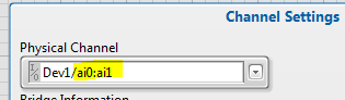
You must only specify several channels in your task - i.e. Dev1\ai0:1 and replace the DAQmx Read N channels. Go to the task in MAX and click the channels button Add. Follow the directions.
-
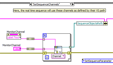
Use several channels in the order of RT
Following this post, and based on a simple sequence of RT that monitors a single channel, now I want to control multiple channels with setting specific time and level. The logic of this was to pass an array of strings that you want to monitor in the .vi create sequence parameter assignment (channel) and use arrays to manage all the time and level settings.
However it seems that the sequence of RT cannot manage this type of object... so, how do I extend this functionality to several channels... Maybe that's the wrong avenue to use rt sequences?
L.
... well, I look at one of the approaches is to create several calls sequence on a given sequence, each with different settings, then start them all in parallel. It seems to work for the moment.
A simple question as opposed to events is used (for now) to detect when each called sequence stops and returns its result.
Laurent
-
FFT on several channels in FPGA
I have a client with a 9076 (Spartan-6 LX45) who wishes to perform the FFT on several channels of a module of 9205.
I never run FFT on several channels and never run out of space on the FPGA before, but I strongly suspect that this could change that. Before I start to code this and play, someone can experience with this scenario - that offer you an optimal architecture / let me know how many channels can I expect to treat?
Hey Jed,.
As someone who has done a very similar application, but with the DC/RMS measurements, I can say with confidence that Yes, this is going to change that... How many channels your client wants to do and what kind of flow? I was able to get up to 64 is going, but it took most all of the fabric, and I had to write my own calculation of DC/RMS multiplex VI. So under a flow of course (I think we had each channel was updated to 1 Hz with 1000 samples per channel). Therefore, when writing a VI that multiplexes across all channel data, you could theoretically get many channels out there, but you sacrifice a flow.
Basically, I modified the existing Express VI to store its State in BRAM between each call and he's travelled to the number of channels * samples I was doing. Not terribly difficult, but your time trying to find a good balance for the given application.
-
Several channels with different frequencies
Hello
I use card NI USB-6221.
The C API using, I need to generate 6 digital output channels, with frequencies of diffrenet and Heavy duty.
To be more precise, the 2 are totally identical, but I need them to be reversed, and the other 4 are similar to another, but should be shifted in time (I.e. There is a delay between each of the channels).
I used the 2 channels of CO that the USB-6221 takes charge for the first two signals, and it works very well (the two signals are synchronized and are reversed).
Now I need an additional 4 channels for the other vague square.
I saw an articale NOR by JohnP web site with the title:
Generate multiple channels of digital output with different frequencies and Heavy Duty
The following example shows how to create and generate a digital with the non-regeneration wave form so that you can change the frequency and the duty cycle on the fly with the M Series DAQ hardware X. The example uses output digital rather than counters to achieve this, so if you need more output than the available counters, it would be a good option (Note: on the materials of the M series an external sample clock must be provided, this may be caused by one of the counters if you want).
that seems to be exactly what I need, but the examples are for LabView which I did not.
Can someone explain how to do this with the C functions?
Best regards
Danny.
Hey Danny,
The important thing to note is that you can clock of arbitrary digital waveform (up to 1 MHz on the 6221). The real data acquisition programming is pretty easy once you have the waveform. My Example LV used LabVIEW Base generating function VIand then converted to a digital waveform to generate the signal from each channel.
The functions of LV helped tremendously with to achieve the waveforms to be updated on the fly (the basic function generator keeps track of phase for you).
If you do not need to be updated on the fly, then the construction of the waveform in C should not be too bad. For example:
P0.0 [1 1 1 1 1 1 1 1 1 1 0 0 0 0 0 0 0 0 0 0] * 1
P0.1 [0 0 0 0 0 0 1 1 1 1 1 1 1 1 1 1 0 0 0 0] * 2
P0.2 [0 0 0 0 0 0 0 0 0 0 1 1 1 1 1 1 1 1 1 1] * 4
P0.3 [1 1 1 1 1 0 0 0 0 0 0 0 0 0 0 1 1 1 1 1] * 8
[9 9 9 9 9 3 3 3 3 3 6 6 6 6 6 12 12 12 12 12]
The table above U8 would give you 4 output waveform of 50% duty cycle at Fs/20, shifted 90 degrees to eachother. The lines would be p0.0 by p0.3 (the bit rate of the U8 corresponds to what line goes high).
Best regards
-
Reading and recording of several channels simultaneously
I use a NI PCIe-6363 map to acquire data from various sensors in an experimental engine. I need to be able to show views and record data on all channels simultaneously. I'm relatively new to Labview, so I think I'm doing things inefficiently. I am also having a problem with the display of multiple signals. I have attached the vi. I look forward to the advice.
DAQmx is able to take multiple samples at the same time, so you need only a wire covering your While loop. See this example VI that comes with LabVIEW. You can find others with the help > menu examples and digging from there:
C:\Program Files (x 86) \National Instruments\LabVIEW 2012\examples\DAQmx\Analog Input\Voltage - Input.vi continues
Initialization DAQmx VI would need another kind of entry rather than "PXI1Slot2/ai0. I forgot the exact syntax, but it would be something like "PXI1Slot2/ai0-15". In addition, the read DAQMx VI is polymorphic, so that it can read all these channels in sub form of table. Then, you have to build the table of these PXI objects to initialize DAQmx VI with the function 'Building the matrix' of LabVIEW and indexing table in 16 items with function "Array Index. You only have a single function Index Array, expand right down it and it automatically will give you items between 0 and 15 (or however far you develop) without having to wire in all indexes.
-
I have a DAQ Assistant configured to read 2 channels at the same time. When I have a graphical indicator of wire to the output, I see 2 signals mixed together. How I divided them into separate signals?
When I wire any type of indicator, it is show that a release of a single channel.
I want 2 indicators showing 2 different signals as expected from 2 channels configured. How to do this?
I tried to use split signal but it end by showing that 1 out of 1 signal two indicators.
Thanks in advance.
Yes you are right. I tried, but I don't have the result.
I just find the path. When we launch the split signal, we should expand it (split signal icon) by top, not the bottom. It took me a while to understand this.
Thank you
-
How to read several channels simultaneously with a minimum
Hi all
Please see the attached file. In fact, this is a simplified example of my real application, I didn't understand the second half to reduce the complexity.
As demonstrated, I have two entries of analago I need to read (position and acceleration) with a SPECIFIC requirement which is:
At the same time, I make some decisions based on data more recently acquired in the "timed loop. The decision part is not included in this vi. for simplicity. But the fact is that I just need the most recent data (as well as online) make a kind of decisions.
Everything seems fine and it seems that I collect data in a way desired interval of 1msec. BUT I just discovered that the data I read (in the timed loop) are the most recent one compare is not to the real sensors. In other words, there is a delay in the acquisition process. The value in the timed loop is like 100 msec delayed the release of real sensor, which is generated by the sensor and acquired by DAQ card.
This problem makes my decision making part of constantly decide according to the before value of 100 msec. Unfortunately, it's terrible to my request, i.e. it is an intolerable delay to the process.
Are my settings of data acquisition as samples per channel, the number of samples per channel or right of sampling rate? I appreciate if someone can help me with this application. I just need to collect data at 1 kHz, as close as possible in real-time (online) or with a minimum delay, not 100 msec.
Thank you.
-
Several channels of FP-I-110 - degradation of Signal
-
Several channels of voltage measurement
Hello
I want to measure two different voltages of the two channels to a single device.
I looked at several examples, which I understand. However, I still can't figure out why my code doesn't work.
Here is a simplified version.
Thanks for the help.
I use a box USB-6211.
Thank you to try, I just connected a second voltage signal - now everything works fine!
It was probably a problem of grounding!
See you soon!
Maybe you are looking for
-
USB - C adapter AV digital Apple Multiport is directional
I just bought a new 12 '' MacBook and also USB - C Digital AV Multipart adapter Apple. The first time I plugged it to the adapter, I received a message on the screen telling me there was an update for the card and I wanted to install it. I ran the
-
Need for DVI, HDMI on Satellite A300-15 b output
My toshiba laptop Satellite A300-15 b has only a VGA and S-video out;It has an Ati Radeon HD 3650 512 MB graphics card that supports hdmi and dvi, FullHD; I know that dvi and hdmi are of better quality than vga, so how can I connect my laptop to the
-
Office home and Student 2007 will be not updated
I just bought this package of office 2007, it installed on my laptop Vista well, the only problem is that it will not be updated with the update program. I also tried to install some updates manually, no use. I'm now 14 updates (Important). I tried t
-
OfficeJet Pro 8610: Booklet in .pdf format
Booklet used in .pdf for a project, now cannot return to normal printing (all still print as a booklet)
-
Why is audio from my PC (which is coming through my headphones) also be picked up by my microphone?
For some reason, whenever I am watching a YouTube video, play a video game or edit a video, my friends that I talk on Skype can hear what I mean. According to them, it sounds of frying. Sometimes they hear him stronger than me, and sometimes they don