flashing boolean outputs
I'm starting to learn Labview and I created a demonstation VI just to familiarize themselves with the feature.
I just put one on and out (blink) output based on a cycle, I put, through the user interface.
I know that I do not understand loops very well because when I try a loop it just stays there and the rest of my program is not moving forward.
I will attach where I landed, maybe I need a sequence or other funciton of control, I'm not sure.
You have to really use the outer while loop to the shift register, otherwise the inner loop delays the outer loop. (You can also use a node initialized worldwide comments)
You also have too much code duplication. You can use tables instead, simplify code. Do you think all of the lights to blink or just #2? Here's a solution that flashes everything and uses tables. Modify if needed. See if it makes sense.

Tags: NI Software
Similar Questions
-
Adobe Flash CS6, output limited
Hi guys,.
I'm manipulating a chunk of data in flash and I need to trace a certain serious written in the output panel, but when I look at is always truncated:
[... truncated text]
No idea how to remove the restrictions of output panel charaketer?
Thank you
-
reset the boolean output when the elapsed time is reset
Hello
I used the function time successfully, but after a reset, the Boolean result is still high.
Can someone tell me the best way to reset this please?
Thank you very much
OK - sorting, thank you
-
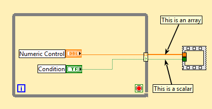
Bug of output conditional Boolean autoindexing
It's a little subtle, so I apologize in advance for the possible confusion.
Start with a While loop and conditionally autoindex a scalar:
Example 1
As noted, the Boolean result is a scalar.
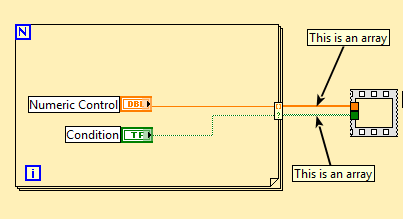
Now try the same thing with a loop (DO NOT REPLACE THE WHILE LOOP above by a For CREATING a BRAND NEW LOOP FOR loop):
Example 2
OK, so now the Boolean result is a table. Cool, that's what I wanted with the While loop above, but could not achieve.
Now you can play with replacements:
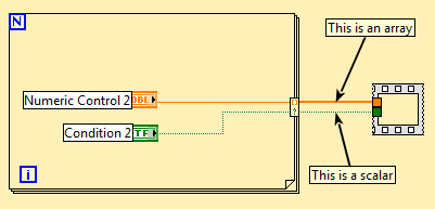
In example 1 above, replace the While loop with a loop For. Here's what you get:
If you CAN produce a Boolean scalar value in a loop For, but you have to go through a While loop to get it.
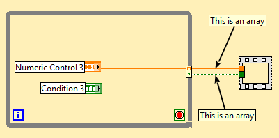
Now replace the loop in example 2 by a while loop:
All right, here's my table Boolean output. But I had to go through a While loop to do.
I'd say it's a bug, and the Boolean result of conditional indexation should be a table (not sure if there would be any how to have it be a scalar; last exit value?).
Tested by LavBIEW 2013 SP1 64 bit
Sam is correct: the conditional Terminal is not out of the loop for. When you "dragged through" the sequence you actually create an output of indexation of array of Booleans (unconditionally). Click on "cleaning chart" and you will see this. (I guess it might be a bug that LabView allows two nodes to overlay on the same place in the loop).
Moreover, you can always get a scalar to a loop for. right click on the tunnel, set it to "last".
-
Values in the array of Booleans to dictate the output to be Boolean False or Boolean True
I have a pretty simple question that I have a problem to solve.
I'm looking to enter a Boolean array for a sub - vi that will take this table and dictate a single boolean output Boolean false or Boolean True.
For example, the table will be table boolean 1 d, with a depth of 2 index values.
-If the two index values are wrong then the sub - vi will kick for a False value.
-If the two index values are true then the sub - vi will kick on a True value.
-If an index value is True then the sub - vi will kick a True value.
Any ideas?
Thank you.
jonathanupr wrote:
-If the two index values are wrong then the sub - vi will kick for a False value.
-If the two index values are true then the sub - vi will kick on a True value.
-If an index value is True then the sub - vi will kick a True value.
It sounds like an RC for me
jonathanupr wrote:
For example, the table will be table boolean 1 d, with a depth of 2 index values.
I don't know what you mean by that. How you choose to use indexes?
EDIT: Perhaps you need some Elements of array or
-
Control the Boolean commands and generate a corresponding digital output
Hi all
I'm working on a project of activation of the electrode, here, I thought that how could I order an electrode in a time and generate a digital output of it accordingly. I want to replace it with each electrode with a LED on the front panel and generate a numerical value to each LED on the block diagram.
If it can be divided into two parts
1 control the Boolean outputs
Here, my goal is that if I have 5 leds that are used as a Boolean control, must be ordered so that only one of them lights up at the same time and the rest goes off.
I mean for example if #3 was turned on and that the user pressed the #3 #2 should be turned off and only #2 lights.
2. generate the corresponding numerical value
Depending on the position of the LEDs I want to generate a corresponding numerical value, as previously released 3 coming and exit 2 then comes when the second LED illuminates.I ask all participants to this group to help me with this.
Concerning
Why don't you use the radio button control? You can replace the boxes if you want the buttons.
-
I need help understanding the passage Boolean ptbypt and I need help for her to run only once, from bottom to top. (or true false) I'm trying to catch a digital input when it goes from low to high. I want to catch the first low to high, then go in my code. (registration data). Right now I measure data on secondary 2, I want to change that to capture data as soon as my DI goes from low to high, only once.
Use a feedback node that will be followed if the Boolean crossing happened before or not. (You can use the Boolean output from a level crossing as the input to another to detect this.)
Remember Feedback nodes and Shift Registers to keep track of what's happened in the past. You just need to Boolean logic with Boolean such as functions and and or to do the rest.
-
Best way to make a simple Boolean test?
Hi all
Try to do a simple Boolean test, but it is more difficult than I expected. I hope I'm missing something simple.
I have a module of Labview code that provides a Boolean output. I want to evaluate this value and provide the report pass/fail results. Sounds simple, but here is what I'm running into:
-Step OR built-in type "pass/fail Test" will evaluate the Boolean value directly with Pass = True and False = Fail. It would be nice, unless I have situations where I need to Pass equal false. I read a few posts talking about reversing or annulling the Boolean result, but they are all passing the result to a variable or a parameter and then evaluation outside of the test step. This adds several layers, I don't think that I would need.
-J' read a post that suggested that convert the Boolean value of a digital inside the code module. It is indeed logical, but is not practical in my situation because of the scale and the implementation of my modules of code. I use the definitions of custom type for controls and indicators a Labview project and would have to create a new control/light for everyone if I wanted to change the data type.
-Logical extension was to see if the 'numerical limit Test' would recognize a Boolean value. It turns out that it is not.
-After that, I looked in the creation of a custom step type. It would be probably the most useful, but this is beyond my current capabilities to do so. I had as far as making a copy of the stage built in type and put in the MyTypes 'custom' directory, but I made very little progress in editing to make it work. In addition, I read a few messages that recommend to avoid the custom step types.
Hoping someone can point me in the right direction. Please notify.
Thank you
GSinMN
GSinMN,
I would enter "Step.Result.PassFail" for the Boolean output on your VI parameter (kinda like a normal part of pass/fail Test), and on the Data Source tab, you can add an exclamation at the front, for example:! Step.Result.PassFail. This will reduce to zero the value of production and use the result of this for the comparison.
If you want to save the actual production of the VI to the report (for example), you can check the "Log" option for the setting in the module settings.
-
Boolean switch rendering time.
Hi all
I have LabView of issue of a signal of my USB-6501. The output signal triggers a relay and turns a solenoid switch.
Currently, I have a Boolean value, implemented as a button where to click to activate the signal, then click on to turn it off. In turn the valve opens and then closes.
I am extremely inexperienced with Labview and was able to find enough to implement, but it is difficult for me to convert what others similar, but different set ups, have made the forum search.
What I have a problem with now change this code in order to have clicking on the Boolean output affects the signal for a while (let's 500ms) and then turned off automatically (without having to set). Basically a pulse. I feel that this would imply the loop any set with a timer, but I'm not sure how to start setting this up.
I have attached my LabView code for you to see. I would appreciate help. Thanks in advance.
I recommend using a Structure of the event. On the change of Boolean value, you set or reset the output. Using a registry to offset, you can also set the timeout for the structure of the event. Then in the timeout, use a Value property (signs) of the Boolean to force a change in value to the Boolean false. This will result in event of change of Boolean trigger and consequently cause your output turns off.
-
Capture the output of command Unix in WLST
I'm trying to write a Python/WLST script that connects to a particular area based on the machine on which the script is run. My thought was to issue the command of Unix 'hostname' get the name of the machine operating systems, test against it and connect to the output of the base. My first thought was to do something like
Import os
HR = os.system ('hostname')
If HR == "name":
ConnectToAS()
It does not of coarse because the os.system () command returns the Boolean output from the statement code and not the output. I then tried to watch using the mod 'subprocess' but who returns the following:
Problem call WLST - Traceback (innermost last):
File "/ home/beaadmin/bin/scripts/wlst/wip/checkMachine.py", line 1, in?
ImportError: no module named subprocess
Anyone know of another way to run a Python/WLST script which get the name of the machine on which it will run and make the name available for the rest of the calling script?
Any help would be greatly appreciated.I came across your post looking to solve this same problem. I found a solution myself. Since jython, you are allowed to use a java class in your python code. So to get your local host name, use:
HR = java.net.InetAddress.getLocalHost () .getHostName ();
-
Format options for AE CS3 - Adobe Flash Video - causes the crash
As the title States. I see so many people say Adobe Flash Video is the way to go for export options still AE always crashes on me when I choose it is-Options of Format (output module in the render queue).
I use Flash all the time and it works fine but since I can't access format options FLV of AE. Whenever I press on it AE crashes everything.
It's one of the things Adobe just never fixed in CS3? I don't bother to read reviews saying to use anything else to make it. This is not what I am asking so save. I created a simple object in AE and I just want to see what it looks like with FLV export. AVI seems good but looks like everyone said it would be better as FLV. Given that I can't access the options of format to FLV is the worst option and unclear, which leads me to believe he was one of those things Adobe just abonded in CS3.
I searched and found nothing. I will continue my research, but the choice of Adobe for the format of forum could not be slower. If Adobe can answer this question, perhaps I can shed some light on the economies of its members an agony and teach them some PHP. It's rediculously slow and my worst forum puts it to shame.
The implementation of FLV in CS3 left a lot to be desired and video Flash - both FLV and much F4V the best and the most recent- are much better in CS4 and later versions. (Don't forget that Adobe acquired Macromedia just before CS3 came out, so it was not a lot of time to get solid integration.)
If you can, I recommend using something later than After Effects CS3 for Flash video output.
-
ProBook 450: 450 ProBook G0 does not start
When th epower button, the CPU fan starts and runs too.
The CAPS LOCK button is flashing, the led for the power adapter, and that's all.
I can't enter the BIOS by pressing F10, and nothing is displayed on the screen.
There is no connected peripheral devices.
I removed the battery adapter and network and the press and held the power button for more than 15 seconds as described in another article - same symptoms, IE, CAPS lock key blinks, flashes for the power adapter, and that's all.
I deleted and reinstalled the memory module and tried starting the machine - the same symptoms, IE, flashing CAPS lock button, the light output for flashes of power adapter, and that's all.
I removed the hard drive and and tried starting the machine - the same symptoms, IE, flashing CAPS lock button, the light output for flashes of power adapter, and that's all.
I reassembled the nd machine and tried starting up again - same symptoms, IE, CAPS LOCK button flashes, light output for flashes of power adapter, and that's all.
I tried NOT to use the power adapter, just switch on the machine with the battery cover - soul symptoms, IE, flashing CAPS lock button, the light output for flashes of power adapter, and that's all.
Anyone have an idea how I can at least get into the BIOS or run any diagnostic tests? If I could get here, it would be a start.
It's a dead motherboard. I'm sorry.
-
Creating a string of bits to send through questions series VISA, complete noob here...
Hi all
I'm trying now, to browse the values I have on my collection of GUI and with these, construct a message to send through VISA.
I have the usb-> rs232 cable and NO, and I have attached a connector, with the pins 2 and 3 tied together so that I can loopback and see the messages I send.
I'm supposed to (from the instructions that I read on a design doc) will send a message of length of 24 bits.
And please bear with me, I've never worked on this low a level before, nor with the serial interfaces, so I can be completely off on how I'm doing... and this is my
first really relay with LabView for this project.
I have some time execution of every 20ms in a loop.
I have a structure of the event looking for user actions on my front.
I also breast that everything in a loop, a flat sequence structure... my assumption was, every 20ms, the flat sequence structure would run, except where it is interrupted by an event... that could trigger and then continue with the flat structure...
I have seen that the entry VISA (and read) take a string.
So, I started the flat structure with build my string of bits/bytes outgoing... first section is coded hard and then, through the two sequences, loop it and based on the values of the controls within each cluster, I concatenate to my outgoing string... in which case, I send by the visa by the closure, and post it on the message indicator.
It seems that I can send on only 8 bits at a time through VISA... so, I try to understand (and I wonder people with the req on this part) why they said to send such a long chain... or am I supposed to send each message of 8 bits, one at a time?
If one bit 8 message at the same time, I wonder how I have let him know when I am finished? I have heard and read things about start and stop bits, but I don't know where to put them.
In addition, is the string that I'm supposed to put them together to send something waiting for data series bits/bytes? I saw a reference to a string of bytes while the research, but I Coulnd't ' t find a piece of string byte on the pallets.
And when I run the present (a simpler example of my real application, simply to show here the parts I am trying to figure)... the message echoing again to me is:
111000010000\n
When if I have all the tubes with a value in them... I want to get something new like:
1110000111111110111111110\n
I'm also noting that messages do not seem to be transmitting every 20ms... seems only to get a message back when when I trigger an event, as the option switch on the LED.
In any case, I'm confused, I think that, on certain basic principles and hope someone can maybe send me some links or give me some advice on where I'm wrong so seriously...
Is my construction of the right to follow path string message?
Is something wrong with the flow of the program... the events + flat sequence structure?
I received this property by searching for forums and other papers OR, but I'm stuck sort of and confused I think on some concepts with read/writes...and possible VISA my flow control.
Any suggestions and/or links GREATLY appreciated.
Thank you
Cayenne
PS. Some asked to record for older versions, so I enclose a copy saved to more 2011 v10
Cayenne,
Your sequence structure is not necessary. You have a dependency on the data, as well as the structure of sequence is not really do anything for you. Seems to me that what you want to do is to build the table of your clusters that you already own and send the table directly in a > 0? function. It will accept berries and an array of Boolean output. You can then use the Boolean array to the Number function to create a U8. Do this for each of your clusters and integrate the results in a table of U8 and fixed data. Then use the array of bytes to the string function to get a string to pass in the VISA to write it. Without loops or the necessary structures. Any additional manipulation you need, I recommend to the byte level.
-
Complete the step sequence of pass/fail
Hi all, I have a step in my main sequence that runs an interactive dialog to the operator. It checks whether or not he receives the notification of the slave device. If for any reason, the operator wants to "put an END to (ABORT" dialog box, I have a "CANCEL" button on the Panel before you let them.
I want that this sequence step to behave as follows:
1. If COMMUNICATION RECEIVED = and the ABORT BUTTON = DO NOT SHOOT, then the status of the step should = success
2. if COMMUNICATION = NOT RECEIVED and ABORT BUTTON = DO NOT SHOOT, then the status of the step should = failure
3. If the ABORT BUTTON = PUSHED while in the IMMA step running, then the step status should = Terminated
Currently, I have the stage set up in a time of pass/fail using a Boolean output value of the VI. My problems is that I have a problem with point 3 above. I'm just putting it in the Expression of Post for the step in the following dot handle 3:
Locals.VIAborted is True? () RunState.Engine.TerminateAll & Step.Result.Status == "completed":
Sometimes, I see not end when the Abort button = Pushed.
I'm this treatment properly, or is there a better way to do it?
Thank you very much!
That's all... Thank you mkossman!
-
Any problem of loop sampling frequency
Hello
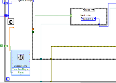
I am a student who did a thesis on the electric vehicle tracking system in labview. I collection of usb-6009 analog measurement data, transfer it in the daq assistant and state machine inside a while loop to do the follow-up process.
So, I have a State that determines the sampling frequency of the loop cycle, and I was able to modify this rate in the values of 0.1, 1 to 5 Hz, I realized that it with out of time VI Express, which is in a loop, but outside the case of structure for States. I'm going to rate last in time "Target Time" of entry and the Boolean output "Elapsed time" goes to the business structure, passing to the next state when the time runs out. In the next State, it resets the elapsed time and the cycle starts from the beginning.
Thus, everything works fine until I see in my log file (txt file where I save the measured values) it's only 3 or maximum 5 Hz frequency 4 samples per second.
I have a good enough computer with processor i7 and 8 GB of ram.
What could be the problem?
In the picture below it can be seen how I realized that with timer.
Thank you in advance.
Matej
As I mentioned in my previous note, your problem is that you start a new target for the time time vi ONCE your analog playback is completed. This ADDS essentially no matter what time is taken by Analog playback on top the time you ask vi of time spent waiting.
I modified your vi and I think that should take care of your problem of synchronization.
However, I suggest using "Wait until the next ms Multiple" because unlike the vi express you are using, one I mentioned allows other processes are doing their job in the meantime.
Hope that helps...
-DP
Maybe you are looking for
-
my itunes store is not synchronized with my cursor
Since a recent update I can't select an application from the store because the next door opens. The Guide to move in the page line is also about 2 inches out.
-
How to connect by Satellite M105-S3084 on TV?
I have a Satellite M105-S3084 equipped of XP SP-2. How can I connect to a TV so that the image appears on the TV? I looked at the manual and it doesn't have a description of the ports on the back and sides of the laptop, or it identifies not what kin
-
I use a site about 2 or 3 times a week. After registration on the site, it should redirect me to another page but always request my permission to allow.In tools, Options where it allows me to give automatic approval to be redirected. Otherwise, I'm s
-
What is the best vpn for OS 10
What is the best VPN for my MacBook Pro running Yosemite
-
WPF chart - select a horizontal range
Hello I use the chart WPF of MS2015, I want to allow the selection of a range of horizontal (without zoom) so that the user can see the selected range. 1. How do I allow to select the horizontal range in the chart? 2. the data graphic is ChartCollect