Foglight DR Flip Flop
We must make a DR to flip flop on a host where foglight has been installed. The host is currently monitoring on Foglight5. How can we move the FGLAM from host to host DR.
Please help me by providing all the necessary steps to migrate with success the foglight to host DR.
You must keep this SOIL in mind when developing a DR solution
https://support.quest.com/SolutionDetail.aspx?ID=SOL84961
Tags: Dell Tech
Similar Questions
-
Hi, I am a new mechanical engineer for labview and should help create a vi that can do the following flip flop function as shown in the attached search.
Thanks to uploader if possible vi...
Thank you
Avinash
Laboratory of IC engines
IIT Madras
Your context is not clear at all.
example of iFor, f is a response like a mouse user, click then your problem is easily solved by changing the mechanical action of the Boolean button. This link gives more information on this. http://zone.NI.com/reference/en-XX/help/371653B-01/lvhowto/changemechactofboolswitch/
What is an external pulse signal traced on a waveform? If so, then that is a table format and you can use the table features to compare and activate a Boolean indicator
Please explain more about your problem.
-
Simple simulation Flip Flop. Flashing LED problem
Hello!
I have a problem on the simulation of a circuit simple flip flop. The output is connected to a LED for the indication of the output. However, the lights just keep blinking which gives me the impression that the output is not stable (which from my analysis, the production should be stable). I'll post a picture and the file multisim for you to see the circuit. Thank you!

I don't have a Multisim, so I can't comment on the issues of simulation directly.
I was about to raise the issue of V/15 V 5. As well, a typical LED work to 1.6 to 3 V according to color (and thus the composition of semiconductor). Try LEDs by car directly from the output of a 4011 will cause problems (in a physical circuit). The current Ioh source for the 4011 is 8.8 my typical and 3.4 my minimum at 15 V, assuming the Voh = 13.5 V. A typical LED voltage current could rise to 32 my (~0.5 dissipation W!) until the device goes up in smoke! But with tension that low, the logic of feedback will not work because the output voltages will always be below the other door entries.
The simulation does not reflect accurately the limits of current and voltage outputs.
When I put in place a fast simulation of logic in LabVIEW, I find that there are some unstable States. This logic includes a delay effect, but assume ideal logic levels.
Lynn
-
Hello
I am trying to simulate a binary counter with the help of JK - FF 2 but is does not work. I tried another way, as the test 2 JK - FF with individual clock (clock 1 and clock 2) and LED (LED 1 and LED 2). When the clock 1 is enabled, clock 2 is TURNED off, LED 1 and LED 2 is on. I spent a week to solve the problem, but it does not work. Please, help me. Thank you.
Go to the properties of VI, run for your sub - VI flip-flop and make it reentrant. In this way each instance has its own State of memory. As it is now also non-reentrant, each call to the Subvi only goes in a single memory state, and so the other flip-flop is to remember how feedback records have been established in other cases where it was called.
-
Flip-flop not transferred to Ultiboard
Unusual problem. One of the components in a Multisim schematic, one 74LS74 9, will not be transferred to Ultiboard. He went completely from the netlist Ultiboard, but still appears in the netlist Multisim. Too often "Virtual component not transferred" message, but here the of no indication what element it is. The 74LS74 seems to be a real component in all directions. How can I fix? Thank you very much. JK
One of the other good guys here at NOR fact the following suggestion that took place to work great:
Double click on the 74F74N select the "Variant" tab, under the "Status"
column, change the setting from Excluded to Include, I am not sure what
caused this problem,  I've modified the component and the file is attached.
-
lock to pass a Boolean conversion or enabling / disabling flip flop in labview
I am a newbie of labview, and I was scratching my head on a particular problem.
I want to use a joystick (11button, 3-axis) to operate the 2 steps in microscope of PI in tandem. I think the best solution to this problem:
the buttons of the gamepad provide engaged Boolean: they are true only while the button is kept pressed. Once the button is released, the Boolean value becomes false.
I want to take this rocker and produce a Boolean value true the first time the button is pressed and change this boolean a false when the button is pressed subsequently.
My current idea is to try to build something with a case or reporting structure, or even something like a Boolean value for whole conversion then division modulo-2.
Can someone give me some advice here?
Thank you!
zipmanx wrote:
From a programming point of view, which is preferable to use? a handler as too has suggested, or something like an event or saying?
Here's another one: you can make a change to the level of the ILO in labview?
Since you are reading material, you probably need to polling, if an event is released.
Yes, you make changes to the level of the ILO in LabVIEW. Look in the "digital... data manipulation" palette.
Here is an opportunity to resolve your problem (LabVIEW 8.5). Well, there are other ways to do it, but dfefinitely you don't need blue wires for the logic.
.
-
The Photos app is causing me much confusion! I have an iPhone, iPad 9.7 Pro, iMac and a MIni iPad and I can't get the pictures that I take for example on my iPhone to my iPad and iPad Mini. All these flip-flops slider in settings Photos confuses me, I tried more to what they are supposed to do, but nothing helped. I 1 222 photos on my iPad, 1209 photos on the iPad Mini and don't know how on the iPhone but it is more than the iPad.
What is really confuse me are the two sliders that say 'Optimizes storage iPhone' & 'download and keep the originals '.
The two option say that iCloud photo library will be removed from iCloud within 3 days.
Advice or instructions about what to do with this application, so that any device I use to take a picture, it syncs to other devices including my iMac.
Thank you.
Take a look at these two articles to iCloud photo library. They should answer your questions:
iCloud Photo library FAQ - Apple Support
iCloud Photo Library help - Apple Support
See you soon,.
GB
-
Re: Satellite S2540-101 - the display hinges are dead
Anyone know where I can get a new screen for my Toshiba Satellite S2540-101 hinges. Flip flops on screen at 180 degrees!
I tried eBay and nobody seems to have any!
See you soon
Dave
Hi Dave
I can imagine that it can be difficult to find these pieces for this older model laptop. eBay is the right place to search for such parts. You can try to contact the service provider allowed in your country, but I'm pretty skeptical, they will be able to order these parts.
But I think they can help you and give you the exact order number. Using this issue maybe you will be lucky and find this Googling pieces around.
-
Cannot restore Apple TV 4th Gen in iTunes
So, just got a new 4th Gen Apple TV and not been impressed so far.
I have unboxed product, hooked up to my TV to see that it is in Chinese. The remote is also inadmissible. I can press the Menu and Home of the SIRI remote simultaneously, and which will restart the Apple TV, but Menu and button fail to re-pair the remote control +.
After reading the forums, I thought that maybe the answer has been to try to restore through iTunes. So I went to search the town for a USB - C cable (hard to find, by the way). Finally found the adapter and then had to buy a $27 usb transfer cable plug of the adapter on my Mac. With high hopes, I followed the outline on the Apple Support page for the restoration of your Apple TV from iTunes, but more problems... Unfortunately, iTunes can't find the Apple TV. It never appears in the upper left screen. I have unplugged, replugged, flip flop cables... Nothing.
I checked and am running the latest version of iTunes on El Capitan.
Does anyone have a way for me to hack this thing and reset it? I read that you can try to control it with an old Apple TV remote to restore so that addicted to television, but I do not have an old Apple TV remote (I put in a call to a friend who has a well and hoping that I can borrow him soon). I called Apple Support and they shipped me a new remote to try, but hope I can find a way to fix before he gets here.
It has been one thing after another with this device. Very frustrating. Hope that this is not a new trend for releases of apple products.
Suggestions are welcome!
The only other option would be to take it to Apple so that they restore it
-
Hello
I'm trying to synchronize data between two different instruments using LabView.
A single instrument will work regardless (it can be integrated with LabVIew for various reasons) and the synchronization signal of this instrument, which I want to use (5.76 square pulse, 25 ns wide V, occurs aperiodically) is "extracted" (I made a breakout box and have the synchronization signal on a coaxial cable that I can plug into anything).
I want to take this synchronization signal and use it to trigger an event in LabView (the second instrument is controlled with LabView).
I had hoped that a USB 6501 would be able to go around, but I realize now that he can't see a signal that is so short (I think).
So, what should I do? How can I make LabView 'see' a such narrow pulse and use it to trigger an event?
In summary:
- Have digital signals from a piece of hardware on a coaxial cable - 5.76 V rectangular pulse, wide 25ns, occurs randomly nut not more often than every ms
- Want to get the digital signal into my PC and LabView where I use this signal to trigger an event (in this case, to start an event of data acquisition on a different piece of hardware that is controlled with LabView)
- I'm using LabView 2013 64 bit, Windows 7 x 64
- I was hoping to use NI USB 6501, but I'm not sure it's possible, given that the impulse is so narrow
- Picture of the sync signal as seen on a scope is attached (note there is a tiny little ring that will not present when I fix the cable)
Thank you
Sabrina
Hello
You could use a flip flop to intercept the signal. Do not attach the pulse but the front. You can read the regular output of the scale with any hardware DAQ (digital or analog) and use the same DAQ hardware to reset the flip-flop.
Kees
-
Generate analog output waveform finish on request
Hello.
I have a VI that reads in two data channels (400 samples at 400 Hz), calculates the characteristics and classifies data based on a model. If the class is a certain State, a Boolean value called "Détection" is set to True. A second Boolean value called "Stimulation" is also set to true and flip flops and turn off every second up to what the "detection" is more true. Now that I am reading and classify a second data, Boolean values may only be updated once per second. I am wanting to generate output "Stimulation" Boolean is true analog. I had been accomplish this by generating a sinusoidal signal all the time and write to a buffer in a separate loop (500 samples per writing @ 10 kHz) and multiplying by zeros if "Stimulation" was false. I have a code that more or less does what I want, but there is a delay of ~ 200ms between 'Stimulus' is set to True and AO generation, and I feel like it could be simplified. I was wondering if it would be better to generate a waveform finished and trigger to write with the Boolean value of 'Stimulus' (i.e. write 1 second of a sine wave to the changing state rather than write 20 sections of a sine wave in a second, while the Boolean value is True).
Y at - it a good way to do this with daqmx functions? (Generate a waveform of defined duration when a control changes)
-
In Matlab FIR filter for bandpass sampling and 250 to 700kHz frequency 250MSPS
Hi all
I want to design filter implemented on FPGA with a settings mentioned in the question but when I start to design it on matlab fdatool, it gives very high order filter result, when I decrease or set myself up to 10 order its impulse response is not good, as I hear it.I use high-speed ADC with the 250MSPS.
Any idea will be very appreciable.
Kind regards
UmairUmair salvation,
You can theoretically designated any filter you want in an FPGA. If you can implement the filter on a FPGA target is another story.
There is usually some limitations on an FPGA, that one must take into account:
-Number of flip flops, READ...
-Maximum fare of lines
-Number of available multipliers
It is almost impossible to tell you, if you can implement your filter on a given target FPGA. The only way to get the right answer is to try it. A filter with the command = 50 could be really large and maybee does not fit on the FPGA or does not respect the loop rate you need.
I do not use the FDATOOL, if I can't give you an answer to your second question.
Stephan
-
ERROR: TclTasksC:process_077: in the FPGA Compilation
Hi all
I use for my application in which I am facing following error when compiling my fpga code compact rio 9072:
Compilation failed due to an error of Xilinx.
Details:
ERROR: TclTasksC rocess_077: did not finish. Please, look in the newspaper and report files.false
When running
"process run"card.
(file "C:\NIFPGA\jobs\XI64xG6_My449tj\map.tcl" line 6)ERROR
ack:2310 - type compositions "SLICEL" too found to adapt to this device.
ERRORack:18 - the design is too large for the device and package.
Please see the Design summary section to see the cost estimates for
your design exceeds the resources available in the device.
NOTE: A file NCD will be always generated to allow you to examine the mapped
Design. This file is intended for assessment use only and will not be processed
successfully through NOMINAL.
This NCD mapped file can be used to assess how the logic of the design has been
mapped in FPGA logic resources. It can also be used to analyze
preliminary to the level logic (route pre) calendar with one of the static electricity of Xilinx
analysis of synchronization (PRHT or Timing Analyzer) tools.
Summary of the design:
Error number: 2
Number of warnings: 69
Use of logic:
Number of slice Flip Flops: 7 886 on 15 360 51%
Number of 4-input lut: 16 104 on 15 360 104% (OVERMAPPED)
Distribution of logic:
Number of slots occupied: 8 744 7 680 113% (OVERMAPPED)
Number of slices only related logical container: 8 744 100% 8 744
Number of slices that contains no logical relationship: 0 to 8 744 0%
* See NOTES below for an explanation of the effects of unrelated logic.
Total number of 4 input lut: 17 400 on 15 360 113% (OVERMAPPED)
Number used as logic: 15 998
Number used as a middle way: 1 296
Number used as Rams 16 x 1: 82
Used number recorded the shift: 24
The logical Distribution report slice is not significant if the design is
too mapped to a resource not slices or if Placement fails.
Number of IOBs servile: 183 on 333 54%
BIO flip flops: 74
Number of RAMB16s: 1 24 4%
Number of MULT18X18s: 2 on 24 8%
Number of BUFGMUXs: 4 to 8 50%
Number of DCMs: 1 on 4 25%
Fanout of the Non-horloge nets on average: 3.38
Peak Memory use: 361 MB
Total in time REAL in the completion of the card: 1 dry 12 mins
Time CPU until the end of the total map: 1 dry 12 mins
NOTES:
Related logic is defined as logical that share connectivity - for example two
Lut are "related" if they share common inputs. During Assembly of the slices.
Card gives priority to combine the logic that is related. Generates so
best performance of synchronization.
Without logical report does share no connectivity. Card will start only packing
logic not related in a slice once that 99% of the slices are held through
logical packaging partners.
Note that once the logical distribution reaches the level of 99% by related
logical packaging, this does not mean the device is completely used.
No logical report package will begin, continuing until all usable LUTs
and FFs are busy. According to your timing budget, an increase in the concentrations of
logical packaging unrelated can adversely affect the performance of timing set
your design.
Mapping performed.
See the report of map file "toplevel_gen_map.mrp" for more details.
Problem encountered during the packaging phase.
Failure of the process 'Map '.Start time: 18:29:23
End time: 18:44:42
Total time: 00:15:19Can someone tell me why this error came?
Thank you best regards &,.
Vipin Ahuja
Vipin Hello,
It seems that your code requires more resources that are available on the FPGA. Optimizing your code can help to solve your problem:
You may have noticed some "Overmapping", mentioned in the newspaper:
Number of 4-input lut: 16 104 on 15 360 104% (OVERMAPPED)
Distribution of logic:
Number of slots occupied: 8 744 7 680 113% (OVERMAPPED)Take a look at this article:
http://digital.NI.com/public.nsf/allkb/060BA89FE3A0119E48256E850048FFFE?OpenDocument
And this:
http://digital.NI.com/public.nsf/WebSearch/311C18E2D635FA338625714700664816?OpenDocument
Kind regards
Navjodh
National Instruments
-
VI quadrature encoder does not work after programming of FPGA
I'm rather new on the MyRIO, and I work on the motor of the MyRIO and read control in a quadrature encoder at the same time. Programmed individually, the two pieces of work at Marvel, but once I have combine them and try programming, control of motors not to not work signals, but the reader encoder does not work. I use the Express VI for the LabVIEW quadrature encoder reader, and I produce four stepper motors signals using FPGA.
It seems as if the encoder is disabled when I program the FPGA with my code, because if I have two parallel loops, one for the reader encoder and the control of step motors, if I stop the loop of step motors, the encoder works immediately.
Is there something simple that I'm missing? Any suggestions would be greatly appreciated!
Thank you
Enan
I realize now that my last answer could have been confused and not useful to someone else who may come across the same problems later.
Here is how I solved the problem I've had:
I had to derive Boolean expressions for an encoder quadrature (essentially to create my own) and then used the outputs (UP, DOWN) to increment/decrement a counter using the conditional statements. Then, I stored the value of direction in a flip flop implemented using two conditional statements of T/F in series and connected to a shift on the edge of the loop register.
It was all able to be implemented in a single cycle timed Loop, and then I managed to place in the same loop that I used to control stepper motor.
In this way, I could have a VI collected in a Bitfile and could be programmed to the FPGA.
Hope this is clearer!
Enan
-
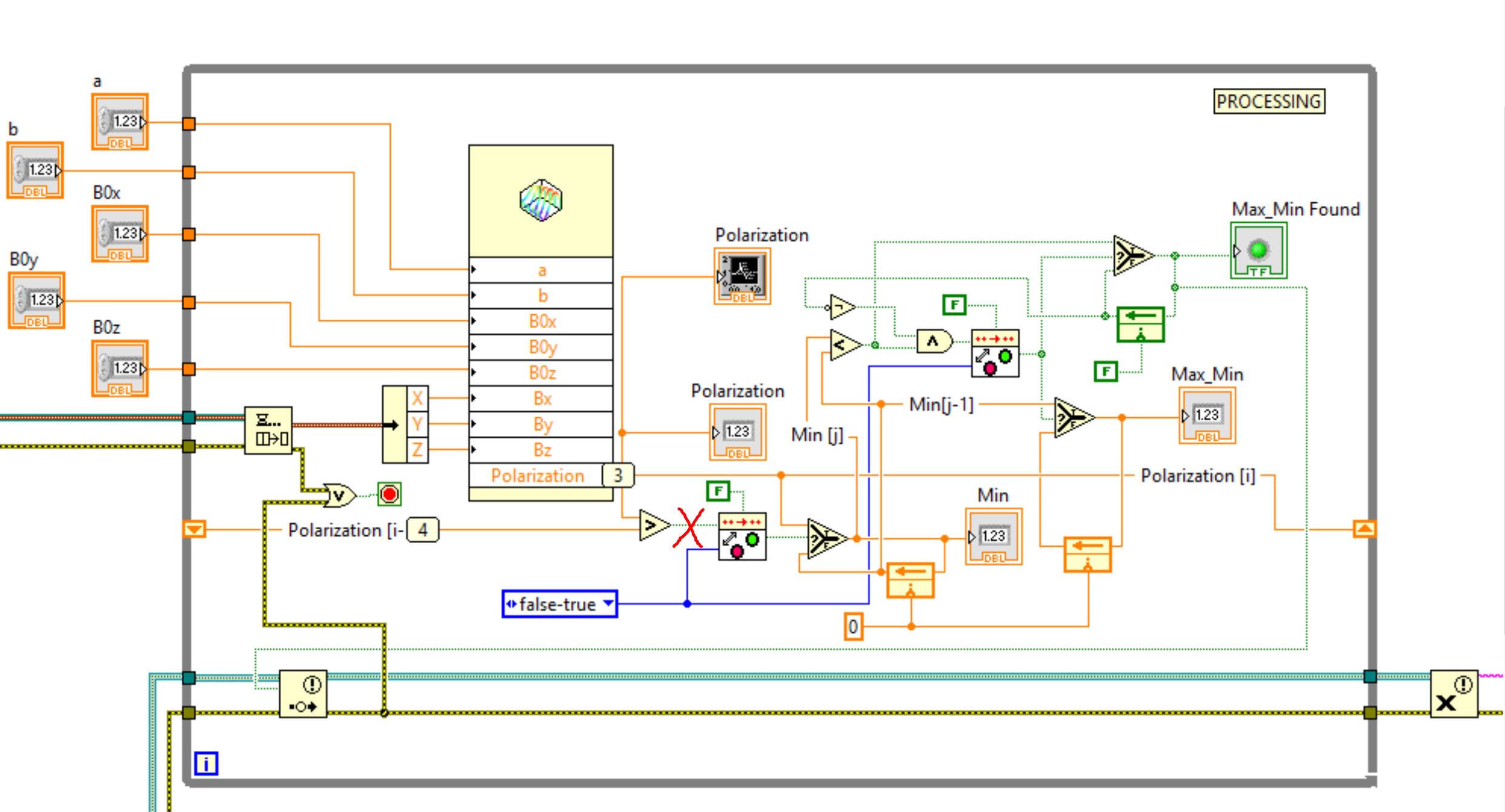
Turn off connection at the start of the VI
Hello
When you start VI adverse action occurs - polarization [i] value is stored in flip-flop (please, see the screenshot below).
There are some tecjnique, that allow to disable a connection (red on the screenshot) for a few moments at the start of VI.
Thanks in advance
Pavel
What the hell...? You are 'i' adding to itself exponentially and compare that to 100... So every time, your code will look like this:
0 + 0 = 0<>
0 + 1 = 1<>
1 + 2 = 3<>
3 + 3 = 6<>
6 + 4 = 10<>
10 + 5 = 15<>
15 + 6 = 21<>
21 + 7 = 28<>
28 + 8 = 36<>
...
91 + 14 = 105 100 >
It's round point rediculously. If this reeeaaally works for you, just on the logic "AND I have 13 >.

Maybe you are looking for
-
I recently updated my iPhone iOS 10 and then again 10.0.2 6Plus - but I encounter the same problem. The ringtones that I attributed to specific contacts do not play, the phone only plays the default ringtone. All ringtones work when I press them, and
-
Unexpectedly Terminal lance by itself
Sometimes - maybe once a day or two - I'll look down and notice that this terminal is running. The window displays just the UNIX prompt, no command or anything. No idea how it's going, but I guess it's related to a program I installed. I thought it m
-
What is a good virusscanner for the mac?
I used mackeeper, but was not happy with it, it made my computer slower. Can what advice you give me on a good virusscanner? GR E Postma, Weesp, Netherlands
-
time I want to copy a disk backup time machine on another nine drive and operate. Can I do this?
Can I copy some time Machines began on a disk Seagate NAS is now almost complete on a new MyCloud WD and operate? A new Macbook Pro purchased 2 weeks ago was the first backup until the older Seagate and I want to continue on a new drive WD MyCloud. I
-
NEITHER USB-6343: erratic low frequency 1 counter measures
Dear members, I'm looking for help with a measure of low frequency counter. I tried to make it work for a week or two, but I keep getting erratic measures. It will read the rpm properly for a second or two and then it will give a ridiculous value o