NEITHER USB-6343: erratic low frequency 1 counter measures
Dear members,
I'm looking for help with a measure of low frequency counter. I tried to make it work for a week or two, but I keep getting erratic measures. It will read the rpm properly for a second or two and then it will give a ridiculous value on the order of 10,000 times the correct value. I can not get a constant value.
I use a DAQ series X NI USB-6343 multifunction with Geartooth Honeywell GTN1A111 sensor. I enclose a sketch of the wiring configuration. I think that it is correct. Sensor output to the door of the meter.
To try to solve this problem, I hooked the sensor to an analog input channel to make sure that I was getting a TTL signal by sensor. I noticed every once in a while I'd see a glitch of little noise in the signal and I guess that's what is causing my problem with the meter. I inserted two waveforms of the sensor signal (one with the clean signal) and the other with the glitch of noise. My understanding of a TTL signal meter channel will examine LO voltage when it is below 0.8V and HI when it is larger than 3.8V. So I really do not understand why these little glitches could be the cause of the problem because they are well below and above 0.8V and 3.8V, respectively. I think that the noise comes from a frequency converter used to drive the engine. I tried the system as much as possible of the Earth.
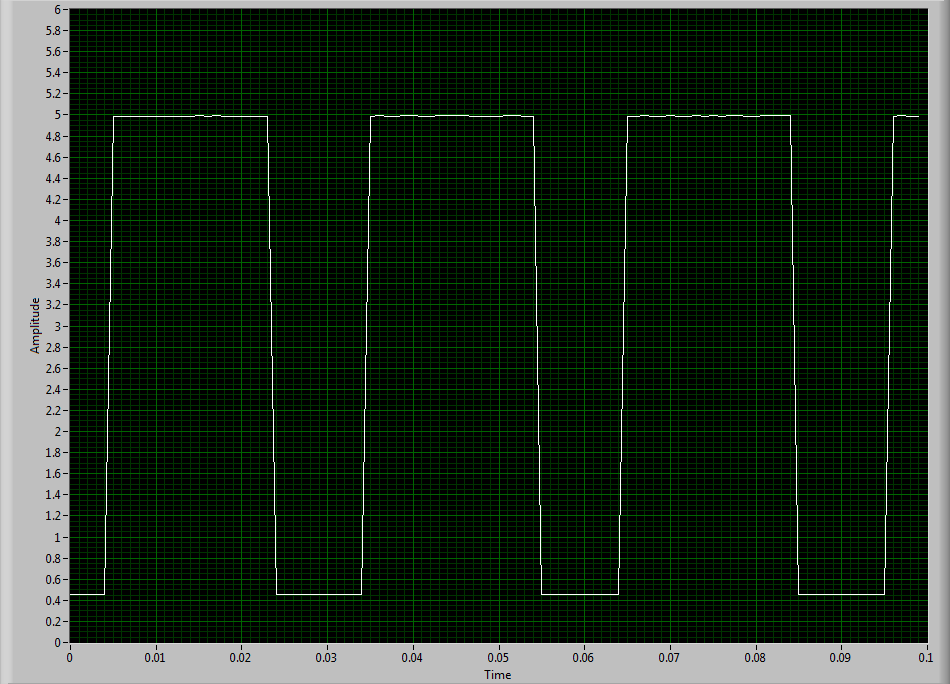
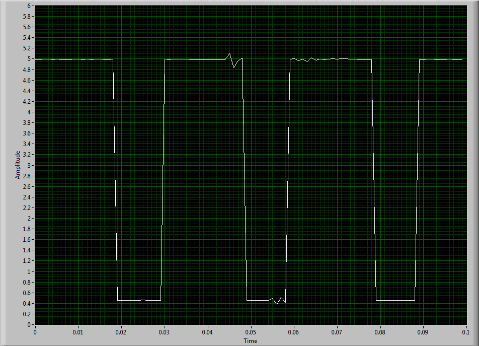
I guess I'm looking for another approach. I could potentially use a digital filter to help with noise? The glitch is in fact the problem or I forgot something. The VI in question is attached.
Thanks in advance,
Mike
Have you tried to set up a digital filter yet? Obviously the seeds are collected as an additional transition (the method of low frequency counter 1 measure the period and then reverse, so a short glitch would record as a very high frequency).
You can enable the digital filter with the following property node:
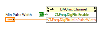
Min pulse width is guaranteed pulse past the filter, so it should be low enough for the real signal is guaranteed to pass through (but high enough so that the glitch is always rejected).
Best regards
Tags: NI Hardware
Similar Questions
-
NEITHER USB-6343 analog and digital grounds
In the manual for the NI USB-6343, it is said that the mass input/output, analog and digital terrestrial are related, but by a small sign. For my application, I am attaching all 3 these grounds to exit the box (I'm tie all areas with physical threads). It is perhaps a silly question, but it's OK to do, correct?
This should be OK unless there are large currents flowing on ground conductors. If you have important currents in the ground, you have other problems that must be resolved before you connect the DAQ hardware.
Lynn
-
NEITHER USB 6343 negative DC voltage after power function generator
Hey all,.
I'm having a problem with my DAQ. I'll generate a square wave in Labview with a generator function and that the output to my DAQ. The function exited through the acquisition of data very well; However, when the production is stopped, a negative voltage remains equal to the amplitude ("drawing" below). This happens if I use the express VI DAQAssistant, or manually create the channel, generate the function and the function read/write on the channel. This tension continues even after the VI is finished running. The only way to get rid of it is physically cut the DAQ and turn it back on. Any thoughts on why this might be, or how to fix?
Start VI
____|____|____|____|____|____|
____|____|____|____|____|____| _ _ _ _ _ _ _ _ 0V
____|____|____|____|____|____|____________ - A V
____|____|____|____|____|____|
End VI
Tom
I thought about it. I had to add some more to the clock. I had added a data point in the table of waveform which was written for the acquisition of data because the timer wrote n samples, instead of n + 1

So, to recap: I pulled the table leave the waveform data, inserted a '0' at the end of the wave, reintroduced the data of Y in the form of wave and incremented to the timer of a sample (because I added a sample for waveform data).
-
NEITHER USB 6008 voltage offset using CSR and measurement of diff.
Hi all
I am currently trying the NI USB 6008 housing and I'm getting problems when reading voltage analog using CSR or differential.
So basically, what I want to measure is a PWM signal (0 to 12V), which is divided by a divisor of tension (by two). But instead of measured 0V and 6V
I am in a position a constant 0.8V and approximately 3V.
On the side of digital data acquisition, I give you on impulses for the SSR... and it works fine.
I connect it that way: http://digital.ni.com/public.nsf/allkb/95CC0CB11D7DF3D18625712E000C4ABD?OpenDocument
Would apreciate any help
Best regards
EDIT: Attached graphics acquired are
What is the impedance of your voltage divider? The input of the USB-6008 impedance is not very high. If the impedance of the partition is large, it could cause the effect you see.
Lynn
-
Frequency counter measurement crashes when you're away point zero (NI USB 6343, error-200284)
Members of the Forum,
I have problems with a measure of the frequency on a DAQ Mulitfunction of NI USB 6343 X series. I use the meter 1 (door axis for frequency signal, PIN to DGND 82 77). The couple HBM T10F flange that I use (powered by a power supply of 24V) emits a signal of frequency between 5000 and 15000Hz with 10000Hz being the zero point. Couple flange has a capacity of 5kN.m (15000Hz = 5kN.m; 5000Hz = - 5kN.m).
I have been using the VI attached for a few months now without any problems. Now, the VI works fine as long as the couple remains inside a few hundred Hz of the zero point. However, when the frequency increases further reading couple begins to freeze and finally I get either of these two errors:-200279 or-200284 related samples is not not available. I noticed that the light on data acquisition close compromise during these periods of frost.
Here is an example step by step my problem using cal shunt of the flange of the couple:
1. I have run the VI and couple bed properly around 10000HZ (Active light, indicator light ON)
2. I have apply the excitation of 5V to the shunt cal and frequency climbs to about 50% of the ability to couple brackets (as it should)
3. as soon as I remove the excitement 5V playback freezes and the light on the acquisition of data.
4 if I apply the 5V once again, until the timeput occurs, the led turns on and the acquisition of data reads the signal correctly.
This type of problem would be more DAQ-related or is it the flange of the couple itself.
Thanks in advance,
Mike
Solved.
I did some troubleshooting this morning and it turns out that the vibrations of the system had not tightened a screw that was connector to the stator flange torque causing a bad electric signal of the torque flange itself.
Everything works fine again.
-MB
-
Sample USB - 6343 Counter clock
I use a USB-6343 CTR0 to measure the angular position. I expect to ~ 1 million encoder pulses (or account) per second. What USB-6343 clock signal would be preferable to use the counter sample clock?
Dar Hi,.
At what resolution do you need measure the angle?
One of my colleagues has compared the maximum sampling frequency on the counters of series X USB to be approximately 8 MHz for a single channel, continuous operation for 10 minutes. However, if the signal that you intend only generates pulses at 1 MHz, 8 MHz rate seems unnecessary because you will receive the same reading several times.
Concerning the two methods you mentioned, either would not be possible:
(1) you could count the external signal and sample at regular intervals. For example, if 10 kHz sampling you'd expect to see ~ 100 strokes per sample if clock signal is 1 MHz.
(2) you can also use the meter to count a time base internally (for example 100 MHz) and the sample out of your external signal. Thus, during a period of your external signal, you expect to see 100 graduations of the time base.
It seems that what you're trying to do is to measure the frequency of your encoder at regular intervals. To do this, I suggest you actually a variant 3. X series cards support a measure of frequency clocked for example (see the X Series user manual). The card has two occurrences of the external signal as well as occurrences of the internal time base known and uses it to determine the frequency. The one caveat is that the signal you are measuring the encoder must be at least two times faster than the sample clock signal. I suggest to use Freq Out or another counter to generate the sample clock.
Best regards
-
Hello
Could someone give me some information about whether it is possible to use the
NEITHER USB-6501
As a generator PWM to control the dimming of 18 power LED function?
calendar is not so relevant and if the pulse width can be controlled in the PC itself application the purpose would be financed
Hello ONavarro,
It is technically possible, but please note that USB-6501 as only software clocked e/s digital (e/s static). In other words the duty cycle of the PWM periodocity Ant you want to generate will be determined by a loop software, so depending on your system and the USB bus. I think that you will not be able to get a better rate of loop (ability to change the State of a digital line) less than some milliseconds (depending on the system).
By example, if the loop runs at 5ms, and I want 10 steps in my PWM, this means the period will be 50ms, therefore a 20 Hz base frequency. If you can't reach 1ms, you will get 100 Hz. If you want more than 10 duty cycle value, you reduce the frequency.
And it is NOT stable (loop software 5ms, first delta 5.8ms, then 4.9ms, 5.1ms, 6.7ms, and so on), because it is based on the software. If you need something stable and faster, choose a device with hardware synchronizing.
Best regards
-
NEITHER USB-6008 connect to thermocuples and pressure sensors, control valve
I am endevoring to build a gasification plant biomass for bench scale test process control plans. NEITHER USB-6008/6009 will be adapted for use as a data acquisition. I'll take RTDS, thermocouples and pressure sensors. I don't want to use industrial automation controllers. It is also possible to use the channel of analog output for sending signals to a control valve position (using sufficient current/voltage between the two drivers).
(1) OK. I just wanted to be sure that you were aware of the potential dangers.
(2) an RTD is a resistance that has small changes in resistance per degree of temperature change. To measure that you have need of a current source and a sufficient resolution in order to detect small changes. At 25 degrees C a typical RTD is 109,73 ohms and resistance ohms 0.38 per degree changes. If you had 1 my crossing this RTD voltage through it would be 109,7 mV and the voltage change of 0.38 mV by degree.
The resolution of the 6008 on the most sensitive range is 0.49 mV > 1 degree. The accuracy of the 6008 is 1.5 mV typical.
For a Type K thermocouple, voltage at 25 degrees is 1.407 mV and change by degree is 39 µV. Millivolt solving half of the 6008 translates into about 12 degrees.
If you need a source of excitement for RTD and a kind of amplification for thermocouples and RTD before she would make any sense to try to use USB-6008.
(3) I have not used anything except LabVIEW with DAQ devices and drivers. I think DAQmx can be used with MATLAB and other languages.
(4) the 6008 is the low range made by NOR. You will need to go to a more expensive camera or add signals conditioning circuits. Talk to your representative OR assistance in the choice of a suitable device.
Lynn
-
Simple examples of analog output USB-6343
I've tried passing by 'find' examples and does not know how to find what I want.
I'm doing a simple analog output on a USB-6343. Examples of waveforms say they work with the USB-6343, but I really don't want a waveform, just analog of output does not exceed 10 Hz speed of renewal. Some of the more simple examples show that they work with the pcie-6343 but do not list USB-6343.
I worked with USB-6009 in the past, but when I try to use an analog output task that uses 1 sample on request, I get the error "not buffered operations clocked by the hardware are not supported for device and channel type.» Set the size of greater than 0 buffer, do not set up the timing of the sample clock or the value Type of sample On Demand time"
I tried samples N, 100 samples to write to 10 Hz - the same error. Samples of continuous - same error. 1-sample - timed HW - same error.
There is a series of examples of I/O for the X series? Is it possible to search the device examples rather than go through all the examples and by checking the list of devices individually?
Is 'size of the buffer' the 'writing samples"in MAX?
After contacting the support I was provided with the names of the more simple examples for analog i/o:
Analog output-Gen power Update.vi
Analog Input-Acq & chart voltage-Int Clk.vi
They are found in the getting started screen of
Click 'Find examples' near the lower right corner
Filter the results to material by clicking on the menu drop down for the material in the lower left corner and selecting USB-6343 (only connected equipment will be displayed)
Don't forget to check the box "limit results to material" below.
In the center pane, double-click 'Material Input and Output'
Double-click DAQmx
Path for the analog input - double-click Acq & chart analog measures - double click on tension - tension-Int Clk.vi
Double click on analog generation - double click on Power - Gen Update.vi of analog channel output voltage
The examples are for the single data point. Samples and exit multiples are produced by putting the writing or reading VI inside a loop. The beginning and the clear functions should be out of the loop.
Additional information, I need technical support was how material-filter results and identification of more simple examples which were not obvious from the examples of names.
-
Memory running at a lower frequency
I recently added 1 GB 667 DDR2 ram to my office, a1514in Pavilion (previously 1 GB 667 stick). But now the bios is show my DRAM frequency as 266 MHz (PC2-4200), these are the cases with different configs:
-If I put only OLD stick of 1 GB 333 MHz (PC2-5300) show
-If I put only NEW stick of 1 GB it will show 266 MHz (PC2-4200)
-If I put both OLD & NEW 1 GB stick will show at 266 MHz (PC2-4200)
Has also tried different machines slot but no use (I have only 2 slots and memory support for my system max is 2GB BIOS version 3.24)
I am not able to understand what the problem is. In CPU - Z under the SPD, the two sticks are showing similar settings (I have not so good idea on these parameters). Please help me why the new RAM runs at a lower frequency... What should I do?
Hello Khot
What is the model of your Samsung of RAM stick?
According to the specifications of your motherboard RAM supported, speed isn't PC2-4200 and PC2-5300.
Another thing, usually by mixing different RAM is a bad idea. The reasoning is that each RAM stick is intended to be run at a specific frequency, timings and voltage. If two sticks use different frequencies, timings, tensions that the BIOS will be all run the highest common denominator. In your case, that your new stick of RAM PC2-4200 and, therefore, the BIOS reads your second stick is run at the same speed for stability purposes. -
Satellite A215-S7444 - name of the low frequency amplifier
I need to know the name of aplifier of low frequency in a Toshiba Satellite A215-S7444 main laptop Board. I have problem with my speakers because they beep. And the problem is with amplifier speakers.
Please tell me the name of this integrated circuit.
Hello
I think that no one here can answer this question because it s only a user to user forum and I have never seen anyone from Toshiba here. I think that this question can be answered only authorized individuals.
I recommend you contact an authorized service provider. Technicians could answer this question and help you get a new spare part.
Good luck!
-
low frequency with labview 2010 auto and agilent 35670a
Hello
I work on the automation of low-frequency measure a 35670A Agilent. I currently did a program that allows a measurement with an average of FFt given a frequency bandwidth and frequenct from beginning, see picture attached, but I try to measurement of spectrum using this power VI (
 ), but unfortunately I can't seem to find how to convert a signal from my block diagram below in order to send the input signal power VI above spectrum X no indication or help will be appreciated.
-
synchronize the outputs digital AND digital NI USB 6343 entry
Hello
I use NI USB 6343 to fly 1 TTL devices. This device can also produce a TTL signal to indicate if the door is opened/closed.
I use digital Bool 1 line 1 Point. I was able to reverse the opening/closing of the door on time. But I would like to synchronize the DI and DO it right.
I tried to throw in the clock aboard, but he failed.
Is it possible to synchronize the DI and DOI onbaord/hardware clock?
Any idea will be great!
Thank you!!
Hello
Synchronization of your tasks of DI and shouldn't be possible with your device. You'll need them timeless has a clock that is usable by both. This information is available in the X series user manual
http://www.NI.com/PDF/manuals/370784f.PDF
PG 6-9 and 6-13You can also find information and examples of synchronization of the various tasks in the article below.
http://www.NI.com/product-documentation/4322/en/Good luck
Eric
-
Meter very low frequency using PCI-MIO-16-4
Hello
I am trying to use a card PCI-MIO-16-4 with BNC-2090 to CI FREQ. Because the sometimes less than 1 Hz frequency of our leaders, or even no time measurement taken, the vi program always shows "Error-200527" and tells me that the min frequency must be greater than 1,192 Hz. If this card cannot measure very low (even zero) frequency in time measurement taken? If it is possible, how? Could you show me some examples? Thank you very much.
Damien
What method of measure do you use to measure your rate? You are able to assign at least 0 (default) to 2 that would be the rounded version of 1,192. Alternatively, you can try to use one of the other methods to measure and see if that helps. All these values can be set with the channel to create VI.
-
Measurement of temperature using NI USB-6343
Hi all
Someone at - he temperature ever measured using an NI USB-6343 or something close to it? Encountered problems?
I was reading on the device and it has been suggested that the conditioning of signals may not be required, and I'm a little worried...
Normally I use a DAQ Agilent but this specific project, I'm working on that will require a unique moment and USB-6343 handles a majority of my problems along will be many examples of coding.
-scrider
Scrider,
You want a device that has USB connectivity like the 6343? If so, we have several hardware based USB DAQ for thermocouples. The links below will show 3 devices, we have:
http://sine.NI.com/NIPs/CDs/view/p/lang/en/NID/208177
http://sine.NI.com/NIPs/CDs/view/p/lang/en/NID/201881
http://sine.NI.com/NIPs/CDs/view/p/lang/en/NID/207471
Now, I know that some of them will probably not ideal for your app, but I wanted to just give you options. It also depends on how fast you want your sample rate is. These devices are specific for the use of thermocouple, but you can still use them (excluding the tc01s) for voltage readings. I hope this helps!
Maybe you are looking for
-
Hello I just upgraded to macOS Sierra and built-in Cisco IPsec VPN no longer works. When you try to connect, I get a "cannot validate the certificate of the server. "Check your settings and try to reconnect" error message. I use Cisco ASA with self-s
-
Tecra M1 - SD cards with greater than 1 GB capactiy?
I have a Tecra M1, the SD card reader is limited to cards up to 1 GB of capacity. Y at - it a software update available to enable higher capacity cards to be recognized?
-
Need to Win7 64 bit for Satellite A300D display driver
Should which driver I use for my old A300D running on W7 64-bit? Can not find anywhere...https://drive.Google.com/file/d/0B9Ls81E7uVtLb1l2V09ENFZyOTQ/view?USP=sharingTHX!
-
Pavillion 32 2K: When can I expect the New 2 K Pavilion?
Hi all I am interested in buying a new screen for my HP computer, when I came across a post about a new 2K Pavilion that apperently is coming (see this link: http://www.tomshardware.co.uk/hp-pavilion-32-inch-qhd-display, news - 52907.html ). Anyone k
-
Why windows shuts my photoshop cs5 on launch
MY PHOTOSHOP PROGRAMS CS3 AND CS5 ARE STOP UNDER LAUNCH A WINDOWS WINDOW COMES UP TO SAY THERE IS A PROBLEM, BUT HELP DOES NOT WORK WHY?