FPGA target host DMA FIFO multi-channel
Hi people,
I have a little trouble to collect my FPGA application data. The control of my FPGA application loop is running and read data from set point between a host and target FIFO to a period of 50 uSec. I run a separate loop to write data collected form two channels in a target of FIFO host over a period of 1000 uSec. I'm taking the data from both channels and its reading on the host in bundles of 500 data samples. The first problem I have is that my method of reading times unless I put my data acquisition loop to run at a much slower pace. My FIFO depth host side is 60000, almost as large as the total number of data samples that I expect to collect in total.
I have another problem when trying to write the data to a table. Even if my method of reading does not expire, I don't think that will record the first beam of data that are read. I've initialized an empty table outside my acquistion of the side loop host and used the table VI build to take the current data set and add it at the end of this table. I then store in a shift register and pass it in the next iteration where I try to join the new data set to the old and so on. I expected to get a table with all the data, but as I said I'm only collecting the first set of 500. I wonder if my program structure is correct. Any help anyone could offer would be greatly appreciated. I have attached a few pictures of my reference request. Thank you.
Hi Daniel,.
Thank you for your response. I think I found a solution to the problems that I had. Looks like it was a combination of a couple things. First, the data acquisition loop was running not until the movement was already over since I plugged the condition to stop the loop of writing deposit directly on the data read loop. This problem has been fixed by creating a shared variable for the stop condition and it wiring to two loops independently. This explains why I got only the first set of data, as it was stored in the FIFO until the end of the movement. However, the FIFO of feedback was still time. Before attaching the stop condition error, I placed a probe on the "items remaining" wire of the read method and concluded that there was only 1023 elements (the depth of the FIFO on the side FPGA) even if I set the FIFO depth host side to 60000. "» I realized it was originally due to the Read method not called for the first time until the end of the movement. Although the problem of break for most fixed condition this problem given that the Read method was now called during the movement, I decided to take a preventive measure and calling the 'Start' before the movement FIFO method is started just to make sure that the memory of PEP on the side host is available immediately.
So yes, it turns badly I put sync settings have been well after all. Good call on the reversal of the order on the Array function to build. Oh, and I also had to move the waveform diagram to until the table is built so that it is not Replot the old data on top of all the new data it receives. On the same note, I moved to the indicator in table at the end outside of the loop of reading. Thanks again for your help.
Kind regards
John has
Tags: NI Software
Similar Questions
-
Target to host DMA FIFO not compensation when they are arrested
I use a PXI-7841R (Virtex5) and 32-bit data to the host via DMA FIFO transfer. When you read the FIFO on the host for the first time, the data are "stale" (which means that it is not what is currently coming in the FPGA, but what came in a few seconds ago stale). I tried both a stop and a configuration for clear memory FIFO before I use them. Documentation on one or both of these so-called clears the target and host the FIFOs. Does not help in both cases. With readings of the second and the following, FIFO has then 'valid' (same data as it appears on the FPGA entry node). What is curious is that each reading exactly the same thing:
- Stop the FIFO (must erase all data)
- Elements of reading 375 of the FIFO. (repeated playback of the FIFO)
Also interesting: FPGA FIFO is implemented for 255 elements. The first 255 items host-side contain the data "stale" on the first reading. It reminds me of the never erased FPGA FIFO.
Answered by support OR. The documentation for the FIFO, stop and configure FIFO is in error. Cars of documentation will be written against them.
Solution:
These methods remove only the FIFO on the side host. Data FPGA FIFO must be read following until no element.
-
Number of items in the target to host DMA FIFO
Hello world
I would like to transfer a set of datapoints of an FPGA to a RT-host controller using a fifo DMA. If I use the 'Get number of items to write' function on the FPGA target, can I get the total number of items in the two buffers, or just one on the FPGA target?
(see http://zone.ni.com/reference/en-XX/help/371599H-01/lvfpgaconcepts/fpga_dma_how_it_works/)
markus_a wrote:
If I use the 'Get number of items to write' function on the FPGA target, can I get the total number of items in the two buffers, or just one on the FPGA target?
The FPGA will have no idea how big the DMA is on the side of the host. He can't see his own DMA buffer.
Get the number of items to write just tells you how many items are not used by the DMA (ie the number of items that currently write to the DMA without waiting for items to be offered by the host reading).
-
Target to host DMA FIFO - actual number of items
Hello
I have a target of FIFO of DMA host using memory block. Under FIFO properties, "the actual number of elements" is indicated as part of 1023.
But when I wire a remaining indicator to the 'elements' of FIFO in the host of VI, said 16384 elements. And I read a lot of part of the FIFO.
Why is the actual number of items that much more?
The data type is 32. And I have a high-7965R FPGA.
See you soon.
There are two different buffers for the FIFO: one on the host, the other on the FPGA. Data is copied from one to the other. It may be more space allocated on the host, because there are more memory available here and the loop of the host, probably runs more slowly than the FPGA. You can set the host using a node to invoke FPGA FIFO set the buffer size value.
-
Hello
I have the next vi FPGA and RT vi (joint). I'm trying to transfer data from the FPGA to the RT vi (using the target to host DMA FIFO), then to plot the data in the RT vi. The signal that I take analog input also is a 10 Hz, 1 well module 9215 V sinusoidal amplitude.
However, in the RT vi, I get only one exit fluctuating, with only the values 0 or 1. Also I see no time-out that happens with the RT parameters vi as: 'TimeOut = - 1' and "Count (uC) = 25".
Why would this be happaning?
Thanks in advance...
Mandar-
Hi Mandar,
Not with 8.6. You told me 8.5 documentation (I didn't know you were using this version). Take a look at the following article; It should solve the problem that you are facing:
How can I transfer my data to fixed-point using a FIFO in LabVIEW?
-
How to choose the maximum number of items for DMA FIFO to the R series FPGA
Greetings!
I'm working on a project with card PCIe-7842R-R series FPGA of NOR. I use to achieve the fast data transfer target-to-host DMA FIFO. And to minimize overhead costs, I would make the size of the FIFO as large as possible. According to the manual, 7842R a 1728 KB (216KO) integrated block of RAM, 108 000 I16 FIFOs items available in theory (1 728 000 / 16). However the FPGA had compilation error when I asked this amount of items. I checked the manual and searched online but could not find the reason. Can someone please explain? And in general, what is the maximum size of the FIFO given the size of the block of RAM?
Thank you!
Hey iron_curtain,
You are right that the movement of large blocks of data can lead to a more efficient use of the bus, but it certainly isn't the most important factor here. Assuming of course that the FIFO on the FPGA is large enough to avoid overflowing, I expect the dominant factor to the size of reading on the host. In general, larger and reads as follows on the host drive to improve throughput, up to the speed of the bus. This is because as FIFO. Read is a relatively expensive operation software, so it is advantageous to fewer calls for the same amount of data.
Note that your call to the FIFO. Read the largest host buffer should be. Depending on your application, you may be several times larger than the size of reading. You can set the size of the buffer with the FIFO. Configure the node.
http://zone.NI.com/reference/en-XX/help/371599H-01/lvfpgaconcepts/fpga_dma_how_it_works/ explains the different buffers involved. It is important to note that the DMA engine moves data asynchronously read/write on the host nodes and FPGAs.
Let me know if you have any questions about all of this.
Sebastian
-
I want to transfer data to my FPGA using a DMA FIFO. The FIFO is 1024 elements, but can I write bigger than that of the side pieces PC? I don't know if the PC actually allocates a larger block of memory for this purpose?
I'm sure that you can set DMA on the side host is greater. There is a node of configuration DMA you can use host-side to define the size of the FIFO on the side host. The size is set in the hardware on the target side.
-
SMU FlexRIO DMA FIFO host read the FIFO overflows broadband bandwidth/DMA issues
I'm working on an application that uses 2 modules FlexRIO, and 2 LVDS digital I/O adapters. I'm driving each of the SDC A/SDC B ports on LVDS 16-bit data at 50 MHz adapters. The FlexRIOs are expected to receive the data and write down them on four targets-to-host DMA FIFO (one per connector SDC), or two by FlexRIO. The host reads the FIFO and brings together a series of tables each FIFO output 2D. Ultimately, the individual tables (we're each a quarter of single image) will be assembled in simple images, but I haven't gotten that far yet.
The duty cycle for the data is about 80% (in other words, I'm only transmit data to the FlexRIOs 80% of the time, the rest of the time the transmitters are disabled), so the flow is about 80 Mbytes/sec/port total invasion, or 320 MB/s on the four FIFOs DMA. I find that the acquired data gaps sometimes inside that line up along the length of the material part of the DMA FIFO in FlexRIO modules. In other words, if my memory FIFO DMA are set to 65535 length, I'll see a break in the data acquired at the word of data 65536th. Data is a waveform of sight, which is essentially just a counter, so it's easy to see the break in the model. For the words of first 65535, adjoins the data, then from Word 65536 model is discontinuous and starts counting again from there, contiguously. At the beginning of the acquisition, the FIFO is erased: the beginning data read from the FIFO is always aligned correctly, so I know that the process starts at a good point.
The error is not always the case: sometimes I get continuous data through the point 65536. In addition, the error occurs independently between the four FIFO: on a particular race, a FIFO could have data of interest and some bad. Rarely, all four FIFOs have good data.
The fact that the gap of the configuration is to the point even the depth of the FIFO DMA tells me that fills the FlexRIO FIFO, the FPGA hardware without the system managing to move to read, which means that the data gets dropped during the period that the FIFO is full. Then transfer to the host comes into action, there again is the space in the FIFO, and the data is once more contiguous in FIFO memory for a large amount of data (I have not yet tried to locate a second gap in the data of a single acquisition). It seems therefore that the host doesn't have enough bandwidth between the FlexRIOs and the host of RAM to prevent the filling FIFO, or comes along some software process on the host that is temporarily stop the ability to instantly transfer.
Are at - it a specification for the SMU flow system that would indicate that we are trying to use too much bandwidth? Or are there priority controls on DMA FIFO that would allow us to raise the priority of the FIFO transfers as they are guaranteed to go in preference to other system tasks?
System Specs:
SMU-1075 chassis
SMU-8135 CPU
2 SMU-7962R FlexRIO modules
2 digital i/o modules of NOR-6585
LabView 2012 32-bit SP1 version 12.0.1
A suggestion of an applications engineer of NOR and some experimentation has solved the problem. It turns out that I was calling the method FIFO of DMA stop just before the outbreak of the transmission of the data via a control for the FPGA FPGA VI. I did this in order to clear the FIFO before you begin data acquisition, but I didn't know that this method disables also transfer data between the memory FlexRIO and host. Following this call, I trigger the FPGA code to start filling its FIFO and then begin reading. Calling the Read of FIFO of DMA apparently light up the transfer back, but it seems that the host VI has been randomly slow down enough to move to the bed such as filling the side FlexRIO FIFO and dat would be lost. I changed the host VI to insert a FIFO method call start before the trigger for the FPGA signal, and the problem is now gone.
-
Hi guys!
I am writing here after many days of attempts without success...
My request is 'simple', send data from the Panel of Labview RT within a DMA FIFO target host. Then the FPGA core receives data and imported through a knot of VHDL processes, and then after the data is pointing to the Labview RT through a target to host DMA FIFO.
I tested my node VHDL simulation mode in Labview FPGA where data sent by a target scope THAT FIFO and just work fine.
But when I try to run the node VHDL in the real target with data from the RT by DMA FIFO basis, it won't. I already do some checks:
-Data are properly sent through the host target DMA FIFO;
-The data are correctly received in the FPGA base;
-The data are correctly sent to the node VHDL;
-Result of the node VHDL are correctly sent to the heart of the RT through the target to host DMA FIFO;
-Result are correcly received in the heart of the RT, , but the result is false and absurd. But I have proof that my node is semanticly correct with my mock test
So my question: are there reasons to see my work VHDL nice knot in simulation mode and not in mode real target with data from the base RT by DMA FIFO taking into account data Transfer between DMA FIFO work well in both sides? Is there some sample available with data send RT FPGA-based via DMA and data processing with a knot of VHDL and returned to the RT kernel to inspire me?
I can't post my screw here because I work for a company, I use a MyRIO with Labview FPGA 2014 target.
Thank you guys! I am available for some details on my implementations.
Afghow.
Hey!
Thank you for your answer but I solved my problem. Indeed, at first, I tried to make a knot of Combinatorics (without clock) pure, but the problem seemed to come from that.
I modified my node in order to incorporate a clock, according to the prescriptions of this white paper: http://zone.ni.com/reference/en-XX/help/371599K-01/lvfpgaconcepts/ipin_prepare_ip/ . And now, every thing seems to work well.
The question remains why the combinatorial node has worked in simulation mode en not in the actual target?...
But for people with the same problem, I suggest add them a CLK and check an edge of entry with rising_edge (CLK) and if it does not, add an input signal to check if the input signals are valid or not.
Afghow.
-
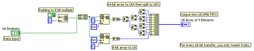
How can I transfer more 64-bit data to the target host?
Hi all, I currently use fpga PCIe-7851r card to drive my camera. There were 64 lines to remotely control. So what I did generates the commands on the host pc and transfer it to the target via DMA FIFO. The data type of the FIFO is U64, i.e. each digit control 64 DIO lines. But the issue becomes complex when I transfer 66 command-line. I tried to create 2 FIFOs, but I can hardly do the 2 Sync FIFO.
I think I might be able to create 2 tables U64, one contains the original 64 line, s command and the other for the 2 line (a loss) information. And then I have them interleave in hospitality and decimate them in the target. There should be enough cycles to it. But I don't think it's a good solution. Is there a better method? Thank you.
LabVIEW 2009, Windows XP, PCIe-7851R
Kind regards
Bo
Using the techniques highlighted in this tutorial:
http://zone.NI.com/DevZone/CDA/tut/p/ID/4534
You can use code like this:
-
Transmission of data to the host of RT to the FPGA via DMA FIFO
Hello
I try to write data from a host of RT on target FPGA using DMA FIFO and then process these data and read then return of the FPGA target to the host of the CR through an another DMA FIFO. I'm working on the NI SMU chassis 1062 q, with the built-in NI SMU-8130 RT controller and target FPGA NI SMU-7965R.
The problem I face is that I want to send three different tables, two of the same size and the third with different size, and I need one more small to be sent first to the FPGA. I tried to use encode dish with two executives in the FPGA VI. In the first image, I read and write the first table in a while loop which is finite (that is, a finite number of iterations). The second frame contains the process of reading and writing the second two tables (of the same size) in a while loop that can be finite or infinite (depending on a control). The problem is that it does not work. 2 arrays are displayed on the front panel of the RT VI host and works well, however, the table that should have been read in the first sequence does not appear on the front panel of the RT VI host. It is not sensible because if it is not passed from the host to the fpga and vice versa then the second image should not have been executed. Note that I'm wiring (-1) for the time-out period to block the while loop iterations until the passage of each item is completed. So the first while loop has only 3 iterations. Could someone help me undersdtand why this happens and how to fix this?
I enclose a picture of the host and the fpga vi.
Thank you.
If you vote for my idea here and it is implemented, you can even omit the loop FOR fully.

(I also propose the RE / IM divided inside the loop FOR and perform operations on complex table before the loop the transpose and reshape .) In this way, you only need one instance of these operations. You might even save some unnecessary allocations table in this way)
-
How is managed using DMA FIFO (target host) host matrix
Hi people,
I'm trying to pass an array of values of the host to the FPGA using DMA FIFO. Let's say 20000 items in the table. My FIFO host side can contain only 16000 items or almost. The data will be written element by element regardless of the size of the table or do I need to partition the table in small paintings before writing the FIFO method? Let's say that I write for the FIFO with berries small, 1000-element. The FIFO will read 1 element both of the side FPGA so the stream is blocked until I have at least 1000 free items on the FIFO method write, how he writes every 1000 the next setpoint at the same time? Or target values will be written permanently as soon as the individual elements are erased by the number of available items to write?
Hi Nathan,
Sorry for the late update, but I just thought that I should follow. I followed your advice and try it tested just for me (I probably should I have done it before posting). Turns out that the data table will write even if there is not enough empty elements to contain the table in its entirety. However, it always crashes until enough information is read and erased from memory on the side FPGA for the whole table. So if it's data that are constantly being played, it's always better transmitting data through in the form of smaller tables if you do not want to increase the amount of memory FIFO host OCCUPIES on your system. However, if you can afford the memory while you mentioned, you can always increase the depth of the FIFO on the host side. As I understand it, try to write more big berries to a host to target FIFO buffer does not diminish overhead costs (as is the case with a target to host FIFO) as it still passes an element at a time to the FIFO of FPGA-side without worrying.
Thanks again for your help.
Kind regards
John has
-
FIFO of DMA beteen switching channels after sends FPGA
Dear community,
I read 8 AI with the CRIO high frequency corresponding to 8 sine waves of resolvers. Also, I do operations in the FPGA and passing to the RT host 2 FIFOs. One is called resolvers with these 8 channels and the other is called speed and accel. who has 12 channels with 4 angular positions, 4 speeds and accelerations 4 in that order. When I read the two FIFO with the host I wait for the PEPS have enough elements. I also put the time-out of the FPGA-1 to avoid problems altought I know very well what to select. The problem is that when I read with the host, the channels do not keep the original order I used to assemble in the FPGA and also it is possible to appreciate swithings between channels every few seconds so that the information is not uniform and robust. It is not possible to use the information if the channels do not change their relative position.
I have ideas to solve this and incrementing the RT frequency because it goes to the maximum of 60 Hz, where I expected much more.
Thank you very much.
Concerning
Enrique
EnrikDS wrote:
Hello
attached are two images to explain what settings I use to configure FIFO. We can concentrate on speed FIFO:
-Depth confgured to: 120000
-Number of items in a read statement: 1200
The FIFO can also be configured in the Project Explorer, in fact, I'm not sure if the depth setting configured in the block diagram means the same as the parameter
"Asked number of items" that appears when you double-click in the FIFO to the Project Explorer, the value is 4095. Other values are:
-Target to the host
-Data type: FXP (64-bit, 32-bit)
I hope this helps. Thank you very much for your support.
Enrique
When you configure the FIFO since the project you define how much space FPGA to be used for the FIFO for buffering before data are duplicated in the FIFO of RAM defined by the property node.
Have you tried to set the expiration time of the FPGA FIFO entry to 0, that would be a FIFO with loss. You can use the FIFO. GetNumberofElementstoWrite to ask how much space is in the FIFO and write only when you have 8 to 12 free items.
-
Using TWO DMA FIFO target host
Hi, I use a unit 9004 cRIO for the purpose of data acquisition. I try to get signals analog (NI 9221) and CAN (NI 9853) modules and transfer them from the fpga VI VI in real time using DMA FIFO, that is to say, target to the host. I thought I should use 2 DMA FIFO, one for analog and CAN signals. When I tried to put them, I put the two FIFO in the same loop. I don't know if that's the only reason, but it would generate overflow error 50400. When I removed a FIFO and put the single FIFO, it worked fine. So, I thought they must perform independent while loops and implemented two while loops that would be run in parallel. And it worked. I don't know if this is how it is supposed to work? Is this that FIFO DMA should be run in parallel loops? Are they written in such a way that the FIFO function cannot be called for more of an instance in the same loop? This seems odd.
I should also mention that I reconnected it the wires on analog, digital and CAN modules before putting them in separate loops. And I know for a fact that the FIFO CAN show underflow error if the entry of the threads on the port CAN are not connected. Also, I don't use mode Scan Engine (I think that its not available in 9004)
You are right about the 9004 and Scan Engine - or the lack of support, I say... Regarding the error of underflow, this behavior is expected when you have two Scriptures DMA FIFO the same loop. What is happeing, it is that the two FIFOs write in true parallel. Thus, when you write to FIFO1, FIFO2 expected FIFO1 finish. Then, when you write to FIFO2, FIFO 1 must wait on FIFO2 and the while loop to reiterate before he can write more data. So, on your VI in real time, if you try to access one of these FIFO that has no data in there because it is waiting to write the next block of data, then an overflow error will happen.
When you separate the two FIFOs, both can run independently from each other and write at a much faster pace. In this way, your FIFO reads on the realtime VI will not be stuck in a State of negative overflow where a FIFO is waiting for data queued.
I hope this helps!
-
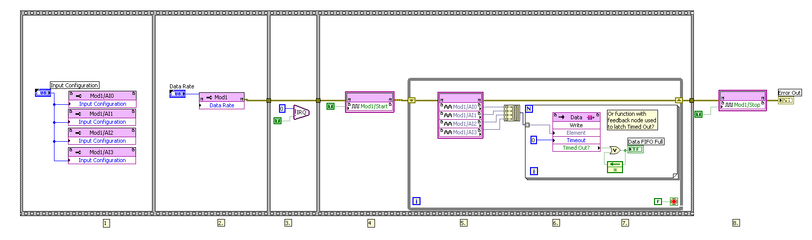
DMA FIFO of FPGA to host RT is full
I transfer data via DMA FIFO of FPGA to host RT.
DMA FIFO is full, I have tried everything I know:
-increases the size of the FIFO DMA up sideways FPGA
-set the depth of the FIFO DMA to 100000000
-increases the amount of DMA FIFO reading in each iteration of the loop
-use a timed with a frequency of 1 MHz, instead of a normal life all loop
Please find attached my project folder, FPGA code and code RT.
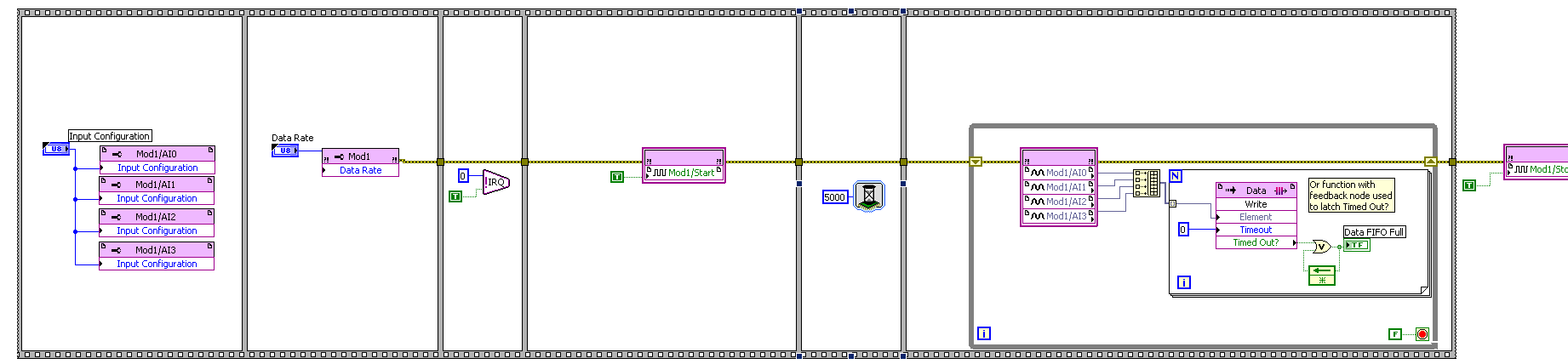
I solved my problem.
Below you will find my FPGA code before solving the problem and after resolution of the problem.
Solution: I just added a function of 5000 milliseconds (5 seconds) to wait before getting the analog input nodes samples (AI).
Before:
After:
Maybe you are looking for
-
Hello I suddenly stopped getting emails today. I have tried everything what you recommend, but nothing seems to work. Please help me! Thank you in advance!
-
Because I have difficulty working with the mouse (like many people), would be nice if I can use the keyboard as far as possible when applications on the computer. I often use Alt Tab, Ctrl-Tab, PgUp/Dwn - < item of menu or button-to-do-something thin
-
I would ask advice if this online store retailer are legitimate. http://www.mskeystore.com/ They sell keys product at a price very very very low. It seems no so much information on this Web site, and also when you open the Web site, they also use the
-
ATV4 shows more the content of the Description tab?
I do not understand why the AppleTV was to change the display of metadata of film of the 'Description' in the 'Comment' [iTunes 12.3.x details tab] field in the 4th gen AppleTV. Swear next to the words I uttered when I realized that all my work to e
-
Creating a loop in which the results are listing to specific columns
Hello I am creating a loop for my data of three columns after being calculated will be converted into three columns again, and then run through text files separated 10 data to add to the new file so that when the loop is complete I have 3 columns wit