Frequency response of a filter
I have the coefficients of the filter from the filter that I need in my program. I need to find the frequency response of the filter. Is there any function in LabVIEW that helps me do that?
I guess I need a function that is similar to the freqz function in matlab for this.
Thank you guys! I discovered what I wanted. But thanks to guide me.
I'll post the answer so that others can use it
First of all, I discovered the transfer (from the filter coefficients) of the filter function using the:
Digital Filter Design toolkit-online Utilities => tf (DFD build transfer Function.vi filter)
The output filter obtained this was wired as a the input filter for:
Digital Filter Design toolkit-online filter analysis-online Freq resp (DFD Plot Freq Response.vi)
I had the required frequency response  .
.
@Sd.Kfz.10 I could not use the filter filter RII where the coefficients are given as input (in the toolkit signal processing) and FIR because I wanted the only filter response. These FIR and IIR filters requires the table of input signal.
I used for the linear predictive coding for speech recognition. I modeled the vocal tract as a model (a filter all-pole) Autoregressive using a the AR modelling.vi in the ADSP Toolbox. I wanted to see the frequency response of the filter modeled but I only had the filter coefficients.
Tags: NI Software
Similar Questions
-
frequency response plot DFD rad / s
Hello
I'm trying to get the filter frequency response using the frequency plot vi DFD response. Is it possible that I can get the mangnitude and phase response of the plots of the frequency in radians per second? Now it gives me focus of frequency in Hz.
Suni-
The output of the frequency plot DFD response is an array of clusters of wave graphic form. You will need to index the table out each graph (there is one in your example) and then bring out the start frequency and out of the frequency of the cluster so that you can convert to radians and insert and rear. The attached picture shows what I mean...
-GN
-
How to convert signals from the time domain to frequency response
FFT. There are several functions, you can use including an express VI outside the basic FFT. Look at the features of spectral analysis.
-
microphone frequency response function
Hi all
I am doing a test with 3 types of sensors to study the properties of the surface of a material.
The first is the sensor in the modal hammer.
The second sensor is a geophone, while the last is a sensor of air coupled in the form of a microphone.
Apart from the microphone that is directly connected to the laptop by USB, the instrumented hammer and the geophone is connected to the NI 9233, which is connected to the NI USB-9162 that eventually connects to the laptop.
Does not support this material analog trigger so software triggering is used.
I use an example of http://www.ni.com/example/28438/en/ vi
I installed successfully the LabVIEW VI to read the raw data from all the sensors and to obtain the frequency response of the geophone due to the momentum created by the hammer signal.
I tried to get the frequency response of the microphone due to the modal hammer However no results appear in the graph for the frequency response of the microphone.
My question is, what's going on and how can I fix this so that I can get the frequency response of the microphone?
I enclose my vi for your review.
I can't fix your VI because I don't have DAQmx or SVFA Toolbox. What I joined is a simulation that shows some of the concepts.
The left side simulates the acquisition of two channels (hammer and geophone) via the DAQ hardware and a sound channel (microphone). Don't worry too much about the details. I just threw together quickly. The hammer is a square pulse, the geophone signal is a cycle of a sine wave with the noise and the microphone signal is a cycle of a triangular wave more noise. Each pulse is delayed at the beginning of the acquisition by different amounts to represent delays of transmission of the audio and vibration. The values are arbitrary and do not simulate any what physics.
I used the sampling frequency, block size and controls the duration of your VI, so the number of samples and the sampling frequency should be the default values for your VI. The three graphs show left the three generated signals. Note that the Microphone graph x autoscaling off axis. Also, the data are all in waveforms or arrays. I avoid using the Type of dynamic data produced by screw Express because it effectively masks the data structure.
The right side shows a way to make the trip. I used the basic Detection.vi of the control palette trigger level of waveform and get the Subset.vi of waveform in the waveform palette. Note that there is separate shutter screw for acquisition of data channels and the sound channel. Because they are not started at the same time and they do not have the same dt (= 1/sample rate), the waveforms are not cumulative to use a single trigger. The geophone signal is synchronized with the hammer for a trigger signal the hammer can be used to get the two subsets.
Note that with the default times the pulse of the microphone occurs 30 ms after the geophone impulse but in subsets, it happens about 4 ms before the geophone. This is due to the independent intervention.
Since you do not have a common signal or a trigger for both devices (acquisition of data and sounds), you may not know exactly what the relationship of synchronization between them. On each run, the differences between start times will vary. So, you will need to make some kind of calibration to determine the offset. I think some sort of periodic stimulus that will produce several impulses for the geophone and the microphone. The first pulses aura of indeterminate delays but subsequent impulses should be reproducible delays. The relative spacing and directions during the calibration tests must be identical to the position of hammer for the real experience.
Lynn
-
To listen to the song without any eq you set normal Fuze, classic or custom (without making any of the sliders in the centered position). Looking for a flat frequency response.
Thank you
barondla
barondla wrote:
To listen to the song without any eq you set normal Fuze, classic or custom (without making any of the sliders in the centered position). Looking for a flat frequency response.
Thank you
barondla
The answer is 'normal '.

-
I probably wouldn't ask this question because I charge people for my amateur obviously recording capabilities but it's one I've ever had explained to me and I need to know the answer to one...
I would like to settle the matter in this way:
When you get in the car and pop in a cd of product professionly, most of the people get the control treble for 6-10 (on a scale of 10) and bass (4-10) upwards according to the factory speakers and the type of material and whether or not they care what their music sounds like. When you get home and you listen much finer stereo home always to listen to professionally produced album, always reach you for these high and low buttons and crank them several notches or if you have a graphic equalizer twist you on a smiling face .
There is so much importance in the world of recording to get out of your room with shock absorbers flat frequency response and bass intercepts and spread around the reflections with deflectors, etc etc... etc., we spend thousands of dollars on such things and some measurement software to make sure that it is flat. Then we use this flat response to produce music that sounds good and waiting for the translation of these cd players and home stereo systems.
(I will additonally Preface my question by saying that I had no problems to make my music to translate my home studio to any other system of reading, but I'm a little confused as to what is happening.)
Now finally my question (s), when we reach for these buttons high and low on our car and home reading systems, are we really just try to compensate for the lack of bass and top of the range in these systems so that we can get a flat frequency response and too make the music sound good on any system? or
Do we as listeners prefer the face smiley in music frequency response and are we take a cd that has a flat frequency response and make a smiley face out of it to make it sound to our ears? (Please don't give me an answer for material/gender.)
The reason why I ask is because I have to put a graphic equalizer on my monitors 2031A truth to make professional stuff sound good thanks to them and then I Mix round my music for the same material/any sound of course. (I'm not really interested in any monitor bashers or I would already put this on to Gearslutz.)
Even once be reformulated... The masses think that music sounds good when you have a flat frequency response or the smiling face and if the these States among young people, how are supposed to realize that when the facility from our home studio produces a flat frequency response, do give us our EQS instructors like me?
Additonaly, I understand that when talking about frequency response flat in the rooms, that we are not talking about launch thanks to a system sine waves and the going of their frequencies, measure so them we can detect everything on the focus/deficiencies in the room then maybe this question is a little more to the tuning monitor.
If you are looking for Fletcher and Munson in Google, you could start to do a little the beginning of any idea why this is not quite as simple as it seems... and I'm not sure I can give you a complete answer, although I peut give you a few things connected but somewhat randomly, to meditate wearing my acoustician Hat:
The fundamental problem is that, when things are quieter (and less distorted, by the way) our ears get more sensitive to frequencies medium, and if we listen to music like that, it always sounds as if the bass and treble are unbalanced. In cars, it is slightly different though; the frequency response of everything that is there generally tends to be anything but flat - and often too emphasizes the middle range anyway. Treble tends to be absorbed very easily in padded cars, and because most car speakers got nothing as acceptable to the tweeters in order in General, it is not surprising that people want to increase the treble. As for the bass - well I am still lower that personally, but I know what you mean in principle!
If by a "commercial" CD, you mean the one where the voice is important, so yes I can easily imagine why you could as naturally want to increase the response to the extreme - that makes sense, if you think about it. The mid-range voice is prominent and probably compressed, so its average level is stronger support - helps it stand out. But also it distorts the overall time response - support can be balanced so it's not serious in itself, but which does not always if you have the wrong applied voice settings, or at the very least, applied said. And some voices are much worse; for example Sealion dying (AKA Celine Dion) makes the most appalling racket in the middle range, and you should certainly less of it!
So, really, I would say that it is not a question of bass/treble, but a mid-range one. If you look at commercial CD in general, you tend to find that the energy distribution is pretty even on the entire audio band, which means it comes off at 6 dB/octave, if you look in hearing (it is something energy/Hz), but in reality most of the CD these days are here mixed a little brighter than that - more like a - 3 dB/octave descendant of about 1 kHz , and it is partly to make up for a lot of things - some of which are cars... You have to watch out for the problem of good distortion - most people don't realize, but you are able to tolerate rather high undistorted sound anything with levels of serious distortion in it, and if this distortion is in the middle range, then you will like it more quiet even when. Then under-run decent, over-rated sound systems always sound more clean and strong but you should beware - they can damage your ears just as much, if not more.
Car interiors they increase the chances of the mid-range boost that occur? I think it's a pretty safe bet they do, in General, simply due to the size and the acute problem, I've already mentioned. And if you try to compensate for too much mid range, then the rest follows. More home replay systems these days seem to be heavy mid-range for me as well - I heard something cheap recently which was something as a flat - response and they really agrees that they are in both chambers.
If you want to listen to material as it really should be, then you need to experience it live first, and then I would say do a direct comparison with what you hear in your monitors. I'm lucky - I can do fairly regularly with a variety of materials. I tend to leave things like dish, as they are saved? Well, it depends on what it is. If it is somehow classical, then sometimes I watch carefully the low balance, but generally, I leave the rest alone. The rest of our days I just get its good - and this can mean all sorts of settings, depending on all sorts of things. More and more, I came to the conclusion that medium too is not necessarily a good thing – but it's mainly because of the general lack of good material around these days.
Regarding the monitors and flatness - well it is not really a problem for most people, compared with obtaining their correct listening environment. If you have a pair of cheap monitors in a good room, chances are the results will sound better than a cheap pair in a room uncorrected - despite what all fans of monitor on gearslutz might say. Nowadays, even the least expensive may seem quite respectable. But the flatness is not really a problem with the monitors - a decent impulse response and low distortion are much more important. Chances are that if a manufacturer got that right, the monitor will be properly 'revelation' anyway - which is what a monitor is supposed to do.
The only thing you do not do however, is QE the stream of your monitors - that went out of fashion, as soon as he came in--fortunately. You can set the room so that it is the most truthful. If you EQ the battery monitor, it will inevitably be only its good in one place in the room, and it's no use to man nor beast. Things only decent that can do real room correction systems is to equalize the immediate response of time to account for what is actually between you and monitors which if done properly can improve an image without end stereo.
If the answers? Well not really. But at least I explained a bit (but not all) of the questions.
-
. VI filtering IIR and response: response of Butterworth filter size depends on sampling rate - why?
Hi people,
I'm not an expert in the design of the filter, only a person in applying them, so please can someone help me with an explanation?
I need to filter signals very infrequent using a buttherwoth filter 2. or 3. order of the bandpass 0.1 to 10 Hz.
Very relevant amplitudes are BELOW 1 Hz, often less than 0.5 Hz, but there is as well the amplitudes beyond 5 Hz to observe.
It's fixed and prescribed for the application.
However, the sampling rate of the measuring system is not prescribed. It may be between say between 30 and 2000 Hz. Depends on the question of whether the same set of data is used for analysis of the higher up to 1000 Hz frequencies on the same measure or this is not done by the user and he chooses a lower sampling rate to reduce the size of files, especially when measuring for longer periods of several weeks.
To compare the response amplitude of 2nd and 3rd order filter, I used the example of IIR filtering .vi and response:
I was very surprised when I found that the response of greatness is considerably influenced by the SAMPLING RATE I say the signal generator in this example vi.
Can you please tell me why - and especially why the filter of order 3 will be worse for the parts of low frequency below 1 Hz signal. Told me of people experienced with filters that the 3rd oder will less distort the amplitudes which does nothing for my the frequencies below 1 Hz.
In the attached png you see 4 screenshots for 2 or 3 command and sampling rate of 300 or 1000 Hz to show you the answers of variable magnitude without opening labview.
THANK YOU very much for your ANSWERS!
Chris
Hello Cameron and thanks for my lenses of compensation.
I can now proudly present the solution of my problem.
It seems to be purely a problem of the visualistion information filters through the cluster of the scale.
After looking in the front panel of the IIR, I suddenly noticed that the "df" of the pole size is changing with the Fs of the input signal.
For a Fs to 30 Hz, the "df" is 0.03 Hz so you see the curve of the filter with more points, see png.
For a Fs 300 Hz "df" is 0.3 Hz, so the curve is larger with only 3 points between 0 and 1 Hz.
For a 1 kHz Fs the df is 0,976 Hz, so there is no point in the graph between 0 and 1 Hz.
It's strange that for constant Fs, df of this cluster NOT reduced with the increase in the number of samples, as it does in an FFT.
However, I hope now the filter used now for the curves obtained with the proposed Lynn way and the response of greatness from the filter information fit together.
Thank you for your support.
Merry Christmas and a happy new year to all.
Chris
-
Pavilion TS 11-e100sr: frequency response of TS - 11 1 / 8 "Jack
Hello
I tried to play on his return from my new Pavilion TS-11-e100sr using jack 1/8 ". The sound was audible equalized for portable speakers or headphones may and was terrible when he read through external sound system. I measured the voltage output on jack 1/8 ", generated sinusoidal waveforms of constant reading. The result is shown in the attached photo. As you can see, there is a little push huge 6dB 100 Hz and - 3dB cut in the middle of range around 300 to 400 Hz. At high frequencies, there are also 3 progressive dB push up to 16 kHz. I tried to find where I can turn the EQ off but I couldn't. Can you please ask me what should I do to get uniform frequency to the output response?I found a solution. I replaced both drivers Realtek with Microsoft, and gives a flat response near the plug of AC 97.
-
Good application of a filter of 50 Hz
Hello
I need to apply a filter of 50 Hz to an acquisition of signals DAQ (noise for testing).
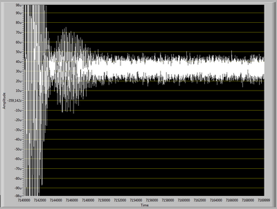
When I apply the filter, the resulting signal has enormous oscillations in the first part of the signal acquired (as see you in "Filter output.png"), after these oscillations, the signal becomes filtered as it should.
I tried to change the sampling frequency, the frequency of signal acquisition and all other settings, but I can't get rid of these oscillations.
What Miss me?
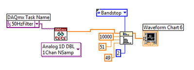
In "Diagram.png", you see the pattern of the filter.
The signal is acquired at 10 k rates and includes 30 k points.
I have some experience with Labview, but I've never used its filters.
Thanks for the help
Your image resolution is a bit low to be sure, but it seems that you have a significant lag in the data. A mismatch can lead the transient response of the filter. With a filter bandwidth, which can produce an oscillating reaction.
With your entry of noise you get very little energy in the band stop filter so it can be difficult to see the effect. When I simulate your signal with offset of the hard shoulder is almost impossible to detect. The noise in each tray is approximately 60 dB below the offset and the stopband attenuation is about the same. Without the offset the stopband is detectable (visually on a graph) about a quarter of the time. With 300000 samples, it is almost always visible with or without the offset. See the image below.
This is the spectrum of random noise with shift amplitude of 5 times and 300000 samples.
Usually interpreted restrictively the frequency response of a filter, more transient response.
Lynn
-
Filter of time domain frequency domain filter
Hello
I am applying the weighting filtering of an audio signal.
I'm to draw the response of the filter in the frequency domain.
How can I turn this into a time domain filter and use it with a real audio signal?
In theory, it's pretty simple. You take the s-domain transfer function and apply the bilinear transform. After a few edits, you can extract the coefficients 'food for animals-descendant' as well as the coefficients "feed-forward". These coefficients can serve as input of the filter of Labview functions. As I said, the theory is simple, but I think it will be a tough job to do this. Weighting is used in the measurements of the sound level, to mimic the curve of the human ear. If you plan to use spectral analysis in your application, you can skip the filter and apply your formula for your spectrum frequency bins. In this way, you can save a lot of work, because you stay all the time in the frequency domain.
-
Questions about the frequency step response
Hello
I use the Signal Express 3.0. I'm not clear on the transfer functions in step of frequency response with different modes of calculation of the average. What I got from the help file is this H (f) = Sab (f) /Saa (f) which is cross the frequencies on the spectrum auto where is the pulse and b the signal response signal. When the mean quadratic value is used, I wonder if the transfer function becomes greatness of cross spectrum divided by the magnitude of the spectrum of the car. When an average of vector is, everthing is used in complex numbers. He averaged temporal signals, frequency domain signals, or the results of transfer functions?
Thank you very much.
The algorithm to calculate the spectrum is the same in both modes. However, the method of calculation of the average can have a huge impact on the outcome. Mean quadratic value is performed on the spectrum itself, after the calculation. Vector averaging is done on the input signals before the calculation. With an average of vector signals must be consistent (have the same phase) or the result will be bad due to the signal being on average by far.
-
Questions about an average of response spectrum and frequency of feeding mode.
Hello
I have a few questions about an average of mode. When I generate a sinusoidal signal from one output to two input channels channel to see if my DAQ card works well and vector averaged in the power spectrum for DFT, the amplitudes was different from the previous one of the amplitude, which was supposed to be 1 v peak. They range from 0.5 v to 0.6 v peak. When the calculation of the average model is RMS, the amplitudes were close to 1. I wonder what are the fomulas of RMS and average vector. Does that mean that I could not accurate if I use an average of vector? In a time of frequency response, why I coherences of difference and the amplitudes using the vector and the mean quadratic value?
Thank you
Ningyu
rico1985,
The differences in modes of generation are as they sound: 1 sample output only a sample writing, N samples will be released however many samples configure you for each entry, and the continuous samples released samples continuously until a specified user action happens (you press the stop button or a logic that you created gets fulfulled). The range of Signal output allows you to set a ceiling high and low level of your output signal and it only affects the quality keeping in this beach. Timing to set a deadline for the time between the acquisition of the sample. If a new sample becomes unavailable before the timeout setting, you will get an error. This is useful for looking at a network, because if the network goes down and you stop getting data from a machine and then you would like to know about it. I point you to those videos that are short tutorials on how to make the most of these actions in SignalExpress.The SignalExpress 3.0 Help file is also your first point of contact for all your questions on getting started. These two resources should get you up and running in SignalExpress in no time. (either by the way all your questions answered using these resources) Bravo!
-
buterworth sampling frequency filter
Dear friends, hope it's a good day
I was wondering what is the best sampling frequency if the buterworth filter configured to. I know that some of you suggest trying different values from 1000, but I ask just for the guys in your experience.
Thank you very much.
Bill David,
It must be set to the sample rate of the data that you are breast-feeding to the filter. If you buy data from an analog to digital converter, use the sampling frequency of the converter.
I think that the default is to assume that each element of the input array is acquired to 1 second after the previous element.
Lynn
-
Response frequency (simplified answer)
Hi guys, I would like to use this method (this appears as an example vi) to determine the frequency response of my system with my input signal (no answer: square wave) I'll first need to "pull" the impulse response. Can someone explain what 'pull' means on this occasion. In the example, it uses a call to the library, but I need more details. Thank you, ds1
If you try to get a frequency response of a system, I highly recommend looking into the following Toolbox:
http://sine.NI.com/NIPs/CDs/view/p/lang/en/NID/13853
Here is the Manual:
http://zone.NI.com/reference/en-XX/help/372458A-01/
Here are some tutorials:
http://zone.NI.com/DevZone/CDA/tut/p/ID/4170
http://zone.NI.com/DevZone/CDA/tut/p/ID/5536
http://zone.NI.com/DevZone/CDA/EPD/p/ID/5162
Hope this helps
-
How to find the frequency bands of the TPL for Wavelet db04?
The President complied,
I'm doing project on the simulation of the EEG signal, processing and analysis. I want to find the frequency of the signal band after having extracted the detail and the approximate coefficient. Here I used a Wavelet analysis (db04). I'll be gratfull for you if you can help me in this matter.
Thanking you.
Hello
You can use WA Wavelet Filter.vi to obtain the coefficients of the filter used in Wavelet transformation, then you might anlayze the frequency responses.
Thank you!
ZJ Gu


Maybe you are looking for
-
Support for Windows 10 for Satellite C885D
I currently own a toshiba satellite laptop computer model c855d-16j and I tried to upgrade to Windows 10, initially, he begins to update and reach 86% where he begins to reset, the problem is it doesn't do anything from there and I'm stuck on reboot
-
I have a tree with two columns. How to add Label1/value1 to row0, col0; Label2/value2 to row0, col1; Label3/value3 ro row1, col0; Label4/value4 to row1, col1 and so on. By looking at the examples of the InsertTreeItem() tree, I am only able to add la
-
Error code RunDLL on computer starts.
I have problems trying to figure out a code of RunDLL error (C:\User\A***\AppData\Local\eyowuroviqohuwy.dll) I get when I start my computer. I ran my Microsoft Security essential program and yet it continues to rise. I would really like to know what
-
Programs do not show in Add/Remove programs
Earlier, I noticed that most of my programs has disappeared on my laptop ' Add/Remove Programs". I keep in great shape and never have a problem with it. It's my father for pets only, only a fraction of my programs are listed and I can't uninstall s
-
Hello I'm new with the blackberry development. I want to request a dialer. In this I need help to know how to start with his conception of the Dialer. (buttons and TextBox etc..) Can someone help me with this? Thanks in advance...