frequency RPM
I need a measure of RPM to a BLDC. I have Hall input signals. I use a cRIO and I program on the FPGA.
So I measure the frequency of a signal to entry hall, using a single loop timed on the FPGA.
In another loop I calculate the number of turns of the frequency. This according to the number of poles.
When the engine is running, I see change the number of ticks, but calculated SPEED does not change, it is fixed at 5299,41 RPM.
I hope someone can help me.
What is the settings for your type of Point data sets? I think you're just hitting the limits of fixed point settings. You may need to convert it into a floating point and the agenda of do all the calculations.
Tags: NI Software
Similar Questions
-
Error on wait the next sample clock
Hello
I need measure the speed using an encoder for a control application. I installed a sample external clock on CNTR0 (in another vi) and I wired CTR0_OUT to CTR1_GATE. I start the vi, then the measure of the clock vi speed sample and Labview displays the following error. I don't know what is happening, my measure is established for the sample clock and timing type single-point sample clocked by material and the error says that I do not have this? What's funny, is that the same app works if I am using the DAQ Assistant.
Thank you
David
Hey David,
I believe that the document I linked can be a problem, and I'll go ahead and make the necessary changes to be made to this document on my side.
The next issue I can see uses HWTSP on a windows machine. HWTSP is usually reserved for computers running real-time operating systems. These operating systems can ensure deterministic operations. On windows XP, windows may decide to treat another thread / process that can cause you to miss a sample (if you miss a sample that the default behavior is to throw an error).
With HWTSP, you will be difficult to get one without a real-time system faster sampling rate. Stamped acquisition will also have a large amount of latency for a control application.
Looking at your code, I recommend trying a task of sampling frequency CI On Demand. Currently, your code is the edges and conversion of frequency/RPM. In addition, because of the lag phase with your sample clock, your current configuration has an error of ±1 count. This translates to error ±1KHz (on behalf of 9 to 1 ms it would be 9 kHz, 10 would be 10 kHz, etc.). Based on mathematics in your example, you introduce ±120 rpm of error. By a frequency on the task on demand, you can ensure that whenever you call the DAQmx Read, you get the last frequency within a tick of time base error ±1. Not only it gives a better accuracy, but as long as you keep the rate of fast loop, you will ensure you get the last frequency to the fastest rate possible.
Ensure that your loop rate remains fast is to remove the loop of your acquisition processing and placing him in a parallel while loop. This is possible through the use of reporters. Local loop in Windows rates are usually in milliseconds. To get faster line rates, you might want to consider a real time operating system.
Please let me know what you think of this, and if you have any other questions, I can go into this more in detail.
-
VI to convert input signals NI 9402 in a RPM value, based on the frequency of the pulses
Hello
I'm looking for a VI convert an input signal NI 9402 in a RPM value, based on the frequency of the pulses. Is there such a thing that exists in the library of national instruments?
I run LAbview 2014 integrated control and monitoring on on a cRIO 9802 high performance integrated system with NEITHER 9402, 4 channels, 50 LV, LV TTL Module input/output digital, ultra high speed digital i/o for the cRIO module.
Any help would be greatly appreciated.
The easiest way is to use the FPGA to get the time between the edges of your pulse increase (shift registers to maintain the current situation and the time will be necessary). This will give you the period. If it's a single pulse per turn, then the number of laps is just 60/T, where T is the time in seconds.
-
How to measure the frequency of NOR-DAQmx RPM tasks
Hello
I'm trying to measure the frequency using the NI DAQmx task and then convert it to a RPM if possible.
I have the following material available to me.
I have a block SCXI-1327 terminal, as well as a 6289 PXI multifunction data acquisition Module SCXI 1126.
I wired in a mag ai7 sensor on my 1126 and then of the passage of an object metal I get a range of 6-8, so I am able to read the mag sensor.
What I'm trying to do is somehow convert this analog measurement a RPM using the NI DAQmx task only.
Any help would be appreciated.
Hi, smooth,
Yes, you would select linear, then put in the result of this calculation of the slope.
The Manual recommends a minimum frequency of at least 15 Hz for setting low range. This card is not really designed to measure the frequency for a single pulse over a long period of time.
The number of LAPS down (assuming one pulse per turn) that we recommend that you measure with the 1126 is so 900 RPM. If you need measure low revs, and you cannot increase the number of impulses per turn, you could consider either read the signal as an analog waveform, or if it's a digital pulse, using a counter to basic task. In this way, you can use any method you want to handle the situation where there is only a single pulse in a long time.
-
cDAQ-9178 & NI 9401 - ASM: incremental Rotary encoder works is not beyond a certain frequency
I use a chassis with a NI 9401 DIO module 9178 cDAQ. I'm trying to convert the output of a rotary incremental encoder ASM (in radians) to rpm.
Sensing head (PMIS4-20-50-240kHz-TTL24V-Z0-2M-S)
Snap ring (PMIR7N-20-50-M-20)
The encoder outputs 2500 pulses per rev (output 5V TTL). The maximum speed which will see the encoder is 2800 rpm, which is equivalent to 2800 RPM * 2500ppr/60 = 116,667.67 Hz in terms of frequency.
Since the NI 9401 of the operations specifications:
Maximum of the input signal switching frequency by the number of input channels, by channel
8 input channels... 9 MHz
4 input channels... 16 MHz
2 input channels... 30 MHzI use only 1 channel, so I'm assuming that the 9401 should be more than capable of handling the 116kHz which the ASM encoder is spit.
Everything works fine until about 2100 RPM (~ 87, 500 Hz) but then I begin to see a drop in rpm, followed by a flattened behavior, then a slight increase. But never more than 2100 RPM. Our test unit is inspected for other reasons at the moment so I can't produce a plot of the behavior (I can reupload later). I think this must be a matter of aliasing with the meter or something of the sort. I have a digital filter set in place with a minimum of 4.0E pulse width - 6. It is two times smaller than the width of minimum pulse at a frequency of 116kHz (0.0000085714). I don't think this should have an impact on the calculation.
Any suggestions? This value of RPM is essential to our application.
Thanks in advance,
-MB
brown_ktr wrote:
I have a digital filter set in place with a minimum of 4.0E pulse width - 6. It is two times smaller than the width of minimum pulse at a frequency of 116kHz (0.0000085714). I don't think this should have an impact on the calculation.
A 116 kHz frequency, the period is ~8.57 us, but the pulse width half duty cycle of 50%. Ascent/descent time factor, and it is quite possible that 4 US is too long for your encoder signal.
The shape of this graph supports this theory, if we consider that there is variation in the exact pulse of each encoder pulse width. The shortest pulse is ignored when the filter starts to kick in, and the speed of ROTATION increases pulses longer and longer are ignored then as well.
Try to decrease the minimum pulse of digital filter (US 2 or even 1 US) width and see how it goes.
Best regards
-
Measure the movement against the frequency
My test is measurement and tracing motion valve engine RPM. I need the valve position sample (analog signal) all of the pulses from a rotary encoder and also enjoy RPM. Then later I have to extract unique plots, each revolution of the position data. Each parcel must be referenced against the RPM about during which it was sampled. This will take place at the 66kHz about 8 seconds while it will generate a long file.
I suggest you begin the Z (1 per rev) pulse signal sampling and 1 post analog SOUL each dry vegetable (720 / rev). Store this table. At the same time I want to run a task to capture the frequency once every revolution (pulse Z) by measuring a pulse. Store these vals to a separate table.
After measurement is done I can record the position great soul array in a file of measures and record the frequency data in a separate, much smaller file (let's call it an index file).
In this way, for the analysis, I can load the index table and count the length of it in order to determine the length (in points of data) of the large table soul. This could allow me questioning the guard index for a selected rpm and select the correct positional score 720 for conspiracy against angle encoder (tracing movement is against increments of 1/2 deg as x.)
This plan has any merit? I'm new to this type of measure, and if someone knows of similar procedures I hope you hear and taken into account. Is there maybe a better way?
This seems reasonable. Look at the threshold of the 1 d Array function. You can use it to search the Board index to a certain speed. Round off the result to the nearest smaller integer. The index in the positional table will be 720 * this integer (- 1). If your speed can vary from top to bottom, you may use the start index or reverse the table to find the location you want.
Lynn
-
NEITHER USB-6343: erratic low frequency 1 counter measures
Dear members,
I'm looking for help with a measure of low frequency counter. I tried to make it work for a week or two, but I keep getting erratic measures. It will read the rpm properly for a second or two and then it will give a ridiculous value on the order of 10,000 times the correct value. I can not get a constant value.
I use a DAQ series X NI USB-6343 multifunction with Geartooth Honeywell GTN1A111 sensor. I enclose a sketch of the wiring configuration. I think that it is correct. Sensor output to the door of the meter.
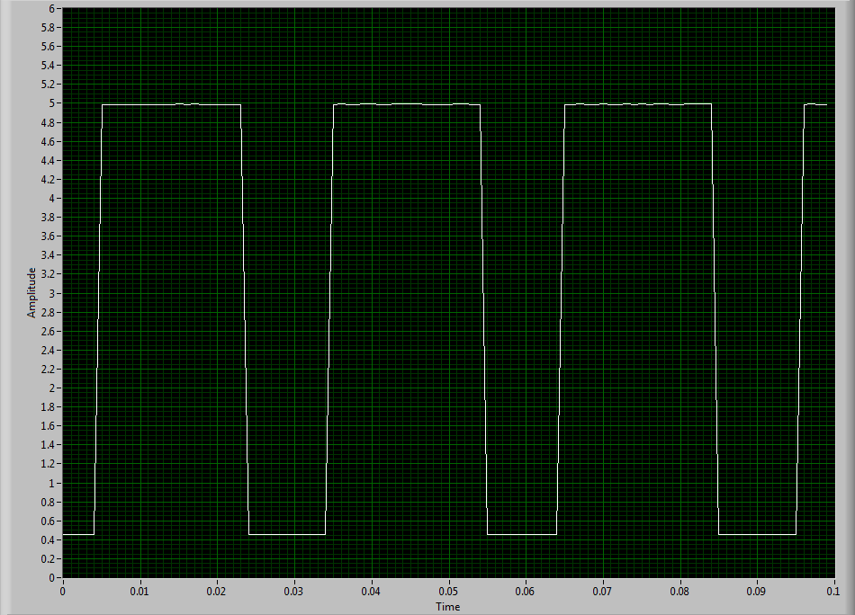
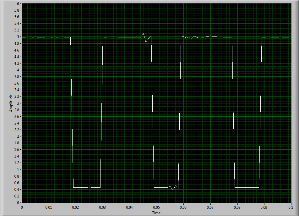
To try to solve this problem, I hooked the sensor to an analog input channel to make sure that I was getting a TTL signal by sensor. I noticed every once in a while I'd see a glitch of little noise in the signal and I guess that's what is causing my problem with the meter. I inserted two waveforms of the sensor signal (one with the clean signal) and the other with the glitch of noise. My understanding of a TTL signal meter channel will examine LO voltage when it is below 0.8V and HI when it is larger than 3.8V. So I really do not understand why these little glitches could be the cause of the problem because they are well below and above 0.8V and 3.8V, respectively. I think that the noise comes from a frequency converter used to drive the engine. I tried the system as much as possible of the Earth.
I guess I'm looking for another approach. I could potentially use a digital filter to help with noise? The glitch is in fact the problem or I forgot something. The VI in question is attached.
Thanks in advance,
Mike
Have you tried to set up a digital filter yet? Obviously the seeds are collected as an additional transition (the method of low frequency counter 1 measure the period and then reverse, so a short glitch would record as a very high frequency).
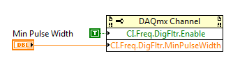
You can enable the digital filter with the following property node:
Min pulse width is guaranteed pulse past the filter, so it should be low enough for the real signal is guaranteed to pass through (but high enough so that the glitch is always rejected).
Best regards
-
Combining the scalar output with the acquisition of data time vs RPM
I have no idea why my 9402 NOR does not work as it should, but I don't know he counts the pulses, and at that time I need data for my forthcoming report.
I came to a .vi that contains a very basic way of relating counties in time, however, I need to save the data to an excel sheet for I can analyze it. I have a motor which is connected to an assembly. My encoder measures the rotation of the shaft (no measure of direction availible) which is directly activated by the engine. As load us the assembly, I want to see what the speed of the motor through the encoder. So let's set the engine speed (anywhere from 1 to 100 rpm) and then load the assembly and see if the engine cannot maintain speed. Seems simple but my module is having a difficult time getting one any frequency of the encoder.
Anyway, the .vi I use counts the pulses and divide them by 100 ms once every 100ms. This generates a scalar value that I want to record with regard to the overall time, prefferably every 10th of a second (100ms). I know that I combine the values in a table (2 columns, an indefinite quantity of lines). How can I combine two elements ([time, RPM]) in a table every 100ms and having the table keep expansion of the lines until I hit stop?
Hello Evan
There you go!
Mart
-
Synchronization of two inputs frequency meter with several analog inputs
Hi all
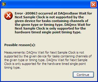
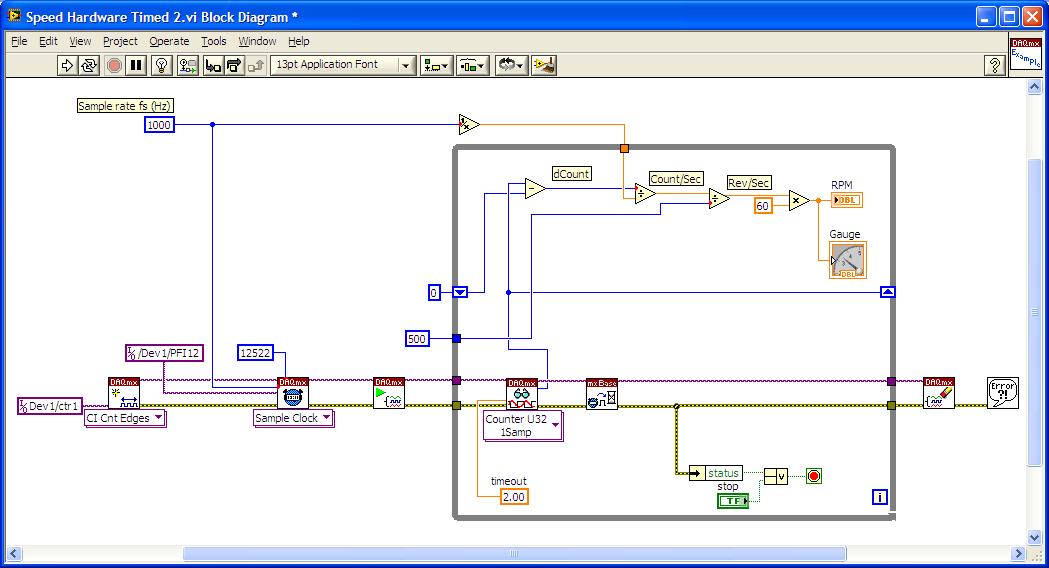
I'm relatively new to LabVIEW and I'm trying to collect data from multiple sources with calendar sync on the acquisition, but I can't understand. My problem is that I have two inputs frequency meter, an optical tachometer reading one pulse per revolution and a max flow meter machines with a 12000 k coefficient. I can't find a way to synchronize the calendar with my multiple analog inputs. I tried to first get the speedometer to synchronize with the analog inputs following the example linked here. (https://decibel.ni.com/content/docs/DOC-10785) So far every time I run it I get an error on the DAQmx read timeout or an error "several sample clock pulses have been detected" (see image). It seems if I slow the way to down to say 10 hz and make sampling rate ensure that the tachometer signal is more than 800-1000 rpm (13-17 Hz) before starting the VI then the program will run without error until the ROTATION speed is below this threshold, then the "sample Multiple clock pulses" error occurs. The code is attached below.
Does anyone know of a better way to synchronize the entries of frequency of the counter with analog inputs? I would like to have a VI that can display 0 RPM (and possibly 0 flow as well, but I think I need to understand the timing of a meter before I have add another, because it seems that I can't have two counters to the same task). Any help on this would be greatly appreciated.
LabVIEW version 13.0
Chassis cDAQ-9178 with NI 9401 for both counter inputs and NI 9205 for the analog inputs.
Thank you!
Richard
I know the error requires to restart the task at least (this particular error puts the material in a State that cannot be recovered from during execution of the task - I've been down this road before) but I'm surprised that you would have to delete and re-create the task altogether. And then I had to do this to workaround other questions in the past. It is awkward and should be considered a bug, if this is indeed the behavior.
Honestly, regardless of this bug, the way the material dealing with the situation of several sample clock edges makes measures of sampling frequency clocked essentially unusable for purposes of synchronization (in my opinion anyway) If you encounter a more slow than your sample clock rate. You are supposed to be "synchronization" of the measure, but it really no longer applies if you have to restart the task over and over again (if you must delete it or not).
Workarounds can get kind of creation (which isn't really a good thing). For example, you can configure a measure of implicit frequency to keep a buffer of frequencies and use a leader board task (source is the frequency signal, sample clock is the sample clock HAVE) to establish a correlation between the index of your buffer of frequency for singing HAVE sample clock.
Best regards
-
Reading and samples the sampling frequency using a fast external clock
Hello
I use an NI USB-6212 box to launch a search engine for combustion. I have a pressure sensor in the head and a wheel on the crankshaft. I use the beats A Quad channel of the rotary encoder as a sample external to the pressure with the sample clock. The idea is that I want almost the same number of points in each trace of pressure so that it is easy to average together. I seem to be able to do this at low speed, but I'm having issues at high speed.
Can someone tell me what I should have my sampling rate and samples to read together and how it effects my sampling when using an external clock? Samples per channel will affect the size of buffer and that matters? When I was high (10-100 kHz and about 1/10 * rate for samples to read) it barely read but as I put the lowest and lowest he read faster. Play with the settings a bit seem to affect how well it samples at different speeds. The engine is running at 3600 rpm and my encoder puts out 2500 pulses per turn on one channel, I'm looking at a frequency of 150 kHz effective sampling. However I didn't sample program with the engine operating at full throttle. I hung on the output of the encoder up to a scope and reads very well.
Are there opportunities the filter counter that I see in the manual of 621 x is enabled inadvertently?
Thank you
Xander
Xander18,
I suggest you move your screws initialization outside the while loop, as well as your narrow DAQmx VI. On my side, it looks like a new task is performed for each loop, which takes time. That a try and let me know how it goes.
-
Hello
I use PCI 6025E to control load Bank and to measure the voltage, current and frequency of a generator.
Current and the frequency is not a problem, voltage is toublesome.
As on test bench already there are few PCI cards and large number of sensors, I don't want to add NI 9205 or any other additional maps and the size of the area (other people are also working there).The problem with blood pressure is three two generators spend 400 rpm to 1600 rpm is. some 15 to 55 Hz.
I got two solutions for this:
1, put a step down transformer (230 Vac / 5 Vac) and then measure the voltage. But I have to deal with magnetic saturation with commercially available processor during the test to something like 15 Hz. I don't want to take the pain to built my own transformer.
2, using high precision voltage divider. The problem is that what should be the galvanic insulation? Insulation transformer, but still low frequency problem.
Where could someone suggest me because there is a bit of confusion in my head.
Thank you.
If you have a sinusoidal generator (15 Hz migth be hard for the soundcard
 ) you can do a calibration of your transformer.
(If only the amplitude of the voltage is of interest, use a DMM isolated as a reference and run your generators)
Or you buy an insulation voltage amplifier. (weidmueller, phoenix, wago,...)
-
Measurement of frequency triggered? NEITHER 6259
I'm trying to work out how to implement a measure of frequency (of a pulse train) which will be triggered by another external pulse to a different channel.
I have an encoder that is attached to a rotating shaft, that generates square pulses 5V on two different channels: the first string gives one pulse per revolution of the shaft (my planned trigger pulse), the second string gives a pulse all the 1/2500th of a revolution (IE all 0.144º)
Seeing a pulse of "channel one" (the pulse of a time-by-rev), I want the system to begin to measure the frequency of the pulses on the 'two way '. This isn't the average frequency during the ENTIRE revolution I'm after: what I'm shooting looks more like an angle vs revolution frequency waveform graph, for a ride (IE with 2500 data points).
It does not matter if the processing time means that the system of "lack" an impulse to start on the next revolution, because it can always wait for the next. The most important thing is that the beginning of the frequency measurement is triggered at the right time.
So far, I have used L'Express VI/DAQ Assistant to implement a measure of the frequency of the pulse 0.144º: I'm wiring these impulses to PFI9/CTR0 of Council 6259. I used a continuous acquisition of 2500 measures. The expected frequency range is about 40 to 200 kHz (2500 pulses per rev at between 1000 and 4000 RPM.)
That works very well, and I can establish a curve of angle vs. frequency of revolution, BUT... For now the beginning of the acquisition is completely arbitrary; That is, it starts when I type 'run '. I can't understand the best way to trigger the acquisition of the OTHER channel impulse.
There is no external trigger options in the DAQ assistant page, so I wonder if this is still possible using an express VI - do I have to use lower level stuff?
I am convinced that this should be easy!
Thanks in advance
Theo
Rico, Brad,
Thank you very much for your comments, I'm pleased to say that we have sorted in the end.
The first question concerned the fact that the Board I was using (PXI-6133) is not able to make a measure of frequency of trigger in this way.
It was a big problem because even if the LabView code was right it works always, leading me to doubt the code and become even more confused! However, using the same code on a Board 6259 worked like a charm.
I used the DAQmx blocks to set up a channel to measure frequency and a trigger, set the shutter button using the property with an arm.start node as in your example.
Thanks again for your help!
Theo
-
Is 6200 RPM under normal conditions of Macbook Pro?
Hi all
Greetings for the day...
Normally, I do not play games and it was the first time, I downloaded Dirt 3 on my MacBook Pro model no of retina and noticed that during the game, temp has risen about 75 and the fan speed was so fast it was audible. As I SCM fan control, I just checked my fan speed, he looked at 6200 rpm, is - it normal like playing games or is there any concern that I need to worry?
Thanks for your help... Bravo!
Games often is resources intensive applications and will focus on the CPU/GPU to create heat. What you are experiencing seems to be normal. Fans will accelerate in order to dissipate the heat, so the speed of 6200 RPM is not unusual. temperature of 75 ° c, but on the high side, is well below the limits of functioning "normal" for the resource intensive applications.
According to the parameters that you said, there is nothing unusual.
Ciao.
-
Fans not correctly detect when you present to the RPM
Why my 13 "2015 MB Pro fan not totally crank when the cpu temperature is like 100ᴼ? For example my CPU Core 1 is 80ᴼC and my Core 2 CPU is 100ᴼC, my GPU Core even 78ᴼC yet the rest fan 1300 rpm, whereas at this stage at 4000-6000 RPM.
Is it because I have iStat Menus active? I put rules fan on this OFF application preference so he shouldn't meddle with the fan in addition to giving my sound status.
I also wonder, Google Chrome would heat my laptop for the h
Check your MacBook Pro with Apple Hardware Test if thermal sensor is something wrong.
-
Radio frequency for associated relay Netatmo Thermostat change
I have been told by Netatmo to change my Thermostat Netatmo associated relay Radio frequency as there seems to be problems with interference causing the relay to stop working. Can someone tell how can I do that. Thank you very much!
In airport utility, go to the wireless tab... from options wireless at the bottom of this page and then you will see the wireless channels


I put the 5 GHz channel because she was using a channel in Australia which is BAD.
Personally, I doubt that this will fix your problem... It is more likely caused by too wireless signal around you and the TC as a poor place.
Use simple... No, apple names recommended... anyway, no spaces and pure alphanumeric characters and also pure alphanumeric passwords.


Maybe you are looking for
-
Encryption of files on iomega ix4 - 200 d
Hi all I would like to know if there is a way to put an encryption of files within the NAS, not only the SSL protocol in the communication. Thank you all
-
E - 350 chokes on Netflix HD X120e. Any ideas?
Hello As noted above. Computer is completely up-to-date, but still not manage the buffer rate of Netflix HD. video is choppy and bleachers and audio is out of sync. Even that it's on battery or plugged in. Any ideas on how to solve this problem? Than
-
HP Laserjet P1102W: Windows 10
My HP Laserjet P1102W printer is compatible with Windows 10? He is currently connected wireless for Windows 7.
-
Mobile Intel (R) 965 express chipset family update of this year for laptop
Hello I play poker online and the website on which I play says my graphics drivers are obsolete and should not be less than 6 months old but I have the latest version of intel 965 express chipset 2009 family. He is the only person I can find. Anyone
-
where to download DPInst.exe 64-bit
Hello It is the c# project in VS 2008. could you tell me where to download good DPInst.exe (64-bit). Thank you!