Generate the AO with digital triggering
Hello, I have a problem, generate a continuous waveform (custom channels multlisample) when a TTL - as 5V 0V trigger is applied to PFI0. The problem is that synchronization source is running continuously, when the digital voltage line is connected I don't have to keep a single waveform sent, as opposed to a regeneration of the same waveform.
I have worked with some conditional loops, but nothing works, is there a solution that can provide two triggers (one for a pulse train) and then for the digital falling edge (on 0V) which can allow the regeneration of the writing of the AO?
Thank you
DB.
Hey DB,.
I recommend using a pause trigger. This will allow you to exit when a certain level of TTL is high (or low) and not when the opposite is true. Here is an example that illustrates the break trigger using property DAQmx nodes.
You need to change the time by continuous for this example sample clock, but also to change the data to be written to fit your application.
You can leave the writing of the initial value in the analog output channel if you wish, or you can delete the original entry, start and stop functions DAQmx. Either will work.
Best,
Tags: NI Software
Similar Questions
-
Outbreak of the AO tasks with digital triggering
I'm triggering an analog using a digital triggering (PFI0) task on a NOR-6343 (USB), but don't see the behavior desired of my VI (see screenshot).
* When I shoot digital triggering (digitalTrigger = False), the AO signals appear planned (except that... they do not fire).
* When I turn on the trigger (digitalTrigger = True), however, there is no signal on the channels of the AO.
* I tried two different sources: PFI0 and the clock internal (set both rising edge). For the PFI0 channel, I connected a function with a wave generator square 5 v (the PFI0 had a slow rise... time "I think I could solve this problem by adding a small circuit of buffering). However, I expect it should work correctly using the internal clock as a trigger.
What's wrong with my code / setup?
A few follow-up questions:
* This will trigger the installation program not start indicator AO once? Or the trigger will cause the task to start whenever the finished AO signal and the trigger goes high? (I wish that it behaves like the latter)
* Just to check: the response rate of the AO task to the digital trigger should be of the order of 1 MHz?Hello kllurie,
What do you use the trigger for? The way you have the task to put in place now, it will run continuously until you press the STOP button and ignore any input trigger. If you want to be able to have the task to complete and start over with a digital triggering, you make the task two finishes and Retriggerable. You can configure the task to be finished by replacing the constant continuous samples on the Timing.vi with finished samples and giving him a number of samples to be taken before stopping. Then you can do the task Retriggerable using the property trigger DAQmx node and choosing Start > more > Retriggerable sometime before the Start.vi.
As to what it should be used as your relaxation, you'll want something with a fast rise time (so that it is detected as a numerical advantage) and is not as fast as the sample clock. If you use the sample as your trigger clock, there would be essentially no difference between your redeclenchables task and a continuous. It would end the collection of samples and then immediately redeclenchee.
Let me know if that answers your questions!
-
Is there a better way to generate the custom timed digital signals
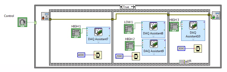
I'm trying to generate the digital output from the top and down with delays on different lines. Each daq assistant is activate single line on a port USB 6501. There more complex high and lows that I need to generate variable time difference between high and low. There is codebelow that does what I'm trying to achieve, but for a model executing high and low signal is much of your time to do it this way. I'm sure there is a better way to do it, I'm not an expert on labview so I only discovered its potential. Anyone can suggest a more effective and a quick way to do it. I would like to hgihly appreciate. Thank you!
I've not shown in the code below, but using the DAQ assistant, I initialized lines at low logic level.
-
Programming of the event with digital I/o
A Structure of the event can be used with digital I/o? All the examples I've seen show the Structure of the event used with the keyboard or the mouse. But have not found many examples showing the Structure of event used with digital input. I'm mainly looking for a link to an example. But you can provide any help will be appreciated.
Howard.
Yes, you can register events DAQmx. Look in the IO position-> data DAQmx-> Advanced-> palette of events acquisition DAQmx to start, or search for events DAQmx. All DAQmx devices support events of change detection, which is probably what you want if you have the digital I/o, in order to verify that it is supported by your device.
-
B2B generate the file with the file extension will start
Hi guru B2B.
We have a problem with the name of the output file. We have customized the java class to change the file name out based on operational needs. It works well, but recently, we see the file with the extension name from "start" are generated with size '0 '. The right files always generated with the appropriate content.
Can someone tell us what is causing this problem?
Thank you in advance,
NAFTA Li
Hi Alena
I assume you are using a B2B channel tuned to retrieve messages in a folder. Please check if this channel to listen is to have the parameter enable selected marker.
Disabling the marker Enable should avoid generating the file start in the folder.
Thank you
Arun
-
generate the table with a column of numbers from 1 to 999999999
Hi all, I'm about to generate the table like this:
Select 1 double t
Union of all the
Select 2 double t
Union of all the
Select 3 t double
But I need up to 999999999. Could you please find more simple decision?858774 wrote:
But I need up to 999999999. Could you please find more simple decision?Don't know exactly what you are looking for, but if you want to just set the number from 1 to 999999999, query below would:
select level from dual connect by level <999999999;Vivek L
-
For the complex data type, how to generate the Dll with compatible interface to C/C++
Hello
I used the Labview FPGA module to develop test equipment. Now, I need to write a driver that is to be a Dll with compatible interface to C/C++ for this equipment. So that my client who is familiar with C/C++ can call the driver without any study on labview. But I had a few problem on how to convert labview for C/C++ data complex data type. To clearly explain to my question, I have attached a simple example. (see attachment) I try to generate a Dll for the attached example VI and get the the function prototype at the head of the files as below:
' void OpenFpgaReference (LStrHandle * RIODevice, TD1 * errorIn, LVRefNum * FPGAVIReferenceOut, TD1 * errorOut).
As you have known, the type of data "LStrHandle * RIODevice" and "LVRefNum * FPGAVIReferenceOut" Labview data format are. C/C++ do not have this kind of data type and can not reconige it. As a result, I can't call the Dll of C/C++ programming language. How to convert these two data type of labview for the C/C++ compatible data format, and then build the Dll? Anyone know about this?
The answer is really apprecaited! Thank you in advanced.
Ivan.Chen wrote:
As I found in the following article:
http://digital.NI.com/public.nsf/WebSearch/FB001AA027C8998386256AAD006C142D?OpenDocument
LVRefNum is the name of resource of LabVIEW VISA or refnum, and "it is impossible to convert LabVIEW VISA name of resource or refnum VISession valid ID."
This means that external code modules can not access & control the session VISA which is open by labview. But for my purposes, I will not attempt to access this VISA extenal code(C/C++) session. I just hope that save this session VISA in the external code once I opened it in Labview dll; and pass it to the labview dll when needed. While I have not need to login again when I need to control the device. Is it possible to do?A LVRefNum is really just a single int32 value. Its meaning is useless for other environments than those who created it so that you Michael not any what in C/C++ caller but pass it back to other functions in your DLL, but this often isn't a problem at all.
You can take the following statement of the LabVIEW extcode.h headers and add them to your delabviewed header files to make it work in such a way.
#define Private (T) typedef struct T # _t {void * p ;} * T}
Private (LVRefNum);
The LStrHandle you must set a standard C string instead in your export DLL and document what is the size of the string buffer should have if it is an output parameter.
TD1 error clusters should also be divided into their parameters (C compatible) separate for all items or just to the left of suite entirely.
Rolf Kalbermatter
-
How to count the pulses with digital input on 6351
Hi all experts in Labview,.
I just got my USB x series 6351 and it works fine, but I certainly lack of labview skills to use it to its full potential.
I would like to read digital pulses with several digital inputs and count the number of pulses each T interval in time. All impulses that I entered on any edge of the clock are not synchronized and can occur at random times during the tests. Basically I have an oscillator of square waves can I modulate the frequency. I don't want to use the meter as inputs as I'm limited to only 2 entries (if I use the option 2 input meter for metering of pulses or frequency). The input frequency can range from 0-1 kHz and goes 0 - 3V. So not too fast, and I shouldn't make too many mistakes trying to get the count of pulses and then back out the frequency in accordance with article ni.com on counters.
I would like to read the 8 digital input channels and get the number of impulses for each channel. I searched high and low for help online but can't find examples that have been useful. Anyone have any ideas on how to go or direct me to a resource? Thank you very much in advance!
Are you worried about getting the number as a physical operation timed? It would be nice to acquire a digital waveform and then postprocess on it to detect how many events took place? I've attached an example that shows how you can accomplish this. It reads a digital waveform and then uses a detection of crete VI to determine how many pulses occurred. Should be a few adjustments to your particular signal. The VI I use seems to count events twice (probably count each edge), so counting it gives should be reduced by half in order to work.
-
Generate the ADF with Eclipse jar file
EIS,I followed the guide to use Eclipse as the tool to develop ADF related stuff, found here:
http://www.Oracle.com/WebFolder/technetwork/Eclipse/ADF/gettingStarted/tutorial/ADFwithOEPE_1.html
Everything is fine, and I've created classes, references, the flow and the pages. However, how to deploy such things in a jar file? There is an option in the JDeveloper, however, I can't find any way to do this in Eclipse? You need a profile I can use, or similar?
The thing is that I've developed things like extensions of the IOM, and so I need to add the jar genereated file to the war file named:
Oracle.IAM.UI.Custom - dev-starter - pack.war
by:
oracle.iam.ui.custom-dev-starter-pack/WEB-INF/lib/the-generated-jar-file.jar
Hope someone has a clue about what to do, because I really want to use Eclipse and JDeveloper.
Kind regards
Vegard
Looks like some doc links are broken. I found the tools Oracle ADF that describes what it takes to generate an adfLibrary in eclipse, but I don't know for what version this document is intended.
Timo
-
generate the view with the union
Hello
I want to create a view
CREATE VIEW ViewTest AS
Select ID, Number, to_char (City) in the Fi
Union
Select 0,0, "of the double
But I get an error message:
shall appoint this expression with a column alias
What is the correct syntax? I want to get all the rows in the table 'fi' one another line with id = 0.
The select works, but the creation of the view, then I get the error message
Best regards
Thomas
Hello
First of all how you can create a Fi table because you can't use number as column name? It is not appropriate for the conventions of name of column in the oracle.after remedy
and
Error is very clear and it says you have to. "shall appoint this expression with a column alias.
When you create the view, you must specify a column name for the expression in the first statement as follows
CREATE VIEW ViewTest AS
Select ID, No, to_char (City) city_name fi
Union
Select 0,0, "of the double
Yasin
-
generate the list with step 30
Hello
my need is to generate lilies at 30
for example:
ID
30
60
90
120
...
How can I do this?
Thanks in advance.
Select the level * 30 double
connect by level<=>
----
Ramin Hasimzade
-
How can I more easily generate a pulse of digital output of finite length?
Hello
I need to open and close the two pneumatic valves using a TTL output (without load current or the output power) using a PCI-6280 or PCI-6601. The valves must open almost simultaneously and closing after different amounts of time elapsed (millisecond level timing, maybe 100 microseconds-level timing at worst). My current plan is as follows:
-Create a task with two digital outputs (type of waveform) and another task with a counter that generates a frequency set by the user (I know I can use the generator frequencies on one of these cards, but I would have preferred a counter - the best selection of frequencies).
-Wire the output of the counter at the entrance to clock two digital outputs.
-Output of the meter is digitally triggered by another digital channel which I use to control if the pulse goes out. Through its counter node, it is programmed to be redeclenchables.
-Two digital waveforms are drafted who have both consist of unique active high pulse (i.e. signals go ' down (for the amount of time user-defined) - low ".")
-These signals is written to their respective ports and their tasks have started, as is the task of the meter.
-Whenever the user wants to open taps, digital triggering is sent up and then back to low (this can be done with synchronization software, because it is not exactly when the fire valves). Whenever the user wants the valves open for a different period, different digital waveforms are generated and written in the buffers of the digital output channels.
My problem is that it looks like a lot of effort for me to go and I wonder if there is a much simpler solution, that I don't know everything. You can program a computer to produce a pulse of finite length? Is there a faster way to program a digital output for that channel?
Thanks to anyone who responds to their help.
It is certainly instructive. Thank you.
The thing is, I have only six total counters to work with and I have a lot of time to do things. To use these solutions, I would need to use 4 or 6 account counters required to my needs.also that I would need to synchronize their departures.
Overall, I stick to my method for now - less system resources and synchronization can be don by using the same meter of finished output clock and not to use a trigger to all.
Once again, thank you for your help so far.
-
digital triggering of stop/start of analog data acquisition
I want to use a signal from a digital line to start and stop analog data acquisition. The signal can change levels several times during a race of the VI so I have to start and stop several times data acquisition and store each session data in a different file.
I tried to play with the following screw: digital triggering of break, DigitalStartandStopTrigger and ContAcq_DigTrig. None of them doesn't seem to work for my configuration. I also do continuous data acquisition so I can't use a reference. I use PCI 6259 DAQ.
I used the "P0" pins rather than PFI pin on the grid BNC-2090. I know... stupid enough.
-
DMVPN with digital ceritificates and Hub acts as a CA server
Hello guys,.
is there anyway to configure the DMVPN with digital certificates and change the router Hub to act as a CA server?
Thank you
Yes, you can do it, go ahead and set up your router, Hub, with the normal DMVPN configuration so that it becomes the hub. After doing that follow the link below to add public key infrastructure server features:
http://www.Cisco.com/en/us/docs/iOS/12_3t/12_3t4/feature/guide/gt_ioscs.html
And to register for the rays on the hub, use this link:
http://www.Cisco.com/en/us/Tech/tk583/TK372/technologies_configuration_example09186a0080210cdc.shtml
Remember that regardless of the router Hub being the authority of CA, you must sign up for itself to allow the IKE PKI authentication.
-
Problem with keyboard triggers
I have a character (head only) set up in Photoshop, everything works as expected until I try to add a second version of the head with keyboard triggers angry.
When I activate the trigger, the swap of heads, but the new Chief has no eyebrows on caterpillars or movement of the mouth. The head itself is going to scale and rotate, but none of the strokes on the 'traded' head work.
I compared it to the Wendigo.psd file and cannot determine what exactly I'm doing wrong; everything seems to be done in a similar way.
Here's what my layer Setup looks like currently. Thanks for any help!

The behavior Face is looking for a head as its base, so we do not currently have a way to replace a different set of secondary face through the key elements of. However, this should be possible by creating separate views (for normal and angry) and having the head structure, it contains, then application face and Lip Sync to eyesight and removing of the top-level puppet puppets. Discover the project examples of character animator (character animator examples) and specifically the puppet of Wendigo in '02. Wendigo scene' to see how it is implemented.

Maybe you are looking for
-
iMac, end of 2015 iPod 5th generation Touch. Since arriving in a new home several miles from our previous stay, location Services was unable to determine my 'current location '. I am somewhat isolated here and not in the scope of other WiFi networks.
-
trigger data acquisition on a file writing
I have trouble getting my DAQ to write data to a file based on an external analog input. The challenge is that the analog input signal is only about 1 ms long and I use an old NI 9172 cDAQ. The analog input is not very active, so I want the program
-
Usually in the past when I got docs who won't open, a menu will appear asking what program I want to use to open it. This does not happen in this case. My daughter uses a new laptop that obviously has a lot more progs installed up-to-date. I can't
-
original title: computer freezes When I play a game on facebook called words with friends, my computer freezes the game after a few movements. Why?
-
Daily 5 yellow flashes Alien Alpha
Hello I just got my Alpha Alien renovated taken Dell last week. At first I started it perfectly without any problems. But after that, I do power drain to start the operating system. Power Drain links below: en.Community.Dell.com/.../19659357 It's qui