generate the output waveform on 6259
Hello
I would like to generate signals of "simple" digital square output 3 6259 NI Board of Directors of 80 Hz.
Because of the wiring of my test tool driven 6259 Board, I can't use the output of the meter, but I need to plug into 3 output lines.
I re-used an existing vi and made by a subcontractor, but the generated waveform on my DUT does not have the expected frequencies (although it seems OK on the generated graph). Indeed, there are some forms of square waves, but not continuously. A sort of "pomade" and "elected" frequency does not match the measured frequency. If someone has an idea to help me, I have not experience on labview yet!
Thank you!
You have 4 unique digital States aimed at bike. Each cycle produces 1 full period of each of your square waves. If you want the output to 80 Hz, you must set the sample to run 4 * 80 = 320 Hz clock.
The other thing you see on the scope is that there are short bursts of pulses with parent long time between bursts. The calendar during the bursts are what control tasks. The time between bursts is caused by using the button "run continuously. Also that according to them, you complete vi almost immediately rather than waiting until they run awhile. Put an end to the execution of vi initiates self-cleaning of LabVIEW. These things represent the time brief burst and the ISH between bursts.
-Kevin P
Tags: NI Software
Similar Questions
-
How to generate the output xls by a button in oracle apps
Hello world
I have a report that gives me xls output when I run the program at the same time.
I have a custom form that has a button to call the program contributing to print the report.
I realized this from here
But this code works just fine if the report output format is pdf.
If the report output format xls this code generates pdf output
but my requirement is to generate the output as xls.
Please any one help how to achieve this.
I use EBS - 12.1.3
Oracle made and reports 10g
Concerning
Paul>
If the report output format xls this code generates pdf output
>
Looks like that pdf is out by default in the template definition in the xml editor RESPso for r12 use FND_REQUEST. ADD_LAYOUT as example
...
v_request_id   number;
xml_layout boolean;
...
xml_layout := FND_REQUEST.ADD_LAYOUT('XXCUSTOM','XXCONCNAME','en','00','EXCEL');
v_request_id := fnd_request.submit_request(application => 'XXCUSTOM',
                                           program     => 'XXCONCNAME',
                                           description => NULL,
                                           start_time  => NULL,
                                           sub_request => FALSE,
                                           argument1   => p_date
                                           );
See also http://andyblg.wordpress.com/2012/08/23/run-concurrent-program-twice-with-different-layout-r12/
-
No contents do not on mobile devices after generating the output Multiscreen HTML5?
I use a trial version of RoboHelp 10. "I created a new project and used the screen profile: Android_Galaxy_Tab and the screen layout" Android_Tablet_Layout and HTML5 generated the output. I navigate to the folder on my computer and click index.htm and it appears in the fine Chrome browser, but I download the correct files to my web server (via FTP) and search for web files and do not appear in the TOC. As well as on mobile devices. The web files are here www.superdesigngirl.com/android_galaxy_tab/index.htm. I have to publish files on the web through RoboHelp? Is this a known issue? I put something wrong? Help, please. Katherine.
The only reason that I can think of for what you downloaded not to work as it does on the spot, it's that you have not actually downloaded everything. First thing so we must compare local production and what is on the server, as Jeff has suggested.
Same search is a failure so I suspect that not all subfolders in the output of Android has not been downloaded.
It might be useful to create a webhelp layout and download to see if it works.
See www.grainge.org for creating tips and RoboHelp

-
Generate the analog waveform based on the data file
I want to create an analog voltage output that follows I have a data file (excel, csv, text (which is easy)). The data file creates a waveform with equal time between steps (dT =.0034 sec). After the output through all the data points, I want it repeat indefinitely.
What is the best way to create the waveform of a data file?
To create a type of waveform data, calculate the dt by subtracting two values in column 1 and get the array of Y from column 2. If you save the file as a comma separated or tab text file, you can then use the spreadsheet file read. After obtaining a 2D array, you would use the index table and the subset of table functions.
Assuming you use a capture card data OR for the output signal, you can pass a type of waveform data to a writing DAQmx and set for the generation of types.
-
Why some OCD is not used to generate the output?
I use RoboHelp 11 on Windows 8.
I use a print single source layout that uses a table of specific contents. However, when the output is generated the same set of topics are included, none of which are in the selected table of contents. I'm mystefied, and in the hope that there is something that I forgot to select Properties.
Here's what I use.

And here is the created files:

The TOC file is empty. The 'Expédition' file contains the contents of a subject who is not in the table of contents.
Help?
AHA. Found the answer in the article by Peter Grainge (printing problems). Thank you, Peter!
-
This is a question and a suggestion...
I would like to be able to precede or add if it works, the command line in the output file that creates the order.
Example:
I run dcdiag with switches, etc. and create an output file of results that gets saved or sent to a person or just put it in a folder. Of course, it could be that someone else ran the command and then sent the file. Anyway the problem is the same - what was the exact command line that has been executed to achieve these results?
Question:
Is there a known way to do from the command line that I can apply to any command?
Suggestion:
If this isn't the case, then I would suggest MS to include this function in all the BACK and PowerShell commands able to produce text output.
If all goes well they monitor this forum and find it's a great idea and send me a check (pinky in my cheek) a meeellion of dollars. Then I and I alone will rule the world.
Here you go:
d:\>format i: / FS: NTFS > format.txt
d:\>echo i format: / FS: NTFS > format.txt -
Generate analog output waveform finish on request
Hello.
I have a VI that reads in two data channels (400 samples at 400 Hz), calculates the characteristics and classifies data based on a model. If the class is a certain State, a Boolean value called "Détection" is set to True. A second Boolean value called "Stimulation" is also set to true and flip flops and turn off every second up to what the "detection" is more true. Now that I am reading and classify a second data, Boolean values may only be updated once per second. I am wanting to generate output "Stimulation" Boolean is true analog. I had been accomplish this by generating a sinusoidal signal all the time and write to a buffer in a separate loop (500 samples per writing @ 10 kHz) and multiplying by zeros if "Stimulation" was false. I have a code that more or less does what I want, but there is a delay of ~ 200ms between 'Stimulus' is set to True and AO generation, and I feel like it could be simplified. I was wondering if it would be better to generate a waveform finished and trigger to write with the Boolean value of 'Stimulus' (i.e. write 1 second of a sine wave to the changing state rather than write 20 sections of a sine wave in a second, while the Boolean value is True).
Y at - it a good way to do this with daqmx functions? (Generate a waveform of defined duration when a control changes)
-
Acrobat Pro XI V11.0.2 - Word 2010 to PDF Convert is unable to generate the header text
Hello
Following the recent update to V11.0.2, the converter of PDF of Acrobat to Word 2010 fails to generate the output document properly. Missing on the part of the text of the Word header box.
However, using Acrobat XI through the 'print to PDF printer' seems to generate the output correctly file.
System is Windows XP - SP3 with Office 2010 (and all current updates), Acrobat Pro V11.0.2
Example Word source and PDF file are available, if anyone can find a way to this web interface allows to post examples.
Colin Butcher.
We have the same problem. We have set by going to Options and uncheck "enable accessibility and reflow with containing the tag Adobe PDF '.
So, we will not have every time that Word, we went in Arobat-> preferences and unchecked this setting.
Aaron
-
Why the table in the output of MT complex waveform modulation FSK 255 elements missing?
Hello! I posted my question in the LabVIEW forum but an application engineer suggested I post here. I'm new so any help would be appreciated

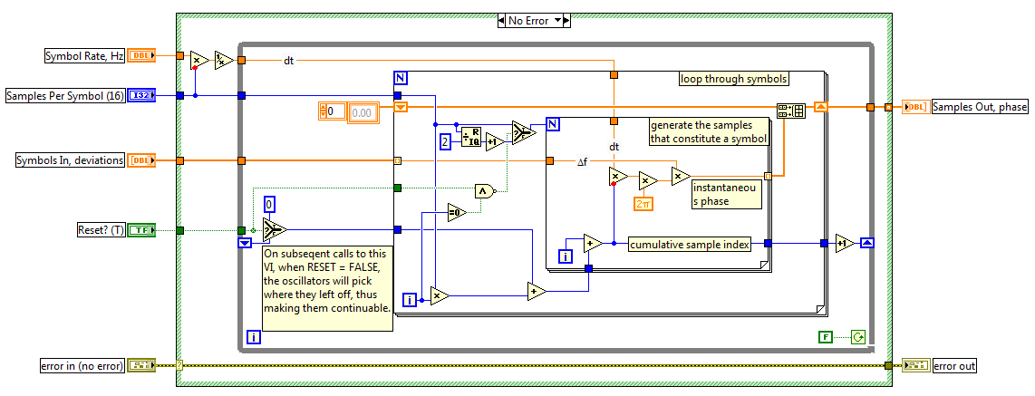
I use this example FSK in LabVIEW (VI is attached). As it can be seen in the block diagram, the number of samples by specified symbol is 512. If I run 2 - FSK, I have 1 bit per symbol. So I if I have 128 bits, 128 symbols. and if I have 512 samples per symbol, I expect 65536 samples/elements in the complex waveform of the MT output modulation FSK. However, I get only 65281 elements in the table. There are 255 missing items.
If I run 4 - FSK and have 128 bit or 64 symbols, I expect to 32768 in the table. But then again, I'm running out of 255 items and get 32513.
Am I missing out on something? Have I misunderstood something? Thank you very much for your help.
I get the same results as you!
I Dove a little inside, and it seems that the code that generates the symbols, two layers down, which reports an explanation to this.
If you open MT modulate FSK.vi, then mod_FSK modular Phases.vi discontinuous to generate in the discontinuous case of the structure of the case, you will see the following code.
You can see that when Reset is set to True (the default) and the external-loop for is in his first race, the inner-loop for work (samples per symbol) / 2 + 1 times (in your case, this number is 512 / 2 + 1 = 257.) Subsequently, the inner-loop for runs with 512 for each outer loop for iteration. This means that the first round fail to 512-257 = 255 samples, which causes the total to 255 less samples.
I don't know what is the motivation behind this design. As a test, you could connect in a constant False to Reset of the MT Terminal modulated FSK VI, which causes all the samples to generate.
Hope that clarifies it.
-
delay between the identical waveforms generated
Hello world. I want to generate tension by the use of the NI USB - 6353 X. When I tried to use the vi 'Voltage - finished output.vi' example, I realized that there is a period of time between two generated waveforms. It is an undesirable situation for our application. Why is this delay happens? How to generate at the same time?
VI of function generator based on there is an entry called Signal of Reset. Than the true value. What is happening is that your second wave comes to be a continuation of the first. As the first waveform settings say he needs a little more time, you get this time dead at the beginning of your second waveform.
-
Generate analog output with the software "Timing" on 6009
I see that the 6009 does not support the synchronization of the internal clock. We need to generate an analogue waveform which changes very slowly, it performs a cycle every 10-20 minutes.
I saw an old post on the use of calendar software, but can not find a way to do this using SignalExpress.
Any ideas or references to examples of messages, etc. are greatly appreciated.
Analog output clocked by the software (DAQmx) in SignalExpress
I hope this helps.
-
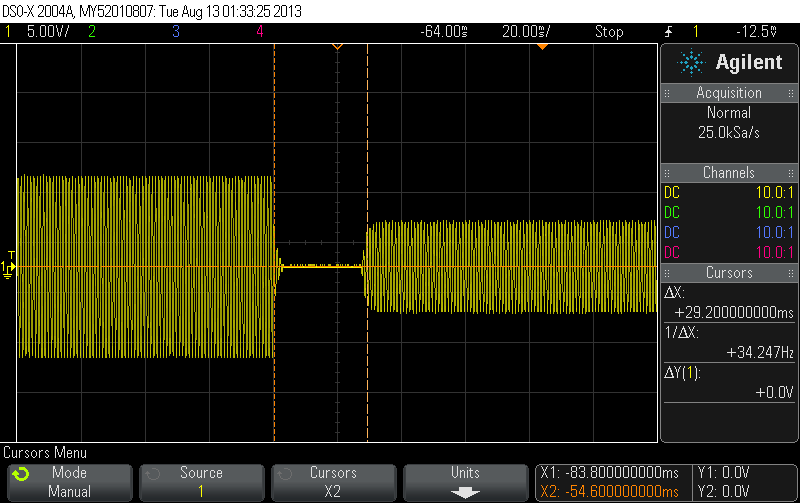
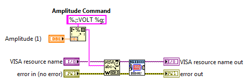
Change the amplitude of the Agilent function generator output while the output is on
Hello
I am writing a program to scan the amplitude of a sine wave of a function (Agilent 33210 a) generator output. I have two sets of pilot example: Agilent 33xxx and HP33120a (the first one uses VISA, IVI 2 uses).
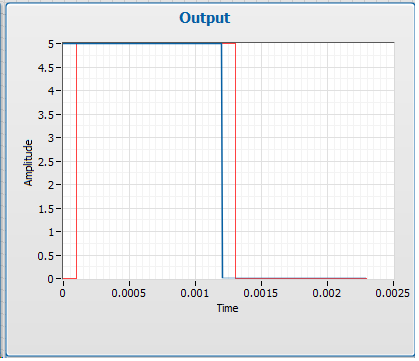
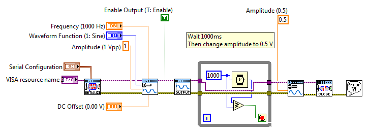
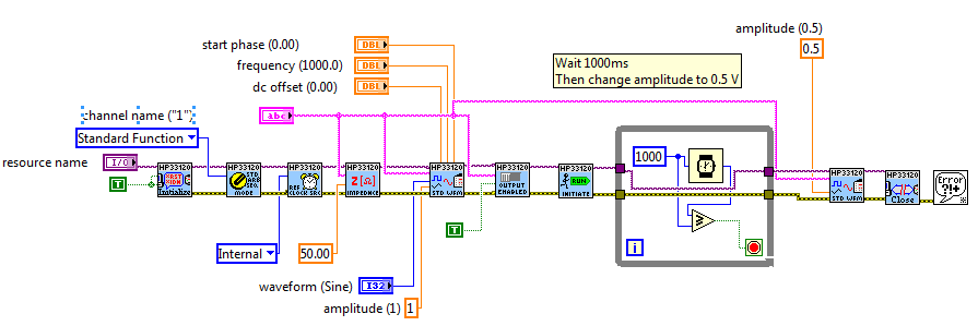
Using the example of driver code, I changed to generate a sine wave to 1Vpp, wait 1 sec, and then modify the amplitude of 0, 5V. I have attached the images in my field that show what happens when I do that. The two examples cut first exit before Relighting with a different amplitude. 33xxx driver takes 140ms for change, and has a strange burst between the two signal. HP3120a driver takes 30ms and cleaner air.
Agilent 33xxx example using:
\
HP33120a example using:
I would like to have the change is instantaneous. When you use the generator manually, I can turn the button and change the output in real-time without delays.
Thanks for the suggestion of Mateus, but I am trying to automate this process of my best. Change the VISA pilot is the direction I want to go.
Thank you crossrulz... I wrote a new issue VI of the Standard waveform VI set up so that it simply writes the new amplitude control and none of the other things. Worked like a charm! Now the waveform changes amplitude without turning off the exit. I also checked to see if re-defining the shape of sine wave (even if the original is also sinusoidal) was the cause of the delay as you suggested, and you were right. Thanks for the help!
-
Distribute the data output waveform of niScope Multi Fetch Cluster
Now divide the data in a table 1 d of the clusters. I use a PXI-5421 function generator and a PXI-5122 digitizer. The output data of retruns NiScope Multifetch Cluster.vi of the waveform as a table 1 d of the cluster of 3 elements. This table contains the information of channels 0 and 1. I am trying to extract information from component waveform of each channel, so I can work on them a wave two re - assemble. Can someone point me in the right direction? I can't seem to find the right tool in the tools of painting or a cluster of. Thank you.
Jeff
You just use a table of Index and a Unbundle by name or Unbundle.

-
Import MATLAB generated the file ascii in the Analog Waveform Editor
Hi all
I tried to create signals by the Analog Waveform Editor. I have some Waveform generated from MATLAB and recorded as ASCII files, following the instructions on this Web page OR, but it did not work properly. For example, if I produce a column to fill with 0.5 and import the file into the analog signal generator, all I get is a huge series of random number. I missed a few steps in the import of the waveform?
Thank you!!
Just for your reference, I could almost in half the size of your file just by saving as .hws. Also to answer your last point, you may have issues opening / importing your .txt file because it may have been opened in another program at the same time. Make sure that you have closed it in Notepad or Excel or other programs which may still be locking on the reference.
Kind regards
Jason L.
-
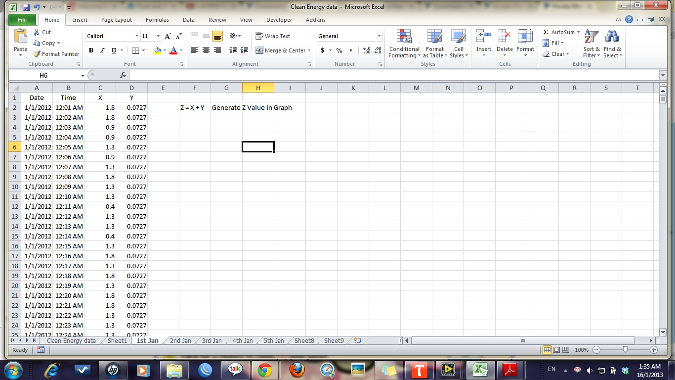
Generate graphic output of the formula variable entry in the time
Hello
I'm new to labview but I have some knowledge of basic and I have a month to carry out a project with labview. So, please guide me how to do the following.
Currently, what I want to do is to generate the graph of output of a formula that has variable contribution on time.
Please find the attached photo for my excel sheet.
the value of X and Y which are entered and Z are out. for example. Z = X + Y (X and there vary in time)
I want to show the value of Z output graphics over time in column A. RELLY APPRECIATE YOUR HELP...
 tthanks
Try this...


Maybe you are looking for
-
ConfigFree does not work on satellite A200
Help, please.At the start of my laptop, I get a message:NdsLoadString0 has error (not found INI File: C:\Program.) Adrian big
-
Need drivers for Satellite 1800 750
Hello I bought used Toshiba Satellite 1800 750 but the sound is very low, how increase the volume?Also - what someone could point me to a link to download the drivers for above?Any help would be grateful received.
-
Hello everyone First lenovo forum poster long time fan, I bought a laptop lenovo workstation p50 with a 500 GB drive, while I wait to happen I am looking to buy an ssd nvme im m2 wondered what one of the locations below would use the ssd nvme?, do I
-
c drive is not available after refresh of windows 8
My computer won't start so I decided to update it.
-
I'm running a (main) EA8500 with a fiber using LAN and WLAN modem (no comment box) and all is well. It's a great piece of equipment. I intend to set up an another (secondary) EA8500 for young people and their friends. I would like to the secondary im