Generator functions agilent modulated the amplitude of the voltage so that the signal
Hello
I'm new on the Labview.
I need to provide a series of tensions with increases step on my device and it repeats again and again.
For example, (5V 0V to 10V 0V 0V 15V) * 5 times
In the past, I turned down on the generator Panel of Agilent 33220 functions by myself.
It's stupid, so I will try to use the Labview to do the same.
I have download the Agilent 33220 Vi function generator has and write a loop for to do this. It can work.
But I found a problem. Each change of amplitude voltage, generator Agilent 33220 A functions will cease to exit and then output the new value.
Because this short period of no output voltage, the dynamic behavior of my device will be destroyed.
How can I do?
You made a classic mistake. You have placed the Initialize and close inside the loop. The Initialize will, by default, perform a reset feature, which disables the output. Initialize outside a loop, do your stuff inside and close the loop.
Regarding your code: I strongly recommend looking at the model of ramp function. It seems you want to increase the parameters of voltage to zero between the two. This can be easily done by creating your rising tensions ramp and then creating another matrix of the same size zeros and interlacing then the two tables. This will give you a complete range of voltage values, without to need two loops and determine what step you are on, etc. etc. For example, the following code will give you 5, 0, 0, 10, 15, 0 sequence fairly cleanly:

In addition, never perform a comparison of equality on the floats. If not, you owe me nickel one another in my retirement fund.
Tags: NI Software
Similar Questions
-
How to generate a pulse with the signal generator?
Hello
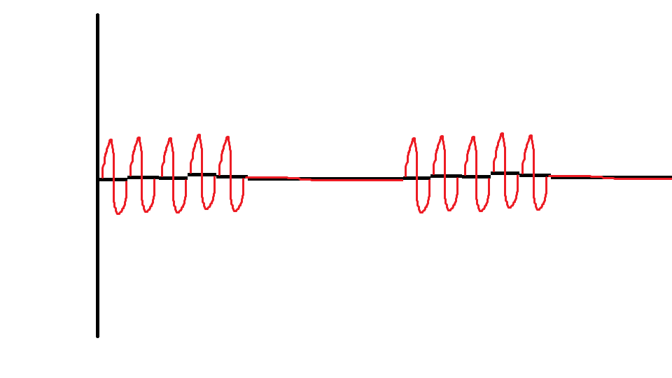
I would like to ask if anyone knows how to use the Elvis platform to generate a regulated pulse wave?
It should look roughly like the picture above. A sine wave with the regulation.
Anyone who can answer my question please respond to my post.
Thank you.
You are using LabVIEW to generate the waveform or using the Soft front panels? In LabVIEW, you can use the express VI generator function and specify the Type as "Sine". Then, simply change the amplitude of the sine wave. During the actual pulse, the amplitude would be what you want (i.e. 1 V) and while the pulse is idle, set the amplitude to 0.
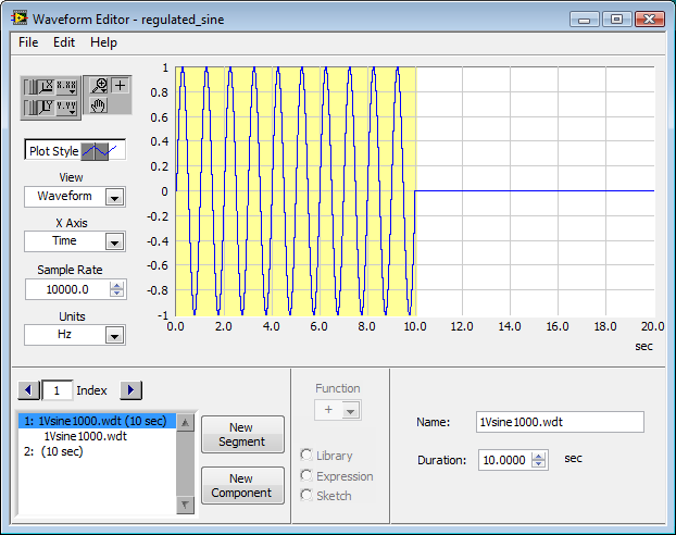
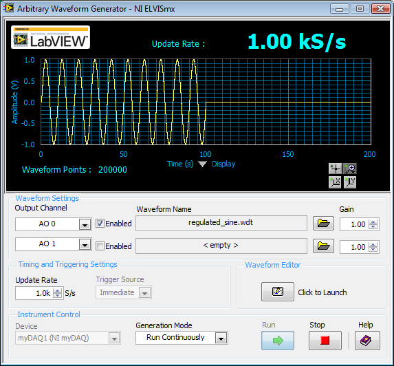
If you use the soft front panels, you can use the Waveform Editor to create a waveform that includes a sine wave for the length of your pulse and then the values of '0' for the rest of the time. Then use this waveform in the flexible front of the arbitrary signal generator. Simply create a component of sine as the first part of the wave and then add another element to a level DC '0' for the rest.
-
Generator function defined by the user (normalize data points)
Hi all
You can use the function Scale1D to the Analisys Advanced library.
-
Results of increasing frequency generated unexpected behavior of the signal
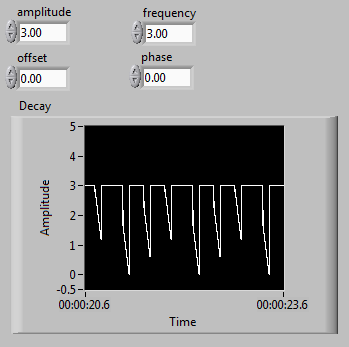
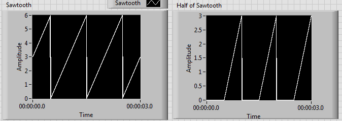
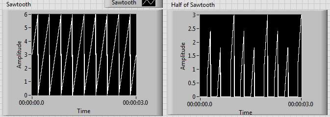
I'm generating a composite using a sawtooth wave, square, signal that produces the desired signal as shown on the left. Unfortunately, when the increase of the frequency beyond 1 Hz, I get undesirable results as shown on the right.
I tried to edit the news of sampling with no luck. I have also tried different methods to produce the desired signal. I noticed that before one of partial components of the final signal enters a relay, the increase of the frequency doesn't create unexpected results. Although, after its passage through a relay, the error starts happening. It seems that the relay is not suitable for higher frequencies, but I can't fix this unexpected behavior.
Frequency of 1 Hz:
Frequency of 3 Hz:
Another method that I tried was to use the "simulate arbitrary signals," even if I was unable to find a way to increase the frequency of the signal that results.
In addition, the signal has this grainy nature that I would like to make it smooth and continuous. Is this possible? I would like finally to reach a frequency of a few kiloHertz.
I have attached the VI.
Any help would be greatly appreciated. Thank you.
The problem has to do with the size of the block and when the relay actually sees the saw tooth cross the threshold.
Solve it, to perform a point-by-point check and build our waveform personalized to each iteration.
-
Synchronize the ctr1 at ctr0 (generate outputs freq) via the signal of export
I need help to configure the output channels of meter on my card pxi-6723. Here's what I'm trying to do:
-have the possibility to synchronize the ctr1 exit toward ctr0. Note: ctr1 must begin on edge increase or decrease output ctr0.
-be able to change idle, freq. etc for each of these outputs
A sample that I worked on is attached. It works except the ctr1 output is trolling by cycles of 1 to 1.5 (according to a State of rest, edge selections). This delay is due to me having to put the slave (ctr1) task run after the masters. Note: The reason for this was the task of enforcement of crt0 (master) was the origin of the false triggers when exporting the trigger signal.
Its there a way of software trigger ctr0 OR delay its release until both (ctr0 & ctr1) 'perform tasks"have been launched?
Hi groz,.
I have not tried, but I expect the following sequence to prevent false triggers:
DAQmx control Task (ctr0 task, Commit)
DAQmx Start (task ctr1)
DAQmx Start (ctr0 task)
Principal ctr0 has it on its state of rest.
Also, I think you can do this trip without using a PXI_Trig line. To Start.DigEdge.Src the ctr1 task, specify "Ctr0InternalOutput". (To make the Terminal Ctr0InternalOutput appear in a Terminal of DAQmx e/s constant, right click on the constant, select "I/o name of filtering...) ("and put a check mark next to"Include the advanced terminals").
Brad
-
Why do I get error 200524 for the generating function 2 code example?
I get the following error message:
Error-200524 occurred at the generating function 2 channel_lv86.vi
Possible reasons:
Scripture cannot be performed because the number of data channels does not match number of channels in the task.
When writing, provide data for all channels in the task. You can also change the task so that it contains the same number of channels as the written data.
Number of channels of task: 1
Number of data channels : 2Task name: _unnamedTask
When I downloaded and ran the 2 channel here code: https://decibel.ni.com/content/docs/DOC-3545
I have a card pci-e DAQ 6259 and a block BNC-2110
Why I get this error?
When I open the VI I selected ' Dev1/ao"under physical channels. I tried all the other options (a0 - a3) which gave the same error message.
If you have 2 channels in your data (as indicated in the error message), then you must choose 2 channels in your task control (the error message says that you have selected only 1.)
You saw in the example how they were able to identify the 2 channels of analog output?
-
Are the modules the SMEs as the pop ups?
Your 'help' sites speak of Add-ons. This morninng, that I could not open an E-mail because the quick scoring on screen says that my "pop-ups" were blocked.
Hi Marie-Céline,
Add - ons are not the same as pop-ups. Find and install add-ons to add functionality to Firefox gives you more information on the modules. They are similar to applications that add additional functionality to Firefox. The blocker is simply a tool used to prevent websites to open a new window without your permission. If you encounter a problem with the blocker, take a look at the article the blocker, exceptions and troubleshooting settings. It will show you how to use and manage the popup blocker in Firefox.
Hope this helps!
-
Generated sending the signals to a remote computer in a network
Hi guys, I am new to Labview and need help. I use Labview to generate a voice modulated signal and I want to send this signal to a remote computer (real-time). How can I do this, so that this voice signal is regenerated in the remote computer?
Hi Sarah, thanks for the advice.
-
Hello
I do a work already done by others: implementation of a Wrapper to SQLite LabVIEW, I know how to do with .NET alas I would do that c, mainly for purposes of performance and my pointer poor knowledge is kinda make me stuck.
Some information is kindly provided here:
What I want to do is just to open a connection to an SQLite database (if not existing does not, the SQLite engine will create the embedded database and the corresponding file to save the data and everything). The function to perform the operation is indicated in the page below:
It seems simple enough:
int sqlite3_open(
  const char *filename,   /* Database filename (UTF-8) */
  sqlite3 **ppDb          /* OUT: SQLite db handle */
);
int sqlite3_open16(
  const void *filename,   /* Database filename (UTF-16) */
  sqlite3 **ppDb          /* OUT: SQLite db handle */
);
int sqlite3_open_v2(
  const char *filename,   /* Database filename (UTF-8) */
  sqlite3 **ppDb,         /* OUT: SQLite db handle */
  int flags,              /* Flags */
  const char *zVfs        /* Name of VFS module to use */
);
However, I'm struggling a bit on the following type:
sqlite3 **ppDb /* OUT: SQLite db handle */
And I'm not really sure what type to use when calling this function of LabVIEW
Any idea, I guess it's really easy, but I'm not really used to have a type which is I guess the DataInstance but as it is not clearly explicted in the C library function prototype interpreted LabVIEW (InstanceDataType is logical but not sure if) I'm not really sure what I show in the screenshot is valid or not.
My VI seems to work like a charm, but am not sure if I'm doing something wrong.
Another prototype that I have no idea on the appeal proper LabVIEW is the close function:
I would like to get this straight, usually a parameter has a name, right? but seems not:
int sqlite3_close(sqlite3*);
int sqlite3_close_v2(sqlite3*);
Similarly no idea about setting up for this one... must be regarded as the free forum like the one calling this function is... but I don't send any object?
Really confusing...
sqlite3*
I might sound really stupid, but if someone could point me to a few tracks, I'd be really grateful for that.
Thank you
Ehouarn wrote:
However, I'm struggling a bit on the following type:
sqlite3 **ppDb /* OUT: SQLite db handle */
And I'm not really sure what type to use when calling this function of LabVIEW
This parameter must be an integer of size pointer, passed by the pointer. No matter whether it was signed or not signed. The SQLite library will allocate memory for you, then put a pointer to this memory in full the pointer location as you go.
Regarding the close function, you must pass the same integer pointer, but this time he passed by value (because it is referenced with a single *, not two). There is nothing wrong with the documentation by omitting the name of the parameter. For the application of a function prototype, the parameter name is without important, since everything you need to know is the type of data. How the service chooses to refer to this setting internally is irrelevant.
-
Calling a function only when the State is active
I turn to find the event just to call a function only when the status is active. In fact, I created a State to display the 'product details' click and once the system changes to this State - I have to perform a function.
Here's the context:
Let's say that you are on the home page where you will need to click on a product to see details. By clicking on the product, the State to view the details of the product will be activated and a variable inside the new state you will receive all the data (from the class of product). But I discovered Flex run all States at the beginning and we need to watch how declare our function to make sure that we do not have a null to a variable/object reference. Given that value is moving to the State only when the click event to occur, the process of globalization, execution of all States at the beginning will not have any value yet (for the specific product to deal with in the State of the productDetails). So I can't use creationComplete to perform a simple function like setSpecs(), where all the values (for example, width, height, circumference, diameter, price, etc.) will be instiate specific labels.
What event to use to call a function internal once we are in the State? Just using the creationComplet and stated if he check the currentState = that I have to work on is not enough. I tried 'activate', 'show', 'enterStage' and many others, but without success. I tried to search the Internet, but it seems that this problem is not popular enough to generate sufficient results.
But I know that it is possible in the case otherwise it will be is not logical and since Flex work very well with the event, I found the right event. It's something basic I know, but when you do not know, it seems difficult to find! ;-))Thanks Greg!
I agree, this is a better method. So I'll change my SENSITIVITY to use viewStack instead of the State. But the problem persists what that, if we use the viewStack State to launch an event only when the State/viewStack is displayed on the screen.
I found something that works very well for me: updateComplete.
First of all, I found this before reading your information about viewStack so it worked very well for the method of the State. That I decided to do a test to viewStack and made the necessary changes to the code to reflect a viewStack navigation and make sure the updateComplete was not within my component (stateProduct.mxml). The system was not able to view the specification as the setSpecs() function was not instantiate when displayed. I added the updateComplete = "{setSpecs ()} ' and everything worked great!" So I conclude that no matter if you are using a viewStack State, the updateComplete event can be used to run or functions only when the component is displayed on the screen.
Now, I have to make my transition between the State working with viewStack effect! ;-))
Thanks to Greg for this useful tip!
-
HP FIRST: function Inverse on the question of the HP Premium
Hello
I was wondering if anyone new how to find the inverse of a function expression on the HP Premium algebriac.
This can be done on the Casio Class Pad using the inversion function. Watch the video link below.
https://www.YouTube.com/watch?v=8jSKf8OJaW4
So may my question a similar thing is done on the FIRST HP.
Concerning
Arthur Rappos
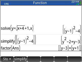
The forum said that my image upload is "pending approval". I hope it shows up soon. If not, here's a link to it on my web server: http://holyjoe.net/images/isolate.png
In the meantime, you can find the inverse function of almost no matter what there simply by solving this equation of x using the command solve in CASE. This is sometimes referred to as "isolation x". For example, if y = 1 + 2 / x, you can find the inverse function in case of premium by typing this:
Solve(y=1+2/x,x)
This isolates the x the other side of the equation, which gives us x = 2 /(y-1), which shows the inverse function, we were looking for.
The command solve can insulate almost any variable from almost any equation. It is very powerful.
-
How to stop up to generate a waveform of the entire cycle when click on the stop button
Dear engineer OR,.
I have generated three AO signals to control my scanner and data acquisition. Two ramp signals is to control the galvanometric scanner (x and y). A TTL signal is to trigger the acquisition of data. Whenever I click on stop, the ramp stops every time that it is when the button is clicked, what causes a voltage jump when will resume the program again because the ramp will start in the place original (this jump of fast voltage can damage the galvanometric scanner). Could you please give me some suggestions on how to stop after only a waveform of cycle whol's over? The VI I used is attached. The FLIM control.vi is the main vi include Subvi Galvo control.vi
Thank you very much!!
Hello, dgql!
From a point of view purely programming, there are a few ways you could implement this.
(1) create a conditional stay:
You can add features to the code such that, once you reach the stop button, the code checks the value of your signal before you actually stop the VI. In pseudo-code: "If the signal is > 0 and less than a certain value, stop." Otherwise, keep the control of signal until the value lies in this range. »
(2) to reset the signal from the ramp at each start of your VI. This may or may not work with your application, depending on whether you must have the previous value of the ramp carried over.
Let me know if these are of no help!
-
Easy way to locate the function used on the diagram by name?
Is there an easy way to locate the functions used in the diagram under the name of the generic function?
I have user appears somewhat to the user on my diagram functions to help me debug a difficult sequence of agross events live multiple now that it works, I want to go back and disable most of these postings. Most of them went up to now within the layers a little structure and is not easy to find.
So is there an easy way to get a list of where these functions are used so that I can quickly go and edit them?
I find the function is with the display hierarchy that does just what I need.
Thank you.
-
I am facing a problem with the beep.vi. I have a DAQ program, which acquired the signal and compare it to a threshold value. When a signal is out of range, a Visual and sound alarm has occurred. I use the VI beep.vi to generate the sound. Everything works fine except the sound alarm. It gives the table 1 d of type mismatch. I tried to fix this by placing it in a box structure. But it still does not work. If someone could help? Please find attached my VI. Best wishes to all visitors to the Forums of Discussion OR.
Ihab El-Sayed
published here: http://forums.ni.com/t5/LabVIEW/Playing-sound-based-on-exceeding-a-threshold-value-1D-array-data/m-p...
-
Accelerometer (voltage) of the signals using the module NI6361 (PXI)
Hi guys,.
I posted this question once again, but I still have problems with the acquisition of data. I'm acquiring a voltage signal by using an accelerometer module and single voltage NI6361. I would like to set up the accelerometer to measure a range of signal between + / 5000g.
The accelerometer sensitivity = 0,516 mV/g where
1 g = 0,000516 Volts or
1938-g = 1 Volt or
5000 g = 2.58 Volts
-J' left the signal conditioning with +/-10 Volts (despite the fact that there is another option value +/-5 Volts as well)-please see attached pdf
-I entered the units sensitivity to g
-J' put labview to measure a signal between +/-10 Volts to the single a complete axis accelerometer.
-An oscilloscope was related to the card, and she won the same vertices with the LabVIEW. -Please see attached pdf
-By knocking gently on the accelerometer, the recorded signal was 400 mV = 0.4 V where he gives an acceleration of 775g.
-L' accelerometer is also fixed on the ball for a shock test fell from a distance of 50 mm. The recorded acceleration was 4000g which is quite high for such a small distance. I expect an acceleration of about 200g of 2 to 4 meters according to some documents as well.
Can you please give me any help on the way in which the parameters are specified correctly between the accelerometer and the coupler? I'd appreciate it highly if you can correct me if anything of the above statement is false. I have attached a PDF for your convenience.
Kind regards
Since gain is the scale factor for tension, you must divide your results by the gain.
g = voltage / (sensitivity * win)

Maybe you are looking for
-
Equium L100-186 - memory expansion Question
Hi all I had my L100-186 satellite for over a year and have decided to upgrade the memory as the current 256 MB is quite poor. I bought 2x1GB sticks and put them with no problem. Unfortunately it is not now start up. I returned two sticks, assuming t
-
How can you transfer from one iphone to another?
My son just bought the iphone 6. He has an iphone 5. How he transferred all of its data on the iphone 5 on his new phone?
-
Hello We have an application under Labwindows 8.0 with ADSAPI for Advantech PCM3718 Board drivers. It is perfect with Windows XPe. Now, we must use Windows Embedded Service 7: drivers for PCM3718 are no longer the same, but are passed to the DAQNAvi
-
Can I repair the screen my e260R plastic? heeeeelp
I had damaged the screen plastic that protects the screen, so I want to know if, because I feel so angry, that can be solved
-
Are there plans to support common applications used by HP employees such as virtual classrooms of HP and MS Communicator? Also, I would be absolutely DELIGHTED if we had a version of WebOS of MS OneNote, or at least a soft which synchronize with him.