GPIB bus schedule
Hello
I'm new to programming level of registry GPIB. I have some experience in GPIB, but my previous experience was using more higher level programming. I try to control the GPIB bus with my test Board, which consists of a CPU + NAT9914, as well as the required transceivers. NAT works in mode 9914.
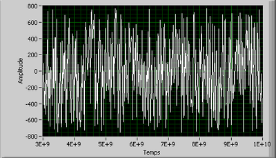
The screenshot I took a test result, where I intended to send MTA0, MLA7, DCL, OLA commands on the GPIB bus. Based on the screenshot, you kindly can let me know if the timings are correct, DAV, NRFD and NDAC, especially compared to the other?
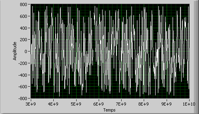
The diagram on the top 4 bytes sent via GPIB bus (40 h, 27 h, 14 h, 11 h). The diagram below is a zoom-in of the first byte (40 h). The vertical grid lines interval is 5 USD for the top chart, while 500 ns for the bottom.
Thanks a lot and best regards,
Hello WH Tan,.
I checked your captures and checked the commands that you send through the bus. The controller (the controller NAT9914?) with success all orders address and configuration of GPIB sends to the connected instruments. Orders through are MTA0, MLA7, DCL, and OLA.
Capture zoomed showed clearly that NRFD reported that the listener was ready for the data (by the listener), DAV then reported that the data on the bus is valid (by the talker) and the COMMITTEE reported that the listener has received data (by the listener). Because of the handshake, we can say that the listener has certainly received the data.
This configuration gives you problems? If the instrument at primary address 0 has data to send, the instrument main address 7 must be configured to receive these data after that MTA0 and MLA7 are sent.
I hope this helps.
Steven T.
Tags: NI Hardware
Similar Questions
-
NAT9914 - direct connection to the GPIB bus
Hello
I have some experience with NAT9914xx. I understand, from various sources, this ASIC is connected to the GPIB bus through a Transceiver ICs, i.e. it SN75ALS160 and SN75ALS162. While I'm waiting for the part, I wish I can perform some tests.
So here's the question: If the only devices exist on a GPIB bus is my test Board and a GPIB equipment, can I have the NAT9914 on my board test connected directly to the GPIB bus without using the transceivers?
Thanks & best regards,
Tan of WH
Hello
These transceivers are absolutely necessary to communicate with GPIB instruments. It's why they're in the hardware section of the manual 9914. Transceivers will display correct tension/line transitions. Without them, there will be errors in communication.
I hope this helps.
Steven T.
-
Send an e-mail greyhound bus schedule
I can't seem to "save under" file and send so it can be read easily
Windows vista basic
No, probably not. Pages such as these are generated 'on the fly' and sent in ways which do not lend their be copied easily because the data on them can change from moment to moment. Maybe send a screenshot instead.
-
Hello
New to the Commission, but have been using technologies of NI GPIB bus for five years in my business. I am currently underway to rewrite some DOS applications based on Windows so that we can support the later operating systems, but we still have a lot of existing code written. I have explored the possibility of using DosBox for some of these applications give a new life under Windows 7 and later operating systems. A particular application is a work horse very versatile app written and maintained by one of our application engineers.
Currently, I found that DosBox provides no support for the GPIB interface card. However, I downloaded the source to DosBox and found that it was written in Visual C++. Given my previous experience in porting applications for this platform, I am convinced that I could 'improve' DosBox to subsidize GPIB for DOS applications through a form of emulation. I think something in the sense of a DOS application running by calling the GPIB functions which are translated by DosBox in calls in the Windows of DosBox drivers.
Has anyone ever tried this before? I thought that the first step would be to understand (and maybe disassemble) the code contained in libraries of objects used by these programs (QBIB. OBJ, MCIB. OBJ, MCIBL. OBJ, etc.). I tried looking for sources for these but my research have developed dry. Has anyone been on this path and have had better luck? If this isn't the case, it would be possible to get more information on how the DOS driver strives to contribute to this effort?
Thanks in advance.
NOR-488. 2 v3.0 is now available for download:
For the version of NOR-488. 2 version 3.0: previous versions of NOR-488. 2 for Windows has not installed BACK and Win16 is supported on Windows 7 or Vista. It is now installed on all 32-bit versions of Windows. The feature is enabled by default, but can be disabled through measurement and Automation Explorer.
-
Hi all
I want to write a program for tempforce (temptronic), so that my program will control the tempforce as the compressor, head down, heat and cold.
Please help me to write the program its very urgent now.
Thank you.
First, find the manual. It should contain commands, you can send it via the GPIB bus. Those who learn. From there, he is to use some string manipulations to build these commands and with VISAS to send them.
-
Rearmament and automatic test of a controller (not the instruments attached to it!) GPIB card
We have a Council NI GPIB in an operation of great trial. Because reliability is absolutely crucial, I want to be able to force a reset of the GPIB controller card, but also run a set of diagnostic self-test on the Board of Directors. Note! I does not reset the instruments attached to the GPIB bus. I want to be able to reset the card controller itself and run automated tests on it.
I studied literature, but all I find are commands to reset instruments attached to the Commission.
Is there a test suit for the GPIB card and a way to reset?
-Carl Dreher
-
Workstation PC with full PCI (ie. 256) buses numbering?
Hello!
I have a problem with DELL Optiplex 7010 and two bodies SMU connected to it like this:
Port of PC PCie8372 1-3 metres of cable-> SMU - 8370 >-> the 1 SMU-1065 chassis
port 2-> 3 metres of cable-> SMU - 8370-> the 2 SMU-1075 chassis
Problem is that in Windows nipxirfk event log service complained that "PCI Host Bridge: bus Maximum number limit reached before listing all devices, status =-313563 '.
When I tried different things to solve the problem as withdrawal PCI GPIB bus and change SMU bodies on different ports on PCIe card, half of PC USB ports have stopped working and when I changed something the other half stops working

PC has limited the availability of bus numbers:
8< -="" -="" -="" -="" -="" -="" -="">
= Detection of resources OR root Bus utility =.
This utility determines the number of root PCI/PCI Express bus
devices on your system and if there is any number of bus
range limitations that could cause equipment problems.= SUMMARY =.
Bus single root detected.
Your system has a single root PCI bus.
Bus root has a limited scope.
The BIOS of your system has a limit on the number of bus range
You can assign to your PCI tree. In Windows XP, this limit is ignored
and has no effect. In Windows Vista and later versions, the limit is strictly
applied and cannot be exceeded. Thus, the amount of MXI-Express
You can reach the material is limited. Refer to the number of bus range
below the limits of your system.= DETAILS =.
-Root Bus: ACPI\PNP0A08\0 -.
Bus numbers range: [0, 3]
Status: Device is runningThis utility ran without error.
8< -="" -="" -="" -="" -="" -="" -="">
So I take is not enough PCI bus available on this PC to allocate sufficient resources for all connected devices. There is nothing BIO on bus PCI PC I could delete or nothing to what I could turn off, actually, I have to back PCI GPIB card and who will eat resources. The two bodies SMU are about half full of instruments and I need to add more than a few cards to one of them. PC BIOS is up to date. I was sort of the details with the support OR already, but they do not have solution. Our laboratory has two former HP/workstations DELL (is no longer available) with the limited numbering PCI bus that work with the same two bodies very well. I think that this problem is PC related BIOS and my computer is right on the limit of not working.
Basically, I need to know a few current PC workstation, used successfully to control at least two 2 SMU bodies. If you could check you workstation PCI bus numbering capacity with this tool EITHER:
http://digital.NI.com/public.nsf/allkb/BF84B75E08D2A7708625763B00670007?OpenDocument
And display the results here, I would be very grateful.
Jan,
Some Dell BIOS have an option to set the number PCIe bus max. A lower number allows more usable in a 32-bit operating system memory. I saw him in some positions as the T3600 precision work. On these machines, you access the BIOS and go to system Configurationoption"Configuration of the PCI Bus, and then change the value to something higher (such as 256). Can you check for this option?
-Robert
-
integer of 32 bits carried by gpib
Hello
I currently write software for the acquisition of data and control for a testing machine Instron with a GPIB Bus with Labview. The machine is not the youngest, so I cannot use the 488 commands, not the VISA controls. My control software works this far, but with the acquisition of data, I encountered some problems for which I couldn't find a solution that far. I just taught Labview to myself two months there, so sorry if my questions seem silly to you. I searched the forum and the internet and could not find an answer to them.
So here's my problem:
I like to read my Machine with the command "GPIB-read" data, it gives a string, so I gues it automatically assumes that the data are encoded in ASCII. Well, the machine uses its own coding, described in its manual! I read the header of the measure (it's '#I' in the ASCII format), after that there is a signed 32-bit integer that represents the length of my block of data. Then there is a 16-bit byte and after a lot of 32-bit signed bytes that represent my measurement data. There is no mark of separation.
When I got out, I just get a string of crazy ASCII code (outside the "#I" at the beginning)
My approach to decode the message, that is that:
Convert the ASCII code in binary code (not with Labview, I couldn't know how it works, either. there at - it an easy way to do this?), so I ignore the first 64 Bits (2x8Bits of the entire + 32 bits wide + 16-bit header) and then I try to divide the string into an array of 32 bytes long strings and see if the data is good. In my assessment, I had three values that when it is constant, it should be just three alternate values. I always get the wrong data and especially not, I work with Labview, but later I have to because I want to view the data in real time.
There is a lot of work and I just wanted to know, if I'm on the right track or if there is a simpler solution. Later, it shouldn't be a problem to display an array of integers as a wave, right? Is there any advice or you can give me any advice?
Sincerely,
Simon
- Request VISA 488. So I don't see why you can't use the VISA.
- A byte is 8 bits. There is therefore no such thing as a 16-bit byte. It's a Word.
- The string Unflatten is your friend here. You can use it to decode every part of your order. And since your actual data is just a string of 32-bit words, you can use the Unflatten of string to turn that into an array directly, just to make sure "Data includes table size" is set to false.

-
Streaming (record) data of Agilent 6674 interface GPIB-USB powered
Hello
I would like to save the output in more than 200 HZ to my power supply CC 6674 A Agilent with LabVIEW 8.2. Agilent 82357 A GPIB-USB interface is used to connect the power to the computer. And I used the instrument for Agilent 66XX driver I downloaded from OR.
For reading continuous data, I put the read.vi in a while loop and data saved by writing in the file lvm. (just for the starter, not a good sense, though) Please see the attachment.
The problem I have is that I can only save data in ~ 10 HZ then that what I need is at least 200 HZ.
It's my first time to the instrument control and I just had a little experience in the acquisition of data before. I had some confusion as below: no I have gained a point each time the while loop is executed? If so, I guess that the time for each loop (and therefore my data rate) depends on my operating system and the computer I have.
How many points will be acquired whenever the read.vi is run? That depends on the set 'count bytes' in vi or a single point anything? Are there other ways to get the data more efficiently? (want to write your own driver etc...) Any help would be much appreciated.
See you soon,.
Bohan
The rate at which you can run the VI is dependent on the instrument/GPIB bus and use of Scripture on a Measurment file. Yes, you get a voltage reading and a current reading with each iteration and the number of bytes read is so that you can get a complete reading.
I suggest you delete the entry in the file of the measurement of the loop to see how long takes of the instrument. That would be your maximum rate. If it's fast enough, use a different method to save the data. Architecture of producer/consumer if you pass the data to another loop via a queue would be a way.
-
Convert from 5.1 to 2012 to identify - gpib.vi
Hello
Could someone please convert the attached VI from Labview 5.1 to Labview 2012. I would greatly appreciate your help.
Source version: Labview 5.1
Target version: Labview 2012FYI: This Vi identifies all the devices connected to the GPIB bus, using the * IDN? or ID? query. Lists the identification for all instruments in response string. Provides a quick way to see what is there in the GPIB space, without leaving the LabVIEW application
Source: http://zone.ni.com/devzone/cda/epd/p/id/3759Thank you!
ShahPS, sorry for double post under labview subject, but I couldn't find a way to move or delete a post.
There is a Board for this http://forums.ni.com/t5/Version-Conversion/bd-p/VersionConversion where you will probably be helped quickly.
-
Writing a driver for the GPIB-ENET100 in C++ based on a Linux machine
I picked up some remains of a driver for this device and I'm trying to resurrect it for a new project.
Basic Comms between the host and the device of the GPIB-ENET work OK, I can analyze the GPIB bus for instruments and address address Analyzer connected properly.
But, if I try and write commands to the instrument I get an error GPIB.
Work of communication very well by using windows OR browser based tool, so I've captured the Ethernet traffic and found several types of messages I do not recognize. He also seems to be sending messages on port 5015, but also the main port 5000.
SO, my question: is there a document covering the interface with the device at a low level of TCP message? Alternatively, as I suspect it is the secret of stuff and I'm supposed to buy an expensive software of NOR?
SOLVED.
After connecting to the GPIB-ENET100 using ibfind and setting various options on board level it is essential to drop and reconnect the plug before attempting to connect and communicate at the peripheral level.
My version of ibfind opens a socket and my version of ibonl closes the socket when it is called to set a Board/device offline.
The driver now works perfectly.
-
Problem of earthing GPIB-USB-HS connecting to a laptop?
Hello
The installation guide for the GPIB-USB-HS asks to "ensure that the computer and the GPIB devices are at the same potential on the ground." I was wondering if there could be problems with the connection of portable computers (because they float)?
What should / could happen if the computer was at a different potential on the ground? A short circuit?
Where the potential of the Earth is different, the installation guide also mentions to use isolated a GPIB bus isolator/Expander or a USB hub. I guess that laptop USB ports are "isolated" and so should be good. Is this true?
Thank you!
Meister,
Because your laptop is "floating" it's referance (mass to the chassis) has nothing to do with your referance of material (Earth) unless you take measures to link the laptop chassis to earth potential. Attach a GPIB cable to your laptop and your equipment will provide a way to fulfil the potential difference between your laptop and chassis of the Earth through the GND signal on the Gbspecifications FOR bus. The GPIB bus is not intended to carry large currents (great potential of discharge) and you can force entry on the laptop protection circuits or equipment when you connect the GPIB cable. Its kind of like touching a doorknob one day dry after you walk on the carpet of wool - you will get a 'static' shock when make you initial contact. Do it at your equipment and laptop often enough and you will damage them.
A worst case is when the chassis of the laptop is linked to a different potential that the grounded equipment (usually due to strengthening of wiring errors). In this case there must be a current constant circulating in the commonly known GBIP GND signal ground loop. Noise and / or damage will be celebrated according to potintial unlike.
The cure is ALWAYS connect the chassis of the laptop on the chassis of the equipment by an external wire before connecting the GPIB Bus.
I hope that clarifies the reasoning of 'Warning' that you see in the installation guide. Kudos to you for reading your guide and to pay attention to the warnings! Never be afraid to ask when you don't understand warnings
-
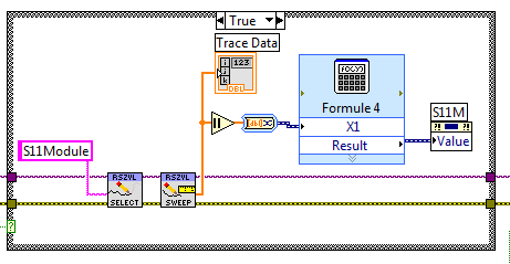
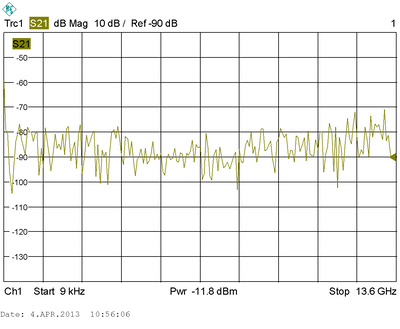
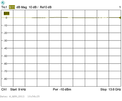
Problem getting a good graph of data
Hello, I am currently an intern and I need to create an interface in LabVIEW for a & Rohde Schwarz BALLS Network Analyzer.
The majority of the program working as it should, only retrieve the correct chart data seems to be a problem.
I get images on my screen, but the data does not match with the data on the device.
the device is connected to the computer using a GPIB bus, we use labview 2012 and labview 7 (program end must be in labview 7).
I think that the problem lies in the VI that retrieves data from the machine: (scan of rszvl)
explanation of the VI:
Here, I have 2 images of the Network Analyzer, these images are correct and the goal is to get these on my computer in labview. (the second is just a flat line)
Now, here's some of the creations I get in labview...
I've also attached the full VI
Should more information be required, please ask me
Thanks in advance,
Thomas V
-
Compare the previous values of a control?
Hello! I am communicating with via GPIB hardware. I'm rebuilding software to control the unit. Unfortunately, the GPIB bus is "clogged" with a lot of almost synchronous calls to the GPIB. In order to solve this problem, I would only request the GPIB, if a control on the front has been changed by the user. For example, to change a constant in time, the user changes the value in the control of constant front of time. An instant more later, a request is sent to display what unit was defined as the time constant. I wish that this request to the device will only be sent if the user has actually changed the value of a constant control of time. All calls are transmitted in time loop. Is there a simple and lightweight way to check if a control value has been changed? Thanks in advance for any help!
The structure of the event is your best friend here. Use a value for orders change event.
-
Error e/s of generic file using VI of the Keithley 2182 (v6) .llb
History, description of the system:
- Operating system: Windows 7
- LabVIEW version: 2012 SP1 (32-bit)
- Other materials: Nanovoltmeter Keithley 2182 A (via GPIB), controlled by these VI
The problem:
A few days ago, I could run the program indicated in the JPG file is perfectly fine. Now, I still get these errors of generic file i/o. I used to be able to safely output files, but now, the program is still stuck in the loop to try to get a measurement. I already looked at the problems of timing, hard drive space issues and problem of length of path names, but none of those who seem to be the problem. Between now and the time the program worked perfectly fine, no changes been made to the computer in addition to creating several files .txt for data.
I am at a loss to know what at the present time. If there is anything else that I could provide you think would help, let me know and I'll do it as soon as possible.
Thanks for reading!
Look at this a little closer error window. You will see that the GPIB i/o has been abandoned. This means that communication with the instrument has some questions. Here the common problems include 1) using a wrong address, 2) the instrument not configured to talk by GPIB or 3) the instrument is not hung the GPIB bus. First of all make sure that you can communicate with the instrument by MAX and troubleshoot from there.
Maybe you are looking for
-
Slate 7: how to get the new generation v1.05.7_user
I already posted a problem before ""slate 7: common and other: the text size too small". I have the version V1.05.6_user but on a slate 7 with build v1.05.7_user the problem does not exist == > How can I get the new version?
-
Hi all, I did managed to derive a CustomCursor of XYCursor at the point of being able to display an icon, or a label. I have also managed to create a CustomGraph derived from a diagram of dispersion and to specify the color of each point of the plot
-
Key slash or an exclamation mark before shows a t and T respectively
The slash or question mark on my laptop Pavilion g6 does not work properly. I have a 't' and 't' respectively It has nothing to do with the French keyboard. I can print [{}]} "\" |; :,. + | ------but not the slash or Question mark when I press the sh
-
original title: robocopy I'm trying to migrate data from a server to a new one with the file permissions of the files of users and records lost. So far, that's what I did, I used \\server1\share \\server2\share/sec /mir robocopy and robocopy \\server
-
Photosmart 5510: HP5510 prints less than 1/2 page black
About 1/2 at the bottom of the page, the black ink seems to run-out. He continues in blue or red, but then runs Altogether. It is the way that I expect to act if the cartridge vent was clogged, but they look clean. I tried the "Clean printhead" opti