Graphical evolution of positions programmability
Is there a way to change chart position based on a State of your VI? For example: I want to spend two charts based on a type of test. The cards are of different sizes. I know I can just wire the cards in my code, but what changes should I make labels and others? Are there property nodes to change the name of the maps?
As far as I know that the VI must be in edit mode to change the label name. You can use the nodes property to read and write the real position that your chart is currently and to set where you want it to be. This can occur during execution. If you want to programmatically change the names of the cards, you must have something like a second VI which runs and changes your main VI when it is closed and changes the names there by property nodes and other. It's a huge (but fun) pain.
You can even stack the cards on top of the other and just change that is visible (it's probably the best way to do what you describe). It is also something else you could do perhaps use an indicator of string to contain the name of your chart.
anyway I hope this helps!
Tags: NI Software
Similar Questions
-
Graphic customization DataTip position
Hello
I use Flex 3 stacked column property
I use two sets of columns
Passage of the mouse the column bars, the dataTip appears next to the bar.
I use a dataTip function to provide content for the DataTip & this may take 4-5 lines.
I wish I had the DataTip box always appear in the upper left corner of the chart.
So, I create a DataTip converter as shown below by moving the DataTip for x: 20 & y: 15
import flash.display. *;
import flash.display.Graphics;
import mx.charts.chartClasses.DataTip;
class /public extends DataTip MyDataTip
{
public void MyDataTip()
{
Super();
}
override protected function createChildren() (): void
{
super.createChildren ();
}
override the updateDisplayList(unscaledWidth:Number,_unscaledHeight:Number):void function
{
super.updateDisplayList (unscaledWidth, unscaledHeight);
this.x = 20;
This.y = 15;
}
}
I apply that to the table as (the event of creationComplete() of application):
myChart.setStyle("dataTipRenderer",MyDataTip);
But even when I do that, I get a flicker when I mouseOver the bar graph and the DataTip box appears near the bar, and then on the top left position
and when I mouseOver bars the display refresh problem takes place
How to override this so that the box always appear the top left corner flicker
-Sen
Since DataTip inherits from UIComponent, use the move method to position it. Also use the setActualSize method during the substitution.
super.updateDisplayList (unscaledWidth, unscaledHeight);
This.Move (20: 15);
this.setActualSize (unscaledWidth, unscaledHeight);
-
The graphic evolution of waveform details updated?
Hi all, hope everyone is having a wonderful July 4.
-Very well, so I'm new to labview and find my things around simple things well enough, but not having never taken an interest programming, Im a little behind in the logic of the machine, so I thought I would ask here.
EDIT: using labview 2009. Vision package
The research that I do is to analyze the electron Speckle Pattern Interferometry (ESPI) images and their fringes to observe weaknesses points/potential fracture in different materials and others. I made a simple VI which allows me to draw a line on the image the ESPI and exit of the intensity of the light to a waveform chart to make it easier to objectively determine the size of the area (area where the fracture is more likely to occur) plastic.
What I would like is to be able to draw or first set the coordinates of the line, then somehow, be able to move vertically - using just my mouse or a digital controller - and have the graphic waveform updated in real time, as I do.
Any suggestions? Ive attatched my programs, one called "line.vi" uses digital input to determine the coordinates of the line.
Also, since I did not sem to be able to set the bitmap images, Ive uploaded a sample of image here http://img594.imageshack.us/img594/3566/espiimage.png I don't know why imageshack converted into a PNG image if
Thank you all

Hi itschad,
have you read the context-sensitive help for the chart? Here we show what kind of data you connect to draw more than one line on the graph of some...
"Does a weird issue where once I select the line, the intensity profile keeps itself adding time and time again on the end of the table, so a table that could have initially 100 datapoints, stop of is longer and longer."
That's how cards work. They keep a story (that you disable constantly). You can set the size of the history buffer. If the default value of 1024 points, it's too much for you, you can cut it to 100 - it is just a right click away... Otherwise, you must use a graph as a graph plots only the points that are currently wired to him (it does not keep a history of previous values).
-
Graphical evolution Plot legend
I have no problem to change a legend of normal graphics plot with a property node, but I try to show three different sets of data on a graph. I tried to do a reference of the parcel with the legend of the plot and using the text of the legend. They should be definable when the VI is running, but the way that I tried to do, I had a reference error (1055 invalid reference). Defining the Plot legend or legend text would be acceptable if I could just understand.
I try to view 32 spectra, but only use 8 graphics and the name of this particular channel change. This without a the name of the channel FFT gets presented in the graph, but when I use the power of the spectrum VI I don't have the info from spectrum plugged into anything. So, I'm bringing my original table of channel name more and try to iterate to take the reference name and the correct pitch channel.
I only extracted the part of my code for this issue, so I hope it's easy to watch what I'm doing.
The first VI and Subvi are functional. The second Subvi is where I was trying to change the text of the legend. I tried other things too, but I just wanted to show a way I was trying to do.
I do not have the OAS add on so I can not check your main program. I looked at your sub vi and you do more code that you need. Take a look at my example, I put your 8 graphics in a cluster then used a table of references and tables for your index of chanel. Maybe this can give you some ideas for your program.
-
Graphical evolution of waveform changes during execution
Hello
I'm just started learning Labview graphical programming. It's so interesting that text-based programming.
The first issue is of course acquire analyze and display. But on the screen how to change the X axis and Y, scale of the axes during execution values.
Maybe you should b a little more clearly what kind of values you want to change. (range, offset, multiplier, etc..)
For example, to change the interval-y, yscale user property...... minimum or maximum range. The interval-x is a little more complicated, because you're dealing with a graph, when the x offset the changes automatically the history buffer is updated.
Of course you must also make sure to disable autoscaling, else it will be for the next update.
You can also change the formatting of the x axis. at the moment you show zero decimal digits. Also an axis 'style' with a few values more would be better.
-
Graphical evolution type at run time (by selecting the type of graph in drop dowm)
Hello
Currently I'm showing a chart bars. I want to have an option that the user can select the type of graph in a drop down. For example if he chooses the pie and pie chart is displayed. Is it selects the graphic line and graphic line is displayed. But I don't want to provide the button 'Edit' for the user.
No idea how I can make?
Thank you
Issa KhanHello
Use view selector
-
Want to read the size of a graphics window
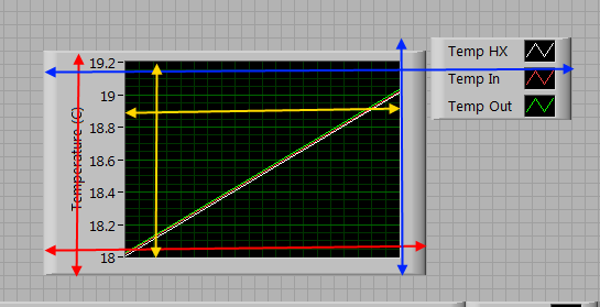
I would like to use the size of the graphics window to position the legend next to her, but cannot find the right property. "Bounds - width area" seem to include the entire control (blue arrows in the image below) included the legend, while 'Plot - region - size' seems to be that the area of the grid (yellow arrows). What I want to know is the size of the box which includes the plot and labels of axis (red arrows). Anyone knows what are the properties would get me this information?
Way is the simplest steps.
1 set the visible property of the legend to false.
2 get the limits
3. set the caption to the visible and move as you want.
-
SignalExpress-Sweep type configuration problems
Hello
I am creating an analog signal with a sweep to make the change in the frequency of my signal.
I chose "Sine wave" as a type of signal.
Then, configuration of the scan, I have a problem.
Indeed, the type of configuration, I have chosen is "exponential" (so that the frequency varies from exponentialy). But the graph on the right side of the window as if I had chosen linear.
When I'm runing the VI, does the frequency varies from exponentialy but the graph remains as if it were varying linearly.
Is this a bug?
Is anyway to remedy?
Thank you very much for your answers.
Hello
This is the normal behavior.
If you take a look whenever you change between exponential and linear from the point to the graphic evolution. For example, if 1 k to the exponential value, the value of iteration is 400, Linear 1 k the value of iteration is completely different. In fact, this graph does not show you values like a curve, because when you assign exponential the y-axis becomes exponential, so the graphic scale variations becomes exponential but not the curve.
Please let me know if you have any doubt.
Thank you.
Best regards.
-
Angular velocity using the entrance of counter BNC-2120
Hello
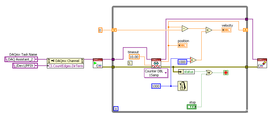
I'm trying to measure the angular speed of the motor shaft with an angular encoder connected to counter input BNC-2120.
I found this file vi in the forum in a discussion by Macdonald and duy.
I'm doing the same... and I'm in the form of data values. but please can someone help me because I do not understand what degree or radians data of position and speed too if it is in rad/sec or deg / s etc...
the iam encoder using 3600 gives impulses /revolution. Is it possible to graphically display the position / data speed while the vi are running.
Kind regards
ruser.
Hello Fesmi,
No change is required for the counter 0/connections to your encoder. You will use 1 meter unit NOR as the sample clock Source i.e./DeviceName/Ctr1InternalOutput. Version of LabVIEW 8.5 of the example has been attached.
Kind regards
M Ali
Technical sales engineer
National Instruments
-
Hello! Invite please, if you can programmatically create compliance fumes graphic value 3D (Position - value) pairs.
Or probably do that manually through 3D graphics properties?
-
cannot complete the assessment.
My computer uses 1 GB of RAM and I have added a new RAM, instead of 1 GB, I added 2 GB of RAM
and then I tried to update the speed of my computer... but failed...!
I said that I should reinstall windows... and I did... but the old problem still appears. !
179354 (1460) - winsat\processresults.cpp:0672: available for the operating system total physical mem: 1.99 GB (2,146,172,928 bytes)
179369 (1460) - winsat\processresults.cpp:0861: not limiting DWM Score 1.0 - no DX9 capeability
179369 (1460) - winsat\processresults.cpp:0965: capeability No. DX9 - limiting D3D Score 1.0
179541 (1460) - mlib\syspowertools.cpp:0904 >: 381b4222-f694-41f0-9685-ff5bb260df2e value of the power system active"Instakll the correct graphics driver.
"A programmer is just a tool that converts the caffeine in code" Deputy CLIP - http://www.winvistaside.de/ -
720 x 480 source - customer needs 1920 x 1080 H.264 files?
I have some pictures of 720 x 480 to SD I need to make a file H.264 of 1920 x 1080 for a sign of digital video. I have 14 seconds, so my idea was to use a few clips from 720 x 480 images on a canvas of 1920 x 1080. This way my images won't get blown out and I can squeeze more visuals on the screen at the same time.
What is the best workflow to achieve? Start with a 1920 x 1080 project file? Create a sequence of 1920 x 1080 within a project of SD? Any ideas would be appreciated. Thank you!
Yes, you can certainly do what you do. You may need to select a pre-defined sequence that closely resembles your terms of delivery (you don't mention the cadence of your images or your delivery file), and then click the settings tab in the dialog box new sequence and affecting editing custom Mode. In this way, you can easily change all settings that do not match your delivery needs. A square of 1920 x 1080 pixels to your required pace sequence should be enough.
One thing to note is that there is no specific "project" setting - in Premiere Pro, a project is simply a sequence container, so you can have several sequences with all kinds of different combinations of parameters.
Anyway, once you have your sequence established (you could save a "Preset" if it's something you do once again), you can plop in your images/graphics/etc. and position them where they should be. I do similar things for digital signage, it is entirely feasible.
-
Distance of the camera setting
Hello guys...
I want to do my job, but I have some problems here...
I put my first point the camera of interest to-93.4513 (you can see the picture below) and my first position of the camera at the - 675.2695

and my second point the camera of interest 23.3628 and my second camera position - 558.4553

so I want my object is zooming slowly. But what I got here, when I played it back, this camera zooming up more and he zoomed out to the second position of the camera. You can see the image below that point of interest and position values are increasing and decreasing.

I use AE CS5 for mac. I don't have this problem when I'm with AE CS3 if I'm not mistake...
I would be the spatial interpolation is defined on Bézier. Here's what I'd do. Take a look at a top view with the camera so that you can see the trajectory. Now, press the G button to set up the pen tool or click on the pen tool until you reveal the convert vertex tool. It looks like a V on the side.
Now, click on the image in your comp window key intermediary. You can not convert the keyframe in the timeline panel, do it in the comp window. It converts the keyframe in linear. That should do it.
I would like to know if it was the problem of a sudden course if I could see the editor of graphics with the position and the speed values. I bet it looks like this:

You could also solve your problem by selecting all position of the keyframes and change the Interpolation of linear keyframes. You'll find it under Animation > keyframe Interpolation. This allows you to convert all the keyframes to linear, which will probably be OK for this problem, but it can clog up to other more complex movements.
-
Graphic property node indicator position
Hello! I have several graphic indicators and I want them to appear on certain positions, so I created property nodes where I define their exact position. I have a tab control in my design to separate the 2 pages front and the problem is that indicators are displayed on both pages. I want them to appear only on one page, how do I solve this problem?
Thank you for your time.
Hi cocopa.
On the front panel, if you drag the graphical indicator in the appropriate page then it should stay there. If the graphical indicator has a shadow, it is on the top of the tab rather than inside a page control. In the block diagram, you must have a business controlled by the tab control structure. When you want to adjust the graphic position, have the indicator and the property node in the box to the right page. That should allow you to move the chart inside your tab control page.
Kind regards
Daniel H.
-
Using the XY Positions of the graphic intensity sliders
Hey all,.
I have an application that displays a graph of the intensity. I have two sliders on the chart that I use to make a box around parts of it to "zoom in". Right now, I manually type in the positions X and Y of two sliders in the areas of digital control, for use on the rear panel. Is it possible to use numbers without enter them into digital orders every time?
Thank you
LANL13
You almost her, simply use the ActCrsr property to set the active cursor before reading the values. Exploited property nodes sequentially up and down then write the value of ActCrsr on top, then pull down, then add the properties of cursor position.
Standard workflow you get used to using the properties with graphics. Set the cursor assets/plot then read/write of interest properties, often this is done in a loop For.


Maybe you are looking for
-
SategoX200 - 21(d): where can I download the recovery DVDs
Hello Anyone know where I can download the recovery for a 200 - 21 d Satego X DVDs. I have a buyed from the Germany, so everything is in German :-(. Thank you
-
Error retrieving my hp dv6-6080
HI. Today I wanted to reset factory my dv6-6080 to factory setting by using disks.it copied to hard drive recovery disks and then it restarts to continue the game up.after it starts he can't go on and show this error:Error! : rm has detected an error
-
Read power meter in LabVIEW via RS-232/RS-485
Hello! I have a power meter, an advanced WM14 DIN power Analyzer. I want to display different values, Kwh, WILL, etc. Kvar, the meter in the graphs in labview. I have just a basic knowledge of Modbus RTU and with RS-232 connection. But I don't know h
-
5 suspect in Drive_verifier_iomanager_violation clean, stable hidclass.sys Wacom Intuous install
Hello ~ He spent the last three days, trying to understand why I get this particular bsod. I learned more than I have in the last 4 days on the resolution I have in the last 5 years... I could not trying to understand that me self... so now I'm going
-
Hei. Why ma jeg opp Creativ-Cloud sealing gang jeg Starter Macen ny laste?
Hei. Why ma jeg opp Creativ-Cloud sealing gang jeg Starter Macen ny laste?