How output waveform desired by USB 6251?
Hi all
1 I have problem like this: now, I use Laview 7.1, NI USB-6251, I want to output with desired waveform (shown on the attached picture). I want to know: 6251 USB can perform this problem. If Yes, can you advice me to solve it, I'm most recent with Labview.
Waveform details: start I want to output current train of pulses with the decrease in the amplitude, until the amplitude of the current touch 0, after that USB-6251 output current with waveform of Sawtooth (but flat at the top sawtooths).
Waveform of power like this:

2 I want to know: what the higher frequency and the amplitude of the pules (or / and sawtooth) which can produce the 6251 USB?
Can you show me how to download files, and Image to my message? I wat to download the *.vi file and the image of waveform of the current as I write.
Thanks in advance for any help!
CUONG. NM
Hi Cuong,
The modules of the series C, such as the NOR-9265, can be used in a chassis for CompactDAQ 9172 - OR . This chassis is connected to the computer via USB, and contains 8 slots for modules of the C series as you want. My recommendation for the type of installation you need would be to get an analog inputs NI 9205 module, but also a module e/s digital NI 9401 for use in the cDAQ-9172. For a complete list of the C Series module and the description of each, please see titled knowledge base "supported C Series Modules in the cDAQ-9172 CompactDAQ OR.
"" Using the NOR-9265, you will be able to use similar example DAQmx programs to accomplish your task, and these examples can be found in the Finder example under input and output material"DAQmx" analog generation ' current. Unfortunately, these three devices mentioned in my last post are currently the only options available for the current production and the cDAQ chassis is the only USB solution. Hope this helps also,
Tags: NI Hardware
Similar Questions
-
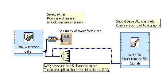
I did separate VI for reading signals from several channels on a map of NI USB-6251. I would like to combine these in a VI VI alone so that they can run that at the same time, however, there is an error if there is more that a single DAQ Assistant in the same--> error-50103 VI was held at DAQmx controls Task.vi:32 (the specified resource is reserved. The operation could not be performed as indicated.)
All the inputs of channel must then be read in with a single DAQ Assistant, but all of the data on different channels are not separated. Can save this data in a matrix or otherwise manageable which allow to facilitate the analysis of the data from the separate channel entries?
I tried to view the data in a file of measures, but then when I tried InPort data, I could all the data I wanted.
Hi AggieGirl,
Good afternoon and I hope that your well today.
First of all, you will not be able to have more than one DAQ Assistant by input analog or analog output task because the device has only one of each. So, you must have a DAQ task to HAVE and AO. (This is not the case for DIO static).
There is far from split signals using the express VI - signal splitter.
When you say you saved this file and it does not work, how it did not work? The Express VI - save a file of measures needed to manage multiple waveforms. Can send you your code & explain more about what was not OK on the file?
Thank you
-
How to sync 3-way with USB-6251
Hi all
I have a NI USB 6251, Labview8.5.
My system includes: + a waveform output stimulating (I use Dev1/AO1 or Dev1 / AO0)
+ Two channels for (I use Dev1/ai0 and Dev1/ai1) acquisition of input signals.
I modified example "Multi-multifunction-Synch I-AO" Find example\Hardware entry and Output\DAQmx\Synchronization\Multi multi-function.
I added a single channel for this example and I want to 3 channels at the same time working, but during process occurs "error-50103 occurred at Task.vi:1 DAQmx Start" or the possible reasons: the specified resource is reserved. The operation could not be performed as indicated.
I have taken a long time, but can not solve this problem.
Can you give me any advice.
Thanks in advance for any help!
MC
As the specifications clearly indicate, your Board does not support simultaneous sampling. There is a simple element A/D and all channels are multiplexed for her. When you select several channels, the first string in the list will be sampled, then the second, etc. There will be a time that you can determine and it is very small, but it will always be there. If you need simultaneous sampling of the value true , you can buy a DAQ card that supports.
-
How to reduce the noise in an acquisition of data USB-6251
Hello world!!!
I have a few questions about a system that I have developed using a data acquisition OR usb card 6251. The pressure control system.
First of all, the signals are acquired using an Omegadyne pressure transducer. (Typically, the signals are between 0.1 mV and 38 mV, pressure is between 0 to 50 lb/PO2). The transducer is connected to the usb-6251 daq card (I use pinout of the 1 and 2 for the signal acquisition, also, I have a 100 K resistor between pin 2 and 3) and the card is connected directly to the computer. In addition, I have an omega counter, I use it only to see pressure on the screen. But long term, it will be useless.
One of the problems I have found is the noise, the measured voltage values change much. Even if the figures in the player screen do not change so much... (or do not change)
The system should regulate the pressure so if every second it changes a lot, the system did not work properly. How can I make the technical more similar to that of the meter? In the labview program that I use, I use a block 'base DC', he reduced noisy signals a lot, but not enough that experience, I need more stable values.Thank you
I don't mean in the /manuals of broaching and do not open .doc from unknown sources files (a chart single .png is fine ;-))
However, I guess you already measured in differential mode and the 100 k is a path for the currents of polarization forever
The reason why your counter is stable can be the fact, that she has a generation to filter low pass (on average) with a big enough constant time.
First things to do:
You did it that there is a filter anti-aliasing suitable for your sampling rate?
Read the signal on at least 100 ms (120ms in line 60 Hz) possible higher sampling rate and take a look at the signal (and display a chart as a .png or .jpg image)
This will give you an idea how the signal looks the same. Then you can choose a filter according to your system and the signal or other investigations to do not even catch the noise (groundloops, protection...)
You can use an example on the screws or the testpanel to the MAX for this measure. (Personally, I prefer a similar scope :-))
-
How I choose the USB-6251 (full speed or high speed) data transfer rate?
Hi, this is bose, FAE Samsung in Korea.
I saw the USB-6251 specifications that it transfer data at high speed or full speed.
How can I select speed mode?
It depends on computer?
Thank you.
Fairly certain, it is totally dependent on the USB hub.
-
How properly using USB 6251 to measure the DC voltage
Hi all
I have a problem as in the http://forums.ni.com/ni/board/message?board.id=170&message.id=404676&query.id=250408section.
I'm sorry for the repetition of the subject, but I read all your advice and have not yet solved the problem.
My task very simply: I use USB-6251, differential mode to measure battery voltage Energizer 1.5V. But result shows > 10V? Mean.VI shows greater 4V (see attached photo)
I do not understand what happed with my task?
Please help me!
Thank you very much!
MC
Hello
Please post on the Forums OR!
How do you have your battery connected? Do you use polarization resistors? This could be a grounding problem and can be fixed if the polarization resistors are used. See table 1 in this document , and the differential configuration for a floating source.
-
How to properly connect USB-6251 to measure the DC voltage
Hi all
I have a problem as in the http://forums.ni.com/ni/board/message?board.id=170&message.id=404676&query.id=250408section.
I'm sorry for the repetition of the subject, but I read all your advice and have not yet solved the problem.
My task very simply: I use USB-6251, differential mode to measure the voltage of the battery (Energizer) 1, 5V (I connect AI0 pole positive and AI8 to the negative pole). But result shows > 10V and Mean.vi shows greater 4V (see attached photo).
I do not understand what happed with my task?
Please help me!
Thank you very much!
MC
You have a floating signal source. Have you connected resistances to remove polarisation currents? Look at Table 1 at this link and make sure that you connect the wires in this way:
Wiring and considerations of noise for analog signals
You mention that you use differential channel AI0 again I can see that you measure AI4 on your façade. Have you tested the Max connection? Are what kind of reading you there? Don't forget to select the continuous Acquisition and acquire 100 samples to 1000 Hz. display a snapshot of the reading you get there.
-
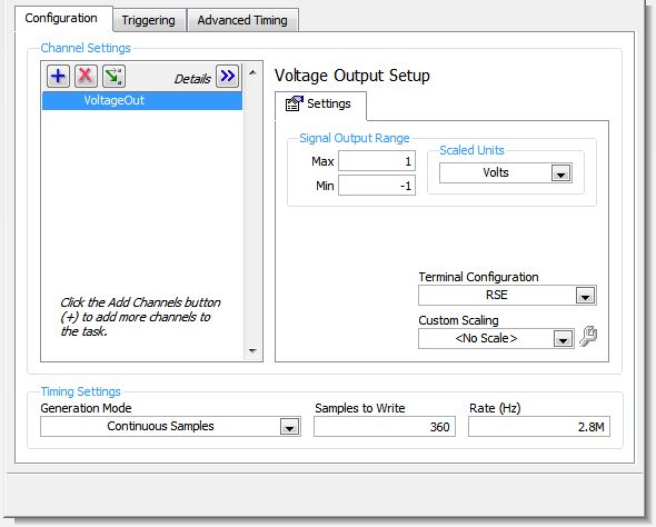
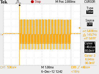
I use a box NI USB-6251 and frequency max I can carry out to an0 an1 is 8 kHz using the following parameters. Is there a way to reach a frequency higher on the analog output ports?
Config:
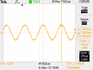
Capture of the oscilloscope:
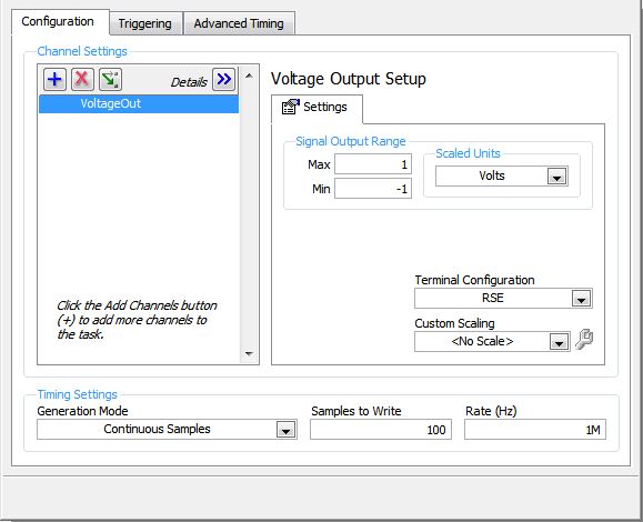
I've reconfigured the config to try and hit 10 kHz and captured the following response.
config:
Oscilloscope Capture: (before port analog flat doubled)
The signal is emitted for 7ms then faints.
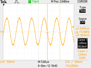
Any ideas how to set up the analog interface for a sine wave of 100 kHz to the stable address? I could only create a stable 8 kHz wave.
To use higher frequencies, you'll need to use LabVIEW or custom code. I used the example of "ContGen - IntClk.c" located in "C:\Users\Public\Documents\National Instruments\NI - DAQ\Examples\DAQmx C\Analog Out\Generate Voltage\Cont Gen Volt Wfm - Int Clk ANSI" and changed the two lines of code to achieve higher frequencies.
2 changed lines:
 1. data[i]=1*sin((double)i*2.0*PI/25.0);

 2. DAQmxErrChk (DAQmxCfgSampClkTiming(taskHandle,"",2800000.0,DAQmx_Val_Rising,DAQmx_Val_ContSamps,1000));
Output waveform:
Thank you TO help me with this. =)
-
NI USB-6251 - Signal Express - Input Ports display signals idential
Hello
I plugged a DET50B (phototedector) at the port of entry Ai0 in my case NI USB-6251 and thanks to LabView SingalExpress 3.0.0 took a look at the Ai0 signals and Ai1 by clicking on the following points:
Acquisition of Signal-> DAQmx acquire-> analog input-> voltage
I was expecting the Ai1 signal or 0 Volt, because there is nothing connected to it and the Ai0 signal vary in what concerns the light I was shinning on the photodetector. Instead, the Ai0 amplitudes both Ai1 were identical and corresponded to the light I'm shinning.
How is it that these ports appear to be connected? It's the same thing when I opened other ports for viewing by SignalExpress except the Ai8; This one seemed to be at zero (probably because he does not physically exist on the NI USB 6251 which Ai0 - Ai7).
No, you will not read 0 Volts to a channel not connected. Do a search for 'ghosts' for a detailed explanation. If you want 0 voltas on a channel, you need to gnd.
p.s. You do not have a signal generator Board. New questions should be mailed to multifunction DAQ and Signal Express cards
-
Filter low pass analog (anti-aliasing filter) external to the NI USB 6251 housing
Hello everyone!
-I m trying to acquire an analog signal of tension (high frequency content) using a connected to an edge NI USB-6251 BNC-2110. I learned in this Labview Forum that NI USB-6251 has no analog low-pass filter programmable (or anti-aliasing filter), so that I can't help but jitter when scanning my signals. For my application, the cutoff frequency of the analog low-pass filter must be equal to 100 kHz or MORE (maximum of 500 kHz). A possible solution to solve my problem, would be to work with an external analog low-pass filter before you scan the voltage signal. Based on this I'd like to know:
(1) national Instruments develops analog external filters? I need a filter which also has one output, analog, so that I could send also the low-pass analog filter filtered signal to my NI USB-6251 box to scan correctly it!
(2) what model of external low pass filter would be compatible with the NI USB-6251 housing?
Any help would be much appreciated!
Best regards!
Hello
all high resolution of the M series (628 x) cards are equipped with a filter low pass which can be enabled or disabled programmatically. For the anti-aliasing filter feature, examine the boards of National Instruments DSA (dynamic signals Acquisition) acoustic and vibration measurement
currently the NOR 9221, 9225, 9227, 9229, 9233, 9234, 9235, 9236, 9239 and 9237 C Series modules feature anti-aliasing filters. These modules are intended for the high accuracy measures for which anti-aliasing filters are a necessity.Houssam Kassri
OR Germany
-
Not recognized USB-6251 (detected) to the MAX but is detected by the Windows 7 Device Manager
Does anyone have a solution to our problem?
USB-6251 is not recognized (detected) in MAX but is detected by the Windows 7 Device Manager.
Is our configuration: Windows 7 (64-BIT), DAXmx 9.3.0f2, MAX 4,8 and USB-6251 (S/N 12B647A. P/N 194929 D - 04 L)
We had a 'ready' indication/led the 6251.
We tried several things... (all do not work)
1. we have installed DAQmx 9.3 (for Windows 7)
2. clean MAX Database by the following
http://digital.NI.com/public.nsf/WebSearch/86256F0E001DA9FF86256FFD005B827C?OpenDocument
Michael B.
Yes the 6251 appears as a DAQ hardware. Device charger OR placed in the auto-start services window. We have refreshed MAX.
Success! I had to manually start the device loader. Even if the service has been set to autostart, it did not work. Right-click on the service shows that the beginning was selectable. Click Start and the service began. Start to MAX and can now see the device. Open the front panel.
How does the monitor devices OR running in the interface of the status bar to the device loader service?
I don't understand why the service was not working. Is it a security issue? I am logged in as administrator. I'll try once again as a normal user.
-
Tilt on a random channel USB-6251
Hello everyone
I hope that you will be able to help me with this problem that haunts me more than two years now.
I use a USB-6251 box to acquire 3-way @100kS/s (acquisition of sample of N, N ~ 250 ksps), while simultaneously sending a result to one of the analog channels.
In my application, the period of channel inter is very critical, that is, it must be precisely known (but not necessarily zero, although it would be nice).
Not convinced by the results mediocre I got, I decided to perform a simple test to measure the impulse response (one so distort the channel) between the AO and the first 4 boards of my 6251. To avoid ghosting and keep the 4 AIs isolated from each other, I plugged 4 amplifiers contained in a TL084 IC in follower of voltage configuration to AIs, while feeding their entries with the AO signal outputs.
I sent a Twitter and is its correlation with the acquired signals. The chirp was generating an impulse response "low pass filtered", in order to better appreciate the delays of the fractions of samples in the impulse response (IR).
Some very confusing results: the IRs are randomly (by comparing the various acquisitions) place in the "t = 0" and "t = 1", very rarely to 0.<><1, while="" i="" was="" expecting="" to="" see="" 4="" irs="" "equi-spaced"="" within="" 1="" sample,="" since="" the="" 6251="" contains="" a="" single,="" multiplexed,="">
The same random behavior can be observed by sending a simple sinusoidal signal and by checking that the 4 acquired signals are randomly out of step with the other by exactly 1 sample.
I repeated the same tests in Matlab (using data acquisition and directly call the library daqmx) and Labview 8.2, still getting the same resut. I also tried (in Matlab) only change the sampling rate (as low as 8kS/s) and the number of samples acquired, without any significant change in the results.
So finally, my question is: is there some kind of post processing going on behind the scenes which aims to align the entries, that fails somehow? Or is it because of some bad attitude? Would it be because of lack of samples?
Has anyone else had similar problems with Renault multiplexed?
Any thoughts on this would be highly appreciated
Kind regards
Giovanni
-
NEITHER USB-6251 antialiasing filters
Hello
NI USB-6251 and I have to use the maximum sampling frequency 1250 Khz how I could put anti-aliasing filters? help please
I have also the NI 9234 to receive a signal of the 4 channels at sampling rate 50 khz for each channel should I put anti-aliasing filters in this case or not?
Thank youThe USB-6251 casing served only at this rate on a single channel. If you use several channels the total maximum rate is 1 MECH. / s. You must install an anti-aliasing filter before entering the device. Filter bandwidth could be as low as 625 kHz (Nyquist frequency) or a little more depending on the noise or interference that accompanies your signal.
The NI 9234 is a built-in anti-aliasing filter. Your sampling rate is slightly less than the maximum sampling rate, you should not have any other filter. If you have an extreme case of a strong interference signal just outside the bandwidth of the signal, a special filter could be useful
Lynn
-
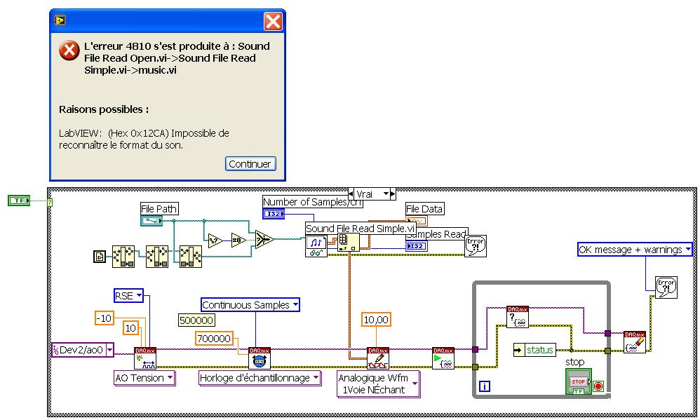
Read wma file music by AO card usb-6251
Hey everybody,
Can I play music wma file throught analog output or usb 6251. I have an error that my program "can not recognize the sound format. I am user of the version of Labview 8.5.
If someone knew and can help me, please.
Marek
Your wma file type. LabVIEW can read wav files only. But you can find many free software that can convert your file to wav format. However, it is a little big to 15 MB wav format
-
ACQUISITION OF DATA NOR USB-6251
is it possible for the box USB-6251 to provide an output for a test set-up during playback of the inputs of the device even? for example: 10VAC Ridge to Ridge on the luminaire, mixed the sine and square wave signals of the luminaire to the data acquisition Toolbox.
Yes. The 6251 has two outputs analog and 16 analog inputs. Open finder example and looking for examples of both. Under input and output hardware > DAQmx > Syncronization > multifunctional, it is an example of analog inputs/outputs synched.

Maybe you are looking for
-
Additional monitor on 5 k iMac
I soon in the market for a new Mac and considering the iMac of 5K, well who wouldn't? I currently have a Mac Pro (early 2008) and two Cinema Display 20 "with DVI connectors, which are always excellent and I love them. I would use at least one on them
-
DV7-1211ea: cannot download DV7 Windows 7 drivers
Machine of my son started showing all kinds of errors, the worst was the Nvidia graphics drivers kept crashing. After looking at the machine, I found a miriad of errors to the file and that the player has been occasionally clicking on I decided the
-
My system is: Windows Vista Edition Home Premium 32 bit Intel Core 2 Duo T7100 CPU 2.00 GB RAM Help, please!
-
How can I order the printers in a printing pool?
I have 2 computers and 2 printers EPSON identicall and I want to create a pool of printing on each computer to achieve the following: Computer 1 prints on the printer 1 and uses only the printer 2 as a backup in case the printer 1 fails. Computer 2 p
-
I'm crazy. Someone help me. I have three papers to write and 3 exams to take.