Filter low pass analog (anti-aliasing filter) external to the NI USB 6251 housing
Hello everyone!
-I m trying to acquire an analog signal of tension (high frequency content) using a connected to an edge NI USB-6251 BNC-2110. I learned in this Labview Forum that NI USB-6251 has no analog low-pass filter programmable (or anti-aliasing filter), so that I can't help but jitter when scanning my signals. For my application, the cutoff frequency of the analog low-pass filter must be equal to 100 kHz or MORE (maximum of 500 kHz). A possible solution to solve my problem, would be to work with an external analog low-pass filter before you scan the voltage signal. Based on this I'd like to know:
(1) national Instruments develops analog external filters? I need a filter which also has one output, analog, so that I could send also the low-pass analog filter filtered signal to my NI USB-6251 box to scan correctly it!
(2) what model of external low pass filter would be compatible with the NI USB-6251 housing?
Any help would be much appreciated!
Best regards!
Hello
all high resolution of the M series (628 x) cards are equipped with a filter low pass which can be enabled or disabled programmatically. For the anti-aliasing filter feature, examine the boards of National Instruments DSA (dynamic signals Acquisition) acoustic and vibration measurement
currently the NOR 9221, 9225, 9227, 9229, 9233, 9234, 9235, 9236, 9239 and 9237 C Series modules feature anti-aliasing filters. These modules are intended for the high accuracy measures for which anti-aliasing filters are a necessity.
Houssam Kassri
OR Germany
Tags: NI Hardware
Similar Questions
-
How to set the low-pass analog input (smoothing) on my DAQ configuration filter?
I read the following of the PXI-6251 manaual:
"On some devices, the cut-off is fixed. On other devices, this filter is programmable and can be switched to a lower frequency. For example, the hardware OR of the 628 x have a programmable filter with a cutoff frequency of 40 kHz that can be activated. »
It does not explain how you know this value. So, I have the following questions:
1. How will I know what the cutoff freq is on my device?
2. How do I know if its programmable?
3. how this program if it is programmable?
I use the PXI-6251 in conjunction with the PXI-1031.
Thank you very much.
The PXI-6251 has no anti-aliasing/programmable filter. Bandwidth (-3 dB) small signal from the 6251 is 1.7 MHz.You will find these information in the specifications manual.
If you need a filter, you must add the signal conditioning yourself.
The 628 x M high precision tips are the only cards of the series M 'programmable' low pass filter. Check this KB for more details.
I hope this helps.
Luca
-
Pass an argument of jsx external to the html Panel?
Hello world
Can you please tell me if it is possible, somehow, to listen to the event of jsx externally in html Panel? What I'm trying to do is to move a JSX argument to the HTML Panel and update
the Panel with her.
Thank you very much
Sergey
Hello Sergey!
What I was suggesting private to you (I report it here for the sake of others) is to use the technology of CEP5 as soon-to-be-released: http://blogs.adobe.com/cssdk/2014/04/introducing-cep-5.html
Especially, the part that says:
Call of ExtendScript in HTML DOM: most Adobe applications currently supported (including but not only CC of Photoshop and Illustrator CC) will include a new ExternalObject that provides an API that allows developers to send ExtendScript events in JavaScript/HTML5
But we must wait for the next update of the CC apps to support!
Concerning
Davide Barranca
---
www.davidebarranca.com
www.cs-extensions.com
-
Example of signals with a filter anti-aliasing
I use PCI-6259 6221 PCI and USB 6221 cards in different configurations. As I understand it, is that the anti-aliasing filter on all of these cards is fixed to pass to the frequencies of 1 MHz. If I'm a signal from a RG58U BNC cable that is supposed to contain higher frequency of 1 kHz sampling, but there is noise of high frequency present there. A sampling of the signal to 2 kHz would be enough to acquire the signal correctly, or these high frequencies would affect the components of low frequency on sampling?
I read about too much sampling that allows you to use digital filters (I'm guessing that software filter can be used) If you sample the data at a higher rate. You should always use the anti-aliasing filter, but the required parameters are more relaxed. Would this work in my case? The anti-aliasing filter on my cards has a very high bandwidth, so I don't know how much I need to do to acquire the signal correctly oversampling. Is there an equation?
Also, if the analog inputs for data acquisition cards are generated by a filter (for example when recording ECG or EEG) which allows you to specify a bandwidth frequency, I still need a filter anti-aliasing? Would be the distance between the amplifier and the DAQ card much a difference when it comes to the generation of noise on the cable?
In general, I try just to see if my current collection method at the rate of Nyquish with the maps I have is good or not. I just save the data without even using any digital filtering (software).
That's right - if you go down to 10kS/s then the temporal resolution and minimum pulse detection would 100us. If it is a just sampling rate or not depends on your requirements for the accuracy of timing and jitter. In other words, if it's OK that your pulse Detection could could delay until 100us then a 10kS/s sampling frequency should be OK.
-
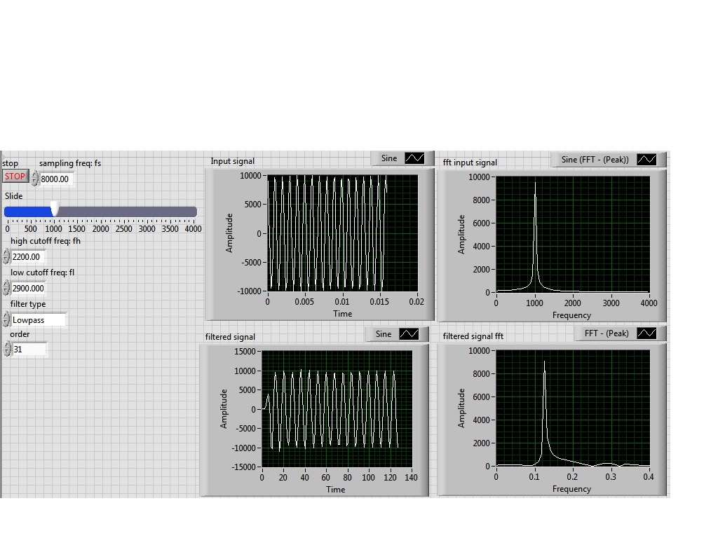
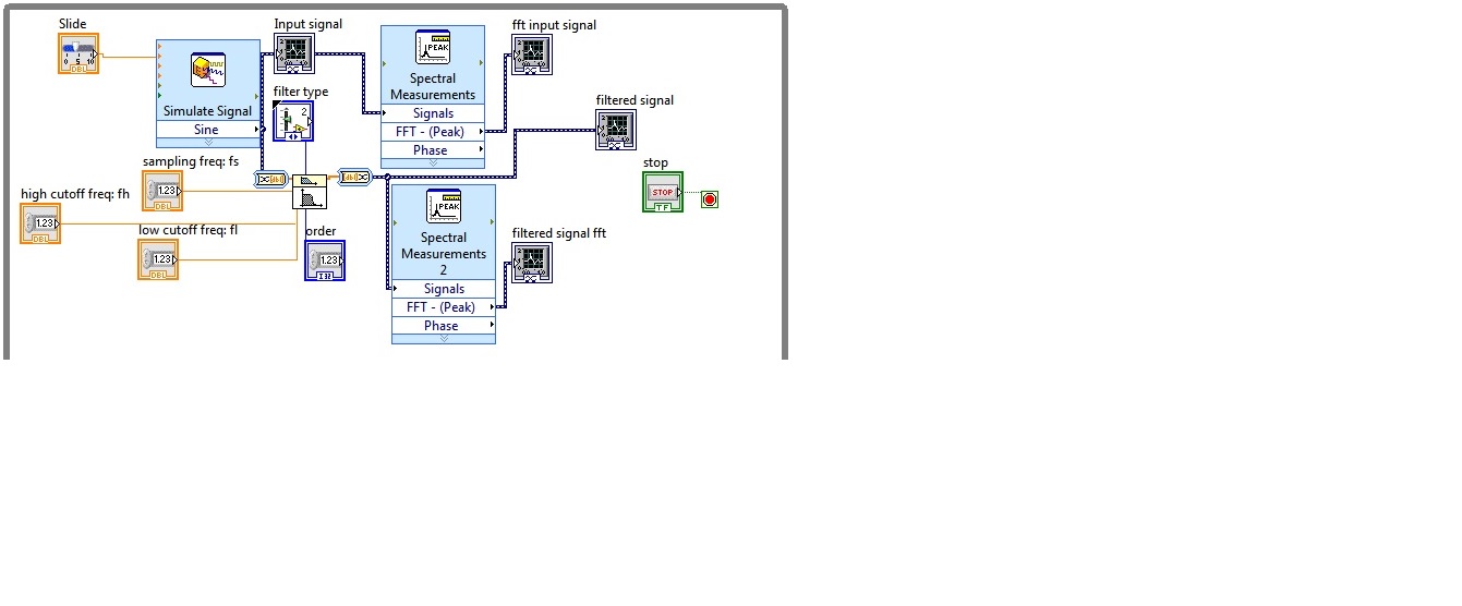
I'm simulating a sine wave at approximately 1000 Hz (I'm variable according to the frequency with a slider), I would like to pass this signal by a lowpass filter (butterworth) with a high frequency of 2200 Hz cuttoff and a low pass to 2900 Hz frequency. However, the output after the filter frequency seems to be lower in the order of a thousand. the output frequency is about 0.1 Hz.
Y at - it someone who can guide me please to solve this problem, I tried different filters and I'm still having this problem, it would be incorrect sampling?
I enclose the block diagram and the front panel
Because you use express screws and the type of dynamic data...
You convert the signal of DDT (which contains the clock information) in a table DBL to perform filtering. Take it a DBL array (which contains no data of timing) and converted it into a DDT (which now contains no data timing). That's why when you try to view and analyze it you have lost all the data timing (frequency).
If you were to exit table DBL of your filter and build a wave form and provide the dt to the waveform of the sampling frequency control, then it will work.
Better yet, ditch the DDT and use waveforms from the beginning

-
Counter-strike 1.6 sort of turn vsync & anti aliasing (OFF)
Hey...
I want to ask something is possible to turn vsync & anti aliasing (OFF) for counter strike 1.6 permanently?
I want to say I have that now to go to nvidia Control Panel and turn off vsync & anti aliasing and applt and the game counter strike, but I'm just sick it whenever I play counter strike I first turn off vsync & anti aliasing in the Panel of nvidia and when and then put them on the backs... .is threr somehow turn off vsync off & anti-aliasing to couynter strike permanently? No matter what software or something, I can use to control the vsync & anti aliasing for counter strike? and one more thing is there a software that can help me to launch counter strike on poor quality?Hello
You can ask your question on the link mentioned below using: -
JavaFX 8: how to make better anti-aliasing?
Is it possible to determine the best antialiasing with JavaFX 8? I'm creating an application that requires controls rotation and they look pretty bad, you can see a serrated line even with smooth turned on. I also tried to adjust the default value of DISABLED SceneAntialiasing to BALANCED, but I guess it's just for 3D scenes and nothing helped. All recommendations on how I can improve this?
Thank you.

JavaFX
Toolkit = QuantumToolkit
Pipeline = D3DPipeline
Hardware acceleration ENABLED
Java
1.8.0 - B132, Oracle Corporation
Operating system
Windows 8, x 86, 6.2
The smooth property is any hint how JavaFX should apply to a filtering algorithm internal to generate the imageview pixels when you have values of fitToWidth/fitToHeight for your ImageView. that is, it is unrelated to anti-aliasing.
JavaFX does not provide parameters to configure anti-aliasing on a per node basis, on a basis of scene/subpicture.
By default when you create a scene, JavaFX sets anti-aliasing to false for the scene.
If you specify aliasing as SceneAntialiasing.BALANCED (rather than the default SceneAntialiasing.BALANCED), then your image in rotation will have images smooth (at least it worked for me on a Macbook Air + Java8u20 2012).
Here is a small test program that you can try.
import javafx.application.Application;
import javafx.scene.*;
import javafx.scene.image.*;
import javafx.scene.paint.Color;
import javafx.scene.shape.Rectangle;
import javafx.stage.Stage;

public class McJagger extends Application {
    private final double W = 600, H = 450;
    private final double M = 50;
    private final double R = -8;

    @Override
    public void start(Stage stage) {
        Rectangle rectangle = new Rectangle(W, H);
        rectangle.setStroke(Color.GREEN);

        ImageView imageView = new ImageView(
            new Image(
                "http://images.nationalgeographic.com/wpf/media-live/photos/000/108/cache/african-lions-nuzzling_10887_600x450.jpg"
            )
        );
        Node node = imageView;
//        Node node = rectangle;

        node.relocate(M - 0.5, M - 0.5);
        node.setRotate(R);

        Group root = new Group(node);
//        Scene scene = new Scene(root, W + M*2, H + M*2, false, SceneAntialiasing.BALANCED);
        Scene scene = new Scene(root, W + M*2, H + M*2);
        System.out.println(scene.getAntiAliasing());
        stage.setScene(scene);
        stage.show();
    }
    public static void main(String[] args) {
        launch(args);
    }
}
Note that the process of inserting image on these forums is a little frozen, while the pictures shown here reflect exactly the quality of rendering you get when you run the program.
Aliasing of default scene:

Aliasing balanced scene:

You can also cross the message to the mailing list of the JavaFX developers where developers have some thoughts on this unit or how to improve the default aliasing on the images shot.
-
Text Anti-Aliasing at the Application level
Does anyone know how to control the anti-aliasing of text to the application level? I don't want to go through each component and override the method object to set indicators to report on each of them. Anyone know of a more elegant way to do this in the code?
Thank you.831503 wrote:
Thank you, Andrew ThompsonYou and Kleopatra (Pharaoh of the Swing) are welcome. Happy, that I could help him. :-)
-
How to draw a line without anti-aliasing?
I need to create lines for the selected underline buttons in a video menu. If I create a straight line with the line drawing tool line is anti-aliased. According to the position, it has more or less anti-aliasing and as yet will not display the colo complete them lines have different thickness or length. Is it possible turn of anti-aliasing for the daw line tool? I saw no option.
As a solution, I found only the possibility to use the selection tool and then fill it out. The resulting sharp edges.
Marcus
Shape layers are always smoothed, but the nature of the beast, if the shape is not exactly on the limits of the pixels.
The question is not to disable anti-aliasing, which is impossible for a shape layer - the trick is to get the shape traced on the limits of the pixels.
Unfortunately there is no option to draw lines on the limits of pixels, but because of some options new added by the Adobe creative team you CAN draw rectangles on the limits of the pixels by selecting the rectangle tool and choosing this option:

-Christmas
-
In any case for the value Compenent of the list is NOT anti-aliased text?
As you may know, pixel fonts are tiny size, specially created for NOT being anti-aliasing. Use you the size of 8, with anti-aliasing pixels, the value "bitmap (no anti-alias) '.
But I can't find how to specify this parameter for a list item type. I can incorporate the police and get to use the police, but he alias against it. Any ideas? Thank youNevermind, it seems that the clip that the List component was inside was not aligned to pixels the same. -
Anti-Aliasing when free rotation
Is it possible to disable it? I have FW MX 2004.Well, the problem is that you're dealing with a bitmap image. "Anti-aliasing" only applies to the actual drawing process when you're dealing with a bitmap image. After he is fired, it is just a bunch of pixels on the canvas. During the transformation of the bitmap image, you deal with these pixels of resampling interpolation. You have two options:
(1) change the mode to interpolation for "nearest neighbor". This option can be found in your Preferences dialog box. This will avoid any softening (what you call anti-aliasing) that you rotate, but I doubt it will look like all good after a rotation.
(2) use vector paths, with 1px hard stokes (like pencil > 1px hard). It is much more flexible, because not only you will be able to rotate and fireworks will be "repaint" the race for you, so you will have no problem of interpolation, but you will also be able to change this path in the future, or even, at any time, change the run options. Try the vector path tool (found under the pen tool) to get free race like the pencil tool, only drawing with the live vectors.
-
low pass filter in labview 7.1
Hi all
I would like to ask about the low pass filter.
Is it possible to make a simple low-pass filter without any supplement on Labview 7.1.
We strive to connect a micro-switch in a DAQmx device, but the thing is, because the switch is somehow Earth-connected to an engine step by step, each time the engine is running, it will have peaks and spikes were interpreted as logic 1 in the labview. Since we have no treatment signal Add ons in the labview, we try to do it ourselves.
Thank you
Although suggestions are significant
But the solution has not been reached. So actually, we tried to change the analog to digital input in our DAQ hardware. I hope that the - top-of-10V-spike not to spoil our DAQ hardware. And it turns out OK. In the digital input, spikes has appeard not even once, and we think it does.
@ t06afre: thanks for the material made up the suggestion, but since it is a testbox.foobar.com that we, his isn't going to be easy to put in engines and unlikely capacitors supposed to do. The cable twisted pair is not a bad idea though.
We thought that the software solution filter would be the best (less time necessary and less messy) but is not as we have not thought of material assistance (R - C circuit, duuh) filter.
And on the 'minimum pulse duration' setting, is not only applicable for some DAQ hardware? CMIIW
-
CAN´t set up a low-pass filter properly
Hello everyone,
First of all, sorry for my bad English!
Before asking this question, I ve tried to seek answers in the forum and couldn t find a useful for my case.
I m new to LabView and I m test for the analysis of the signals. I m using an Agilent signal generator and a NI USB 4431 to acquire the signal.
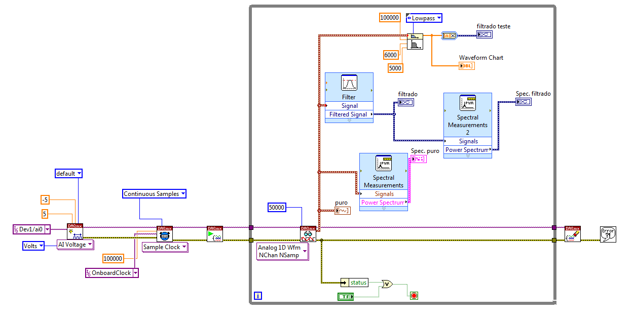
OK, here´s my problem. I can´t use of a Butterworth or a Chebyshev filter (or any type) to create a low-pass filter filter. I Don t know if I didn t understand it s parameters correctly or if I m set something wrong. When I use the ExpressVI filter, I get the result I want to, but when I use the function of Butterworth, it doesn´t work.
Can someone help me please?
I m sending the project I ve designed, so that you guys can see what I ve done.
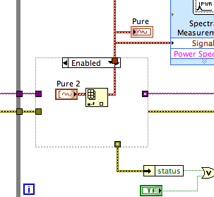
Here some explanations: the "puro" labeled graph is the pure I m signal generation.
The labeled graph "Spec. PURO"is the power spectrum of the signal current
The graph "filtrado" is the signal after going through a low pass filter in the express VI (which works fine) and the graphic "filtrado Spec" is the power of it s spectrum.
In the upper part of the loop is the function of Butterworth filter. I ve wired the pure data to its input signal and expect one out everything as the express VI creates, but he's not even conspire anything in the chart.
The windowed FIR filter VI generates the error-20023, which constitutes a violation of Nyquist. Because this VI returns only an error code and not the cluster of standard error, you must connect explicitly an indicator or manipulation to the error output.
The cause is that you have the frequency to zero. OR use a somewhat confusing nomenclature for the inputs of the filter frequency screw these detailed help says:
high cut-off frequency: fh is the high frequency in Hz. The default value is 0.45 Hz. The VI ignores this parameter when the type of filter (low pass) 0 or 1 (high-pass). When the filter type is 2 (bandpass) or 3 (Bandstop), high cut-off frequency: fh must be superior to low cut-off frequency: fl and respect theNyquist criterion.
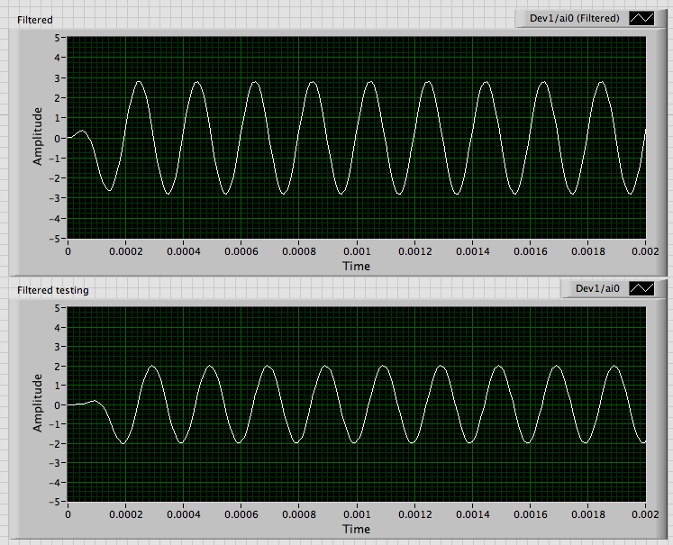
Thus, for the high pass filters and both low-pass cut-off frequency is the value wired to low cut-off frequency: fl. I regularly get this error. When I get strange results, I read the help and fix it. As soon as I wired 5000 to fl, the output looks like this:
The differences in amplitude and transitory initial are likely due to different specifications of filter.
The way I start it is to convert the flag to a Pure control, do default to the current value, and then put all the DAQmx screws in schema structures disable. I have disable placing the pure control (or a copy of it) in a case to permit the schema structure which has the DAQmx Read. Since you have only one data channel I added the Index table to get a unique waveform of the table. Then all the code signal analysis works.
Lynn
-
Low-pass filter before the NI 5112
Hello
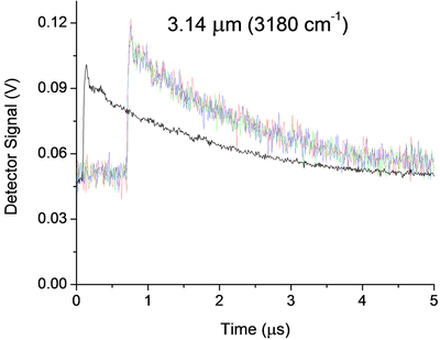
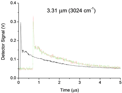
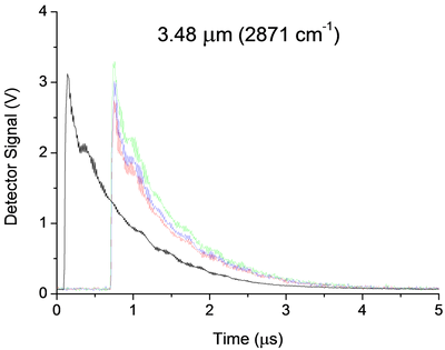
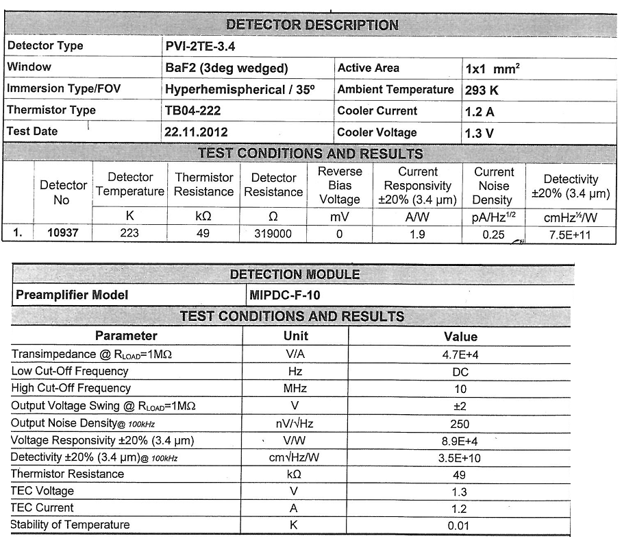
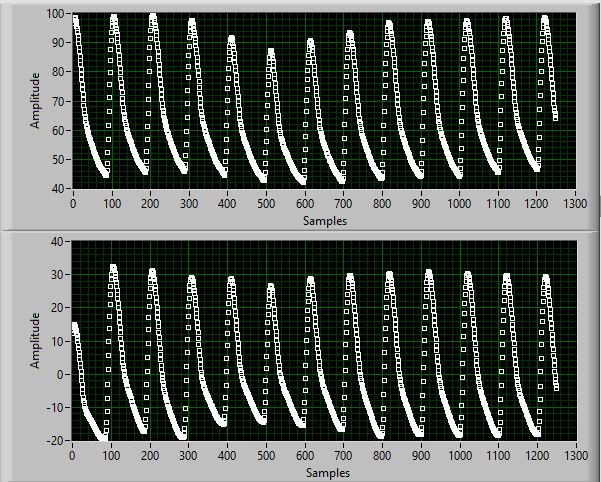
I currently use a 5112 AND measure the signal of an infrared detector in an experience of ring to the bottom of the cavity. Below are three examples of signals. My main question is how I can implement a low pass filter, passive preference, before my 5112 OR undistorted extremely my signal due to the impedance mismatch. Now a few details:
Some unique captures for each wavelength are shown in color, while average 25 pulses appears offset in black. The range and offset are chosen in each case in order to minimize the noise of "scanning". In the case of 3.14um, the noise that you see is about 25 times noise from scanning. They were taken without the limitation of BW and 100 ms/s mode.
The detector (Vigo MIPDC-F-10) has a bandwidth of 10 MHz. I think it is a low impedance and is intended to be harnessed with 50Ohms, however its documentation confuses me, and I'm waiting for a definitive answer from the provider. 2.4 part of the manual says 50Ohms recommended, however the Datasheet and our map calibration (below) seem to suggest 1 MOhm is recommended!
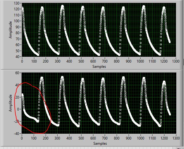
There are a few strange oscillations with a period of almost 180ns in our signal that I thought were due to the impedance mismatch existed in the system before I changed it:
-Detector
-1 metre 50 Ohm SMC Cable BNC (RG-174)
-Inline BNC connector
-meter 5, 75 Ohm BNC to BNC cable
-Digitizer, DC, no BW limit, 100 ms/s, 1MOhm | 30pF
When I saw this configuration, I knew something wasn't right and I even he modeled in LTSpice and he showed the same period of oscillations. But now, the Setup is:
-Detector
-1 metre 50 Ohm SMC Cable BNC (RG-174)
-BW digitizer, DC, limit, 100 ms/s, 50 Ohm
And we still have oscillations, even if the period seems to have changed to 320ns all about. These oscillations, which remain are 99%, probably due to our drop-down ring cavity experiment, however if anyone has recommendations on possible causes or ways I can confirm it is not because of my chain of detection they would be more than welcome!
Now, the main question. Between the 50 Ohm 1 meter cable and the scanner I would insert a low pass filter. The BW limit has helped reduce the noise, but it can certainly still be further reduced without any lose to our signal. That's because we cut the beginning of the signal and then measure just the the decay time, which is relatively long and smooth (1 to 2 times 1/e US). Thus, in the future I may even want to try to eliminate the oscillations 320ns, but I'm afraid that this much filtering will distort the signal too. Therefore, for the immediate future I'm just looking to 'replace' the filter BW 20 MHz, with something like 1 or 5 MHz.
Of course, I would disable the BW limit on the digitizer to avoid additional confusion, but nevertheless, I'm not sure how to approach the problem. Usually I do a lot of research and try different solutions. However, I don't have access to all components to this work, so everything should be ordered, and I don't have a lot of time to experiment. Ferrites seem like a possible solution, however not sure how effective they are at this low frequency or the way they work with coaxial cables. I know that the filter passes low RC base, but the 50Ohms (or 1MOhm | 30 pF if I change it) seem to make it impossible. I guess an op-amp based one might work, however the large input impedance is the impedance of coaxial cable... etc...
All of the recommendations of the technique or red resources wort would be welcome. Thanks for your time.
A possible way to separate your artifacts electric and the cavity is relatively simple. You take the data at three wavelengths. For each of them, make a simple exponential decay (for example exponential Fit.vi) adjustment to your data, then subtract this signal. You should have something that oscillates on an average. Compare the residual signals for all three wavelengths, either visually or with something like a power spectrum. Anything in the three is probably the electronic (and you could possibly model and subtract it rather than trying to eliminate it). This could break if the rise time of the signals are different, because that will include elements of different frequency.
I am not convinced that you need to filter your signal before taking data. As you said, any filter will distort your final signal. My preference would be to take the raw signal and apply a filtering in the analysis. LabVIEW has a rich filter, so you can experiment later. If you apply a filter before the digitization of data, you take you will never receive data. However, if you know that your data has no component of your proposed cut filter frequency, you should be good. An analysis of the power on your current spectrum should tell you this. Be careful. Your form of rise time may have information you want later. If you filter, you will probably slow it down.
Good luck! Let us know if you need more information.
-
Loss of information on the edges of the sample of low-pass filter
Hello
I use a low-pass filter elliptical command to address 6 to remove trend of signal in a measure of the pressure of data sampled before, however given that the program must deal with and calculate an index in a given period of time, I can't filter and store then the data for the calculation later.
The size of the sampe is this 1250 or 10secs data with sampling frequency value is 125 samples/s.
In the effort to eliminate the distortion of the filtered signal, I use a technique described for tag/add a start and a value final ampitude on the beginning and end of the sample of the same length (1250), I have also run the data in the order opposite to eliminate phase effects.
However I want to say is still a slight distortion that can be seen in the start menu of the sample; first of all, here with the loss of amplitude, but more often it's worse than that and distortion occurs at the end of time to time.
I have some experience of the DSP (but since 20 years ago!) and remembers Windowing may be a way, but I still think that the filter should not be so difficult to implement more I don't want to lose any information amplitude.
Any help would be appreciated.
See you soon,.
Kevyn
johnsold wrote:
..., you may need to use different techniqoes that are not in the information stored on the previous behavior of the signal.
Lynn
In some cases special where information that happened before all data you have is implicit, but data yo u have, you can go out with reflecting data about initial/final data set and then run the data through the filter first forward, then backward. After that mix data accompanying your data "pretend" and just look at the part that iss associated with the actuall data set.
Ben


Maybe you are looking for
-
Hello I am not able to download songs that I bought a few years ago. I don't see that this product has been paid. There are more artists that I paid in the past and are not available in my ITunes. is my attach. No idea how to solve out? Means of zaku
-
I've actually had this problem for over a year now with previous versions. The browser always crashes just after that I start it, but it seems to work fine in safe mode. I tried to reset the Firefox, disable all add-ons mode security and reinstall th
-
Hello A few days ago my iPhone gives me the message that my storage is full. I just deleted 2 value apps around 2 GB of data and literally a few seconds later I get exactly the same message, I have not downloaded anything in the meantime. also, when
-
(Redirect) Dell Latitude 10 Miracast 1.3 WDDM does not
Dell Latitude 10 Miracast WDDM 1.3 I have two Dell Latitude 10 tablets and I cannot either connect to the Netgear Push2TV adapter. They see and allow you to enter the code, but then nothing. These tablets came with a 8 win and I upgraded to win 8.1 p
-
Cannot set a default website in Google Chrome
Hello Cannot set the default Web site in Google Chrome. IE has been simply to go to the top of the page of google/right click / check the menu/internet options / and choose URL [google.com] to start by default. It is impossible for me to understand