ACQUISITION OF DATA NOR USB-6251
is it possible for the box USB-6251 to provide an output for a test set-up during playback of the inputs of the device even? for example: 10VAC Ridge to Ridge on the luminaire, mixed the sine and square wave signals of the luminaire to the data acquisition Toolbox.
Yes. The 6251 has two outputs analog and 16 analog inputs. Open finder example and looking for examples of both. Under input and output hardware > DAQmx > Syncronization > multifunctional, it is an example of analog inputs/outputs synched.
Tags: NI Software
Similar Questions
-
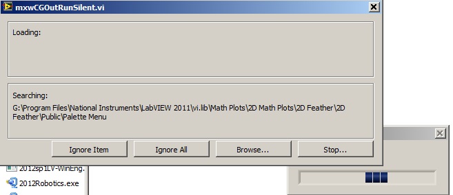
Acquisition of data NOR usb 6008: a strange problem: mxwcgoutrunsilent.VI is not respected
Expensive OR
Today, I bought an acquisition of data NOR usb 6008
and I'm using labview in 2011
the problem is appear when after I end the process of configuration of the i/o data acquisition Wizardthe following image shows the mxwcgoutrunsilent.VI is ignored and an error has occurred
someone can help provide this VI for me
What is the complete labview modules can also so I could do a real time data acquisition
Best regards
mangood,
You received an error code? If so, what is it? What version of NOR-DAQmx driver you have installed? It seems your driver potentially incorrectly installed, and you may need to reinstall the driver.
Here is the link to the latest version of the NOR-DAQmx driver: http://www.ni.com/download/ni-daqmx-9.8/4297/en/
-
Simultaneous to the AO and HAVE with the acquisition of data NOR USB 6001/MATLAB Toolbox
I am very new to data acquisition and bought a NI USB 6001 to start to learn. Because I can get free MATLAB through my University, I use Matlab data acquisition Toolkit as the data acquisition software.
My problem is that I get the following error message when I try to generate an AO (an LED voltage) signal and measure a signal I (voltage of a battery of 9V) simultaneously.
ATTENTION: This change is caused in the dump output data queue. Use queueOutputData for the queue data before the start of the object.
Hardware does not support the specified connection. Check the user manual of the device for the valid device routes and pinout.However to measure IA or by generating the AO each by themselves works perfectly well.
My Matlab script looks like this:
daq.getDevices;
s = DAQ.createSession ('or');
s.Rate = 1000;
s.DurationInSeconds = 10;
addAnalogInputChannel (s, 'Dev1', 'ai0', 'Voltage');
addAnalogOutputChannel (s, 'Dev1', 'ao0', 'Voltage');
aoVoltage = 1.8 + 0.1 * sin (linspace (0, 2 * pi, 10000))';
queueOutputData (s, aoVoltage);
s
startBackground (s);
Note that adding the channels HAVE and AO at the session also works, however I get the error mentioned at the start of the session. This is a limitation of my data acquisition hardware (I don't see something like that mentioned in the manual) or do I have to modify the script?
The pins connected for the LED are AO0 (+) and AO GND (-).
The pins connected to the battery are AI0 (+) and (-) AI4. (The problem is still there if I use the reference to the ground for AI)
6001 cannot make simultaneous tasks. Very standard limitation of the low-end hardware... just don't have on board computing resources to handle such things. Even the 621 x boards have only limited multitasking abilities.
Can intensify to a high range data acquisition ($$$) or buy a 2nd a low end and synchronize tasks in software (not as precise calendar). I've done two approaches, one is "best" really depends on demand... If low-cost or high-performance is a priority.
-
My acquisition of data NOR usb-6008, does not appear in labview after installing drivers
My DAQ does not appear in my labview program after installing the drivers. I can't add it to my program or anything like that. I installed 3 different drivers and updates, and it's still not appearing in labview. Is there something I'm missing or need to do yet?
Thank you
It seems that you have a damaged file somewhere in your installation. You will need to go into the control panel and select the option to repair the installation. You will need to run the repair twice due to a known problem. After that, you need to reinstall the NI_Daqmx 9.4.
Jacob K
-
Hello
Currently, we have two signals which are physically and logically linked together on the same line of data acquisition. The first, 'I' and the second signal, 'Q', are both related to "Ai6" (PIN 23) and "Ai GND" (Earth). However, when we probe the two lines coming our function "signal split", I drove Q by about 0.5ms. My question is, if these two lines are actually bound together physically and logically, then why are they phase shifted if they are both the same channel? They should be exact matches. I thought that the phase delay inter-channel occurs only in what concerns channels being read from data acquisition. I have attached a few screenshots as well.
Input signal is 20 kHz. Sampling rate is 40.5 kHz, number of samples/point is 1000.
Thank you.
Best,
Saami
System - Ultrawave Labs engineer
The board you are using is a multiplex. If you create several virtual channels, pointing to the same physical channel, we can enjoy this channel once for each channel. So what's happening essentially is that the physical channel was sampled once for channe 'I', then again for the channel 'Q' with a delay of a few milliseconds in between.
-
Acquisition of data NOR-9205 Assistant set up range of input voltage
How to configure the module NI9205 to use the +/-200mV input range.
I use a custom scale, and it seems that I can not get an accurate reading. I use a shunt current of 100 Ma (max 10A). So I custom balance setting to have 100 x + b. The current flowing in the device is 2 amps and I get a reading of 12-13 amps after custom scale. Now I think the module is configured to sample for the entrance of 10V and I get an error of resolution.
Hi therbert
Since your custom scale is 100 x, to work on the beach of +/-200 mV to your NI 9205 module you must configure your input signal of maximum and minimum range for +/-20 respectively.
According to the equation: Range.max * scale.slope = 200mV * 100 = 20V
This will automatically configure to the scope of the module +/-200 mV to verify you can access the channel DAQmx property node and look for the analog input > General Properties > advanced > Range property, this will let you know in what range is the functioning of the device.
Concerning
-
I know this has been asked to death, but I have not found an answer very clear on google or on the forums. I have an acquisition of data NI USB-6251 I want to interface with the help of C++. I have Visual Studio 2008 (or VS 9.0), but I don't have a Measurement Studio. I would avoid buying Measurement Studio if someone knows interfaces with Renault C++ sample codes?
If you DAQmx installed, you should be able to go to start > programs > National Instruments > NOR-DAQ > text in support of the Code and find some relevant examples there.
-
locking using NI USB-6251 amplifier
Hi all:
I'm in the very initial stages of development of spectroscopy (FMS) frequency modulation experience on my set-up of already existing absorption spectroscopy. I know that I'll need an amplifier to lock to select the signal at a specific frequency. I already have an acquisition card of NI USB-6251 data which works very well and I've used for my experiments of absorption spectroscopy. I was wondering if there is a way to create an amplifier to locking vi which uses the NI USB 6251 casing and would do what I need for my FMS experience. I try to avoid buying another instrument, if I do not need.
Anyone who is familiar with amplifier locking vi and see if I can put it with my USB NI 6251? Thank you!
Alfredo
Herea link to the use of an amplifier to locking using LabVIEW. However these specific VI were designed to use our acquiring dynamic signals of maps that isn't the 6251. You can try using a simple bandpass filter in the software, but it is certainly not an ideal situation in any stretch of the imagination. But with only the 6251, it is certainly an option.
Kind regards
Brian P
-
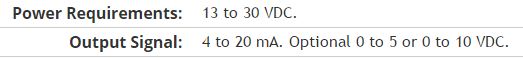
Here is my sensor
Pressure sensorHere's the DAQ data sheet:
Here are my issues:
First of all I don't know what is LO and HI exactly in the DAQ 9219 material.
Second, I don't know what pin code I should connect the DAQ sensor signal wire. PIN 4 or 5 pin? The sensor has three pins, and I guess I should connect the other two wires to the power supply.
Thirdly how to calibrate the sensor. In labview choose voltage in the wizard?I'm pretty new in this acquisition of data and I need your help.
Thank you
Hi SilasIII,
Hmm well 3 sons are probably on the ground, the power and the return signal. The datasheet for the sensor says:
First of all, you need to know which model you have (4-20mA, 0 - 5V or 0-10VDC). HI refers to the return signal, LO essentially means the land of the food that feeds the sensor. Then, you must get the 13-30 VDC supply. I don't think this should be too complicated and can be a simple wall DC power. You can learn how to create a custom in DAQmx scale. I hope that this is a starting point.
Kind regards
Eric
-
How to reduce the noise in an acquisition of data USB-6251
Hello world!!!
I have a few questions about a system that I have developed using a data acquisition OR usb card 6251. The pressure control system.
First of all, the signals are acquired using an Omegadyne pressure transducer. (Typically, the signals are between 0.1 mV and 38 mV, pressure is between 0 to 50 lb/PO2). The transducer is connected to the usb-6251 daq card (I use pinout of the 1 and 2 for the signal acquisition, also, I have a 100 K resistor between pin 2 and 3) and the card is connected directly to the computer. In addition, I have an omega counter, I use it only to see pressure on the screen. But long term, it will be useless.
One of the problems I have found is the noise, the measured voltage values change much. Even if the figures in the player screen do not change so much... (or do not change)
The system should regulate the pressure so if every second it changes a lot, the system did not work properly. How can I make the technical more similar to that of the meter? In the labview program that I use, I use a block 'base DC', he reduced noisy signals a lot, but not enough that experience, I need more stable values.Thank you
I don't mean in the /manuals of broaching and do not open .doc from unknown sources files (a chart single .png is fine ;-))
However, I guess you already measured in differential mode and the 100 k is a path for the currents of polarization forever
The reason why your counter is stable can be the fact, that she has a generation to filter low pass (on average) with a big enough constant time.
First things to do:
You did it that there is a filter anti-aliasing suitable for your sampling rate?
Read the signal on at least 100 ms (120ms in line 60 Hz) possible higher sampling rate and take a look at the signal (and display a chart as a .png or .jpg image)
This will give you an idea how the signal looks the same. Then you can choose a filter according to your system and the signal or other investigations to do not even catch the noise (groundloops, protection...)
You can use an example on the screws or the testpanel to the MAX for this measure. (Personally, I prefer a similar scope :-))
-
Need a new acquisition of data USB multifunction device
Hello
Currently I use a PCIe - 6321 Multifunction DAQ hardware to control my stepper motor. I need to change the PCIe - 6321 and use the engine with a device for the acquisition of data USB multifunction bit PCIe - 6321. I'm not sure which USB model to select. Can I please get help about the choice of the right MIO USB data acquisition device that works similar to the PCIe - 6321.
Thank you
Bharath J S
The 6212 differs from the 6321 somewhat on the digital side, which probably you use to control your stepper motor. For example, it was only software DIO timed tasks and has only 2 counters with a set of features (e.g. no output meter in the buffer).
Best regards
-
Looking for a way to mount an acquisition of data USB-6008
Anyone has a suggestion for an acquisition of data USB-6008 mounted on a Panel. I use it for a system where it should not be loose. I have a few ideas, but hope that someone smarter already has a good solution.
Thank you
It is not a robust application, but the box will be moved and I don't want it put in the open air. I simply put a velcro pad on the back and the atttaching in this way. Should be all I need.
-
How I choose the USB-6251 (full speed or high speed) data transfer rate?
Hi, this is bose, FAE Samsung in Korea.
I saw the USB-6251 specifications that it transfer data at high speed or full speed.
How can I select speed mode?
It depends on computer?
Thank you.
Fairly certain, it is totally dependent on the USB hub.
-
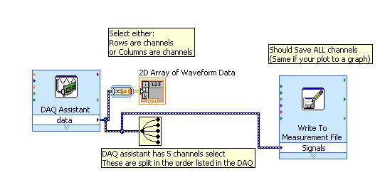
I did separate VI for reading signals from several channels on a map of NI USB-6251. I would like to combine these in a VI VI alone so that they can run that at the same time, however, there is an error if there is more that a single DAQ Assistant in the same--> error-50103 VI was held at DAQmx controls Task.vi:32 (the specified resource is reserved. The operation could not be performed as indicated.)
All the inputs of channel must then be read in with a single DAQ Assistant, but all of the data on different channels are not separated. Can save this data in a matrix or otherwise manageable which allow to facilitate the analysis of the data from the separate channel entries?
I tried to view the data in a file of measures, but then when I tried InPort data, I could all the data I wanted.
Hi AggieGirl,
Good afternoon and I hope that your well today.
First of all, you will not be able to have more than one DAQ Assistant by input analog or analog output task because the device has only one of each. So, you must have a DAQ task to HAVE and AO. (This is not the case for DIO static).
There is far from split signals using the express VI - signal splitter.
When you say you saved this file and it does not work, how it did not work? The Express VI - save a file of measures needed to manage multiple waveforms. Can send you your code & explain more about what was not OK on the file?
Thank you
-
Generation and acquisition at the same time, acquisition of data USB-6356
Hello
I have a VI how is able to read entries with a USB DAQ-6356 and I use a generator of signals 'Agilent 33522 A '. I want to generate and acquire with the acquisition of data.
In fact it works but not well, the frequency is not very stable and does not stop the 2nd loop with 1 (2nd is generating, 1 is Acquire).
Thanks in advance

P.S my VI isn't a state machine true because I need to fight against it at the moment.
OK, so you're at 3 ms/s in writing and reading at 1.25Ms / sec and you wonder why he has a little difference in the frequency set? Ideally, you want to read and write to share a sample clock but by selecting at least the same frequency clock (or one that is one multiple of the other) would go a long way to fixing this source of your error.
The second source of error: you generate a contineous waveform. unless you select 'whole number of cycles' there is a discontinuity when the end is reached at an arbitrary phase and the phase is reset to zero at the beginning of the wave. DAQ assistant writing can "Use Waveform Timing" to adapt its sync settings to the dt waveform and the number of samples.
Maybe you are looking for
-
What battery for Satellite X 200 series
Hi, I wanted to buy an extended battery for my X 200 satellite. I called toshiba, as I was still not sure of the compatibility. I was told to get a PA3357U-3BRL. Now, I have a battery that needs to be exchanged and does not fit. Now, tell me. What la
-
Junk e-mail filtering, continues after activate spam filtering is unchecked.
I don't want E-mail on El Capitan to filter all mail to the junk e-mail folder. I unchecked enable mail junk filtering. I restarted Mail since unchecking filtering. I rebooted since unchecking filtering. As he did when the checked enable spam filteri
-
Satellite A500 - how to move from Vista 64 bit to 32 bit?
Hei guys,. Recently, I bought my new A500 series - 14 c and installed the 64-bit version of Vista. What is happening is that I later discovered that a USB sound card that I use doesn't have vista64 drivers yet, so I wanted to reinstall the OS and cho
-
It's been 6 months the question has been asked, is still available for Windows 8?
-
My computer is defragged all files that it can. You, please, will address the following questions:
My computer is defragged all files that it can. You, please, will address the following questions: Fragments of files in file size that cannot be defragmented5 46 MB \WINDOWS\Installer\2b0c16e.msp6 73 MB \WINDOWS\SoftwareDistribution\DataStore\DataS