How thre cutoff frequency
Hi all
Please find the program in the attachment. I am interested in a specific frequency band, for example, Hz 101 to 103 Hz and peak in the frequency spectrum you're looking for is probably to 102Hz. What I did is to put two filters as a band-pass filter before the FFT, as shown in the picture. Unfortunately, there is a high frequency of componentat at 100 Hz (approximately 5 times the size of 102Hz), similarly I uses the high-pass filter to 101Hz and select order 10. It picks up again the frequency of 100 Hz. is possible to cut the frequency, implemented the frequency range of exatly for research?
Thank you very much
Alan
Use the data reduction Cut Out module. It works by zero samples ' ing in the block, so you will need to calculate what samples corresponds to each line frequency. The list module can help you to see the frequency baseline values exactly.
For example, at a sampling frequency of 11,025 KHz, 4096 block size, the block of TFF resulting is 2048 samples. Example 39 is 99,59 Hz to 40 Hz 102,28 sample. I used the 40-45 of cut-off values to see the 6 lines of 102.28 and more.
Tags: NI Products
Similar Questions
-
Agilent 33250 A driving, how to avoid frequency rounded up/down
Hello
I want to control an Agilent 33250 A generator using LabVIEW to obtain different waveforms with a specific frequency, amplitude values. I use Agilent 33XXX Series.lvlib: Configure Standard Waveform.vi
My problem is that when I give a value of frequency of 79 999 Hz 996 (79. 999 996 MHz) for example, the program will round the value to 80 MHz. How can I give a frequency value, as above, without rounding upwards or downwards?
Thanks in advance.
Look at the VI and see how is the string format. The result of the conversion of a string to the probe and see what happened to the instrument.
-
How to increase frequency resolution in the power spectrum?
All,
I work on the analysis of data GET vi, and manage mucho when it comes to display a simple power spectrum which gives a precise simulation of sine wave frequency I use now. Most of the brain waves are between 1 to 50 Hz, and so I try to get a resolution of at least 1 Hz frequency. However, no matter what I do (increase the sampling frequency, use different sub vi and blocks), the chart plot only in frequency of 10 Hz increments. I know this must be a simple problem, but I can not find good documentation on this and would appreciate any advice anyone could give on this problem. I'm racking my brain here!
Nick
You need to acquire a second data to get the 1 Hz resolution. The increase in sampling rate only increases the bandwidth that covers the FFT.
Frequency resolution = 1/sampling
Scale of frequency rate of sampling/2 =
For your application, you will need to have a sample of at least 100 Hz rate. At this rate, you must purchase 100 samples to get the 1 Hz resolution. At the 1 kHz sampling rate, you will need to acquire 1000 points for the 1 Hz resolution.
-
How current function (frequency) of the output to the last value in HP8510c
Hello
I have been using HP8510c for the calculation of the Q factor, the problem is, I need every S21 801 frequency values I get the raw data, in order to get the loaded Q factor.
I use the STIMULUS as "RAMP" just for your information, which is also the default option.
I couldn't understand this so, what I thought to do was get the frequency start and end and he interpolated between 801 points.
Now I'm using vi 'Ouput function Active' that displays the value of any function, I chose. So if I select start and use this vi, he's going to show me the frequency of 'start '. But the problem is that the I don't get the whole figure.
If it appears on the screen
START = 4.46647456635 Ghz
It will be output as
4.46640000000 Ghz
It is not that the GPIB bus truncates the data, I feel that the HP8510 firmware is configured to do this. What is another way by which we can get the value of the exact frequency?
The accuracy is ideal for the accurate measurement of factor Q.
LabVIEW does not otherwise deal with him. Your VI isn't close to being correct since you connected the County return since writing to the entrance of count bytes to read. There is absolutely no connection between the number of bytes you write and the number of bytes that the instrument will return. The number of bytes of the value to a number and see if it starts to work magically.
-
How Smartphones blackBerry frequency search new phone email?
Hello
On my computer with Windows Mail, there is an option for how many times I want the program to check for new messages, for example: check every 15 minutes. Anyone know how many times the blackberry 8900 check new messages, or if there is an option to change the setting?
Thank you, Matthew
BIS accounts on a systematic POP mail server will check every 15 minutes and push new email, then check again in two minutes and push new messages and repeat that during two rounds of two minutes until no new message is found and then go back to the cycle of 15 min, etc., rinse and repeat.
BIS IMAP accounts are instant push. Google and Yahool mail are instant.
There are no options for changing the cycle. It is determined by the type of the mail server you are using.
-
How three type of the structure of the tab in the apex
Hi all
I have a requirement where I need to organize the tabs. but the levels are 3.
Apex provides only 2 level tab structure, I am trying to host 3 rd level with using the left menu, which can be shared by all pages.
or
I'm looking for level3 navigation... which makes the user to move easily from the application.
Please post your suggestions how.Gregory,
Lists are created Home > Application Builder > Application 99999 > shared components > lists. Each list entry then target a page. Once your list is built with all the necessary entries, add to the list as a region to each page that are targets of the entry in the list. Generally, I put my list at the top of the page by giving it a low sequence.
In each entry of the list, set the entry of current list > list input current for the Condition on the same page as the target. This will highlight the entry from the list when you click it.
When you set your list, play with the model list to determine which best meets your needs and requirements. List button model provides that a 3rd level of the navigation and the list of vertical side bar provide navigation to the left of your page.
On the secondary tab that calls one of your goals from the list, it will take change in the section tab also run for Pages so that the secondary tab keeps up-to-date when navigating through the list. This parameter must include all of your pages list target, separated by commas, IE 1,2,3,4...
Jeff
Published by: jwellsnh on October 28, 2009 09:00
-
How to control frequency, a member server, the time of synchronization to a domain?
I have a domain with two servers and a domain controller or a member server. Synchronization DC his time with an external source and provides the source of time for the field. Generally all works as expected. However, the time on the Member Server derives from the network. "Time net/set/y" running manually on the member server corrects the Member Server, but it moves again.
A solution would be to manually run a script on the Member Server, every hour to make sure that it is time remains synchronized. However is there a way to configure the Member Server so that it automatically keeps in sync with the network it's time?
Environment: Server Win 2008 R2, s client pc Win 7
This issue is beyond the scope of this site and must be placed on Technet or MSDN
-
How determine the crossover frequency
I'm having a hard time to understand how the high-pass filter determines vs high frequency. What value it measures. ? A change of RGB values or contrast? I see the sharpness of words or blur, but what values determine the amount of blur or sharpening? Is there and the actual frequency being high or is it just a metaphor to compare it to the audio crossover?
No details on the workings of this filter is appreciated.
A few additional explanations:
Audio signals:
frequency = cycles per second
It is the frequency in the time domain.
An arbitrary signal can be represented by a set of harmonic signals (sine, cosine)
In addition, some DC (direct current, non-periodic component).
A typical high-pass filter for audio signals:
The cut-off frequency fc is at the transition between the increase in gain
(low frequencies) and fixed gain 1.0 (high frequency).
frequency reduction (mitigation)
CF 0.01 0.01
CF 0.10 0.1
CF 1,00 0.707
10.0 fc 1.0
100 CF 1.0A typical high-pass filter for digital images:
frequency = cycles per unit of length or (better) cycles per pixel
It is the frequency in the space field.
The highest frequency is 0.5 cycles per pixel (alternation of black and white pixels)
A line of arbitray in a digital image can be represented by a set of harmonic signals
In addition, DC-part.
Each channel that r, G, B is filtered individually, one after the other.
Frequency and gain are as above.A high pass filter applies to mitigation<1 to="" low="" frequency="" signal="">
and removes the DC component entirely. This would result in a black background.
Therefore, the background is extended to R = G = B = 128 (8 bits per channel) or
R = G = B = 0.5 (standard).Edges contain stronger high-frequency components. These are preserved.
http://en.Wikipedia.org/wiki/high-pass_filter
In this doc, we find a simple implementation:
y [0]: = x [0]
for i from 1 to n
y [i]: = a * y [i-1] + a * (x [i] - x [i-1])
return yx [i] are values of R (or G or B) row in column i in the original image
y [i] are values of R (or G or B) on the same line in column I after filtering.
Factor (a) indirectly contains the cutoff frequency.
This example does not yet apply the SHIFT R = G = B = 128.The implementation can be different (filter not recursive instead of recursive, as indicated above,
higher order instead of first order, using a filter kernel 3 * 3 5 * 5 pixels instead of work
in each row independently).I'm not trying to explain how Photoshop! There are so many alternatives.
Cordially - Gernot Hoffmann
-
Hello:
I am on the show dealing with the identification of the system. The process is as below:
First of all, I use a sine sweep signal (bandwidth is 0 to 50 Hz) to stimulate the actuator;
Second, I use a low-pass filter (the cutoff frequency is 45 Hz) to filter the response signal, like the image below.
-
How can I get the Coefficients of scaling for the Butterworth filter FPGA version
I am trying to program a FPGA application where I need to be able to change the cutoff frequency of the filter. I see that I can do a terminal for the coefficients of the filter on the VI express Butterworth filter, but how to generate the coefficients of different cut-off frequencies of filter? When I use the VI of Coefficients of Butterworth host-side small floating-point values rather than the large fixed point values I see on the side turns FPGAS.
Thank you
David R. Asher
Hi David,
8.5 or 8.6, there is an example of navigation that contains the Subvi design filter you need:
examples\R Series\FPGA Fundamentals\Analysis and Control\Filter and filter Butterworth Reconfigurable DC-RMS\Using-R - series.lvproj
In LabVIEW 2009, there is a new palette in my computer: Interface FPGA > scaling, with a new VI of Coefficients of Butterworth on this subject. Who will produce the coefficients quantified, you need in the format expected by the FPGA Butterworth filter.
Kind regards
Jim
-
How to set the low-pass analog input (smoothing) on my DAQ configuration filter?
I read the following of the PXI-6251 manaual:
"On some devices, the cut-off is fixed. On other devices, this filter is programmable and can be switched to a lower frequency. For example, the hardware OR of the 628 x have a programmable filter with a cutoff frequency of 40 kHz that can be activated. »
It does not explain how you know this value. So, I have the following questions:
1. How will I know what the cutoff freq is on my device?
2. How do I know if its programmable?
3. how this program if it is programmable?
I use the PXI-6251 in conjunction with the PXI-1031.
Thank you very much.
The PXI-6251 has no anti-aliasing/programmable filter. Bandwidth (-3 dB) small signal from the 6251 is 1.7 MHz.You will find these information in the specifications manual.
If you need a filter, you must add the signal conditioning yourself.
The 628 x M high precision tips are the only cards of the series M 'programmable' low pass filter. Check this KB for more details.
I hope this helps.
Luca
-
How to get data not filtered as o/p of the low-pass filter Group
Hello
IM new to Labview and exploring it.
IM implementation of a system in which I need to use a LPF and a series of filter pass band.
The filtered o/p of the LPF is as I / p for 1 GMP...
Later, the o/p UNFILTERED 1st BPF is as I / p for 2nd GMP.
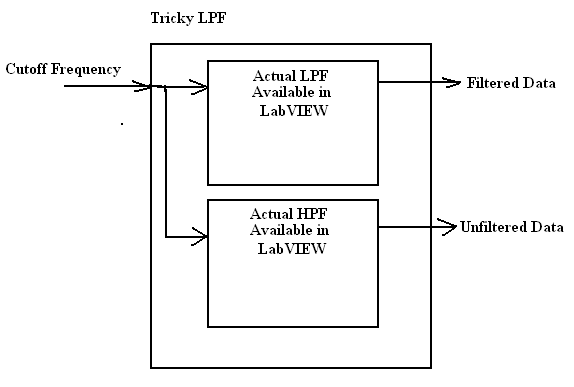
The problem im facing is: I do not see any box in treatment that gives the data filtered or unfiltered together in the time domain of the signal.
Could you please help me with this asap... desperately need your help.
Thank you
PSADAP
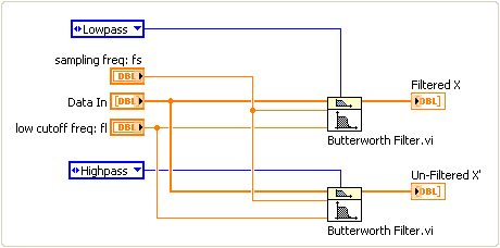
There is not direct the tool to do this, but there is a solution to your needs.
Say that if you use a LPF (with cutoff frequency, say 50 Hz), now to get blocked (UNFILTERED in your terminology) signal, set a HPF (with cutoff frequency of 50 Hz).
See the block diagram
-
How to get all netwok available provider mode list & network to all providers in blackberry?
Hello
How to get all the list of available network provider & fashion network (2G or 3G) as all providers in blackberry?
I read class RadioInfo he methods getNumberOfNetworks() y & getNetworkName() help I got from the available networks list but still not get all providers network mode.
Any body knows then please help me

Is it possible or not in Blackberry please tell me...
Please see this link
http://supportforums.BlackBerry.com/T5/Java-development/how-to-find-frequency-band-of-cureent-networ... -
Hiring of Eloqua people - how do you know if they "know" Eloqua?
Hi all
I am currently trying to hire some experts Eloqua (junior, specialist and Manager to be precise). I can't really get to know the experience of what the people is with Eloqua without meeting face to face and really dig in.
What I'm asking is, if someone created a questionnaire, or 'task' for an applicant to complete that would really give me an idea of their experience with Eloqua?
Thank you
Kevin
While interviewing for Eloqua jobs last year, I think that a lot of people have been faced with this same problem. I came across one was a good way to eliminate those who did not really know the platform. She asked me to tell him the biggest mistakes of top 3 that I had done in Eloqua. everyone has made mistakes in using bad synchronization and create hundreds of jobs in the SF to the sending of e-mail to the wrong list. If you ask about the errors that they facts that it will show that they know the product and chances are that they won't make those mistakes again, hopefully, they have learned their lesson.
Wondering if they have never setup a data clean program or ask them to describe in detail how they have implemented a natural program, what feeders or exclude whether they use, how they manage frequency CASL or by e-mail, ask email deliverabilty and how they track. Get really specific and if they can't answer or don't know what one of these things is that they are not a good fit. This could also be a good way to just see what other companies are doing and maybe get some advice on how to implement things yourself.
I hope this helps a little.
-
How to know how much ram my pc can manage?
Hello... I have a hp with the specifications of the image below and I want to know how much Ram can I put in this machine and how much speed/frequency can have the Ram (if it supports 1333 MHZ)?
My apologies mate, there were a few series dv6-1300 that was shipped with the GM45 chipset which has native DDR2/DDR3... This information is correct, it is a function of the chipset... Check this box... http://Ark.Intel.com/chipset.aspx?FamilyId=35515
I understand that you have upgraded processor Intel X 9100, which means that the chipset works now at 1066 MHz FSB of... So I still don't see that you can pass to 8 GB memory bus using PC3-10600 memory runs at 1066 MHz...

Maybe you are looking for
-
Why my computer takes so long to start?
When I hit the Start button, my computer freezes on the screen hp for about 15 minutes before the logon screen appears. Start-up had previously taken about 1-2 minutes, and then one day it started to take 15 and has done since then. What can be done
-
I click on save a file.The download window appear.Mozilla froze before the download icon.I close and open it and it froze again.Restart my computer.Open Mozilla and it works.Have to do it every time I have to download a file.
-
Permissions on removable SD card Android AT200 value read-only
Recently, removale on my at200 SD card has been set to read only for the applications of all but a few. This means that when you change or try to save, copy docs on the SD card, I get the message "not enough of permissions. Any amendment of these app
-
Why my HP printer does not print gibberish when I try to print information from this forum?
Why my HP printer prints on gibberish when I try to print information from this forum and how do I fix this?
-
Virgin cancelled blackBerry on curve 8520 smartphones...
Hey guys, ive been having a time of torrid, trying to get my head around this. Virgin have been absolutely disastrous in their attempts to help me and I just need someone to answer a few questions if you want to be so nice. I bought a £15 per month c