How to compare analog input signals?
Hi all
I use PCIe6363 DAQ to collect the analog input signals. Mode of input signal is continuous and single channel several example. The sampling frequency is 2 ms/s, number of sample 100KS or less. This means DAQ 100KS of collect and draw a line/curve. I want to compare the two curves. The problem is DAQ continuously collects data and plot also continuously. Would you please is it possible to compare the curves of this operation continuous operation. The main goal is to justify whether or not the signal of incomeing maintain consistency.
Thank you very much
Azim
You can store a waveform in a shift register. Then you have in memory compared to the new waveform.
Tags: NI Hardware
Similar Questions
-
How do I get the analog input signal and send it to output analog (real time)
Hello world
I do a simple task in Visual C++ and I use PCI-6221(37 pin).
Basically, I want to send the same signal of "analog input" to the "analog output".
at the same time (or almost), to make real-time application.
Can someone provide me with sample program please.
I would be grateful if you could provide me with the great tutorial that explains
step by step everything about NOR-DAQmx for C/C++ programming.
Best regards
Khassan
This is my code in C++, you can optimize it if that seems too messy. This code reads the analog input signals and exports it through the analog outputs.
To make this code additional work of the directories include and library directories must be added to OR.
I hope it helps someone.
#include
#include
#include "NIDAQmx.h".
#include#define DAQmxErrChk (functionCall) {if (DAQmxFailed (error = (functionCall))) {goto error ;}}
int main (int argc, char * argv [])
{
Int32 error = 0;
TaskHandle taskHandleRead = 0, taskHandleWrite = 0;
Read Int32 = 0;
float64 context [1000];
char errBuffRead [2048] = {'\0'};
char errBuffWrite [2048] = {'\0'};
bool32 done = 0;
Int32 wrote;DAQmxErrChk (DAQmxCreateTask("",&taskHandleRead));
DAQmxErrChk (DAQmxCreateAIVoltageChan(taskHandleRead,"Dev1/ai0","",DAQmx_Val_Cfg_Default,-10.0,10.0,DAQmx_Val_Volts,NULL));
DAQmxErrChk (DAQmxCfgSampClkTiming(taskHandleRead,"",100.0,DAQmx_Val_Rising,DAQmx_Val_ContSamps,0));
DAQmxErrChk (DAQmxCreateTask("",&taskHandleWrite));
DAQmxErrChk (DAQmxCreateAOVoltageChan(taskHandleWrite,"Dev1/ao0","",-10.0,10.0,DAQmx_Val_Volts,NULL));
DAQmxErrChk (DAQmxCfgSampClkTiming(taskHandleWrite,"ai/SampleClock",100.0,DAQmx_Val_Rising,DAQmx_Val_ContSamps,1000));DAQmxErrChk (DAQmxStartTask (taskHandleRead));
DAQmxErrChk (DAQmxStartTask (taskHandleWrite));While (! fact &! _kbhit())
{
DAQmxErrChk (DAQmxReadAnalogF64(taskHandleRead,1,10,DAQmx_Val_GroupByScanNumber,dataRead,1000,&read,));
DAQmxErrChk (DAQmxWriteAnalogF64(taskHandleWrite,read,0,10.0,DAQmx_Val_GroupByChannel,dataRead,&written,));
}
_getch();Error:
If (DAQmxFailed (error)){
DAQmxGetExtendedErrorInfo (errBuffRead, 2048);
DAQmxGetExtendedErrorInfo (errBuffWrite, 2048);
}
If (taskHandleRead! = 0){
DAQmxStopTask (taskHandleRead);
DAQmxClearTask (taskHandleRead);
}
If (taskHandleWrite! = 0){
DAQmxStopTask (taskHandleWrite);
DAQmxClearTask (taskHandleWrite);
}
If {(DAQmxFailed (error))
printf ("error DAQmx: %s\n",errBuffRead); ")
printf ("error DAQmx: %s\n",errBuffWrite); ")
}
printf ("end of the program, press the Enter key to quit\n");
GetChar ();
return 0;
} -
USB-6211: analog input signal affecting another of the same map AI
Hello
I use the DAQ-nor-6211 map and DAQmx features to read a hammer and a signal of the accelerometer and then use other LabView functions to make the FFT of these analog input signals. However, it seems that the analog inputs where the hammer and the accelerometer are connected generate a kind of noise or influence in other entries of this data that is not connected to any other sensor acquisition board.
I've had different experiences in order to check if the problem is with reading the card: put the accelerometer and hit the dog in another table where the DAQ card table was located (to avoid the vibrations on the map and a possible noise), ai1 entry was logged on the differential mode on the dog and the ai4 of entry is connected to the output (z axis) of the accelerometer. The other 2 ai2 and ai3, entries that can also be read by my LabView program, are open (i. e., any other sensor is connected to the card). When the structure where the accelerometer is located is struck by the hammer, the signal of ai2 ("x axis" seen in the first attached document) has a curve (on the time domain) which initialize almost at the same time that the hammer and the a3 of entry has a weak signal, but with the swing as well as the signal of ai4. The document "hammer ai1 + z_axis connected_ _x_axis disconnected ai2 + y_axis ai3 ai4" images that I captured the chart created in LabView. On these graphs, it is possible to check on the FFT the ai3 signal and ai4 has the same behavior (with different intensities), and enlarged figure of time domain image, we can see that the signal of ai2 increase almost at the same time of the signal of the hammer (ai1). The signal picked up by the sensors are probably creating a sort of noise on open entries ai2 and ai3.
Another experiment was conducted to check if the signal from a single entry that may affect the signal read from each other near the entrances: the DAQmx task Create channel had a physical channel has changed: ai3 entry has been modified by ai7 (maintain the same connection mode: differential), and the results are visible on the second attached document. In the graphs obtained in this experiment, it seems that the entrance of the hammer (ai1) affects the signal of input ai2 and ai7, which are not connected. And the ai4 signal does not seem to influence the other inputs, because he has a different curve on the graph of the FFT.
The same experiment was conducted using the CSR connection (change threads and create the DAQmx Channel Configuration), but the results were the same as those found using differential connection.
Finally, if the output of the accelerometer is connected on the ai2, the signal of the other open entries ai4 and ai7 seem to be affected by the signal of the accelerometer on ai2 (last document attached).
Could you tell me if the problem I encounter is caused by the DAQ card with this information that I gave to you? And if the answer is Yes, do you know if there is a way to avoid this noise create in one entry on the other hand, it please?
Thank you
Maybe Ghosting or crosstalk? Just an idea.
-
How to read the NI 9201 Module lab mode analog input signal
Hi all
IAM using the module Crio-9012 real-time controller
ND iam using NOR-9201 for entry and exit of NI9263 for
I have configures cRIO 9012 on my Pc
But how I'll take analog input using the module NOR-9201
Thank you
TC
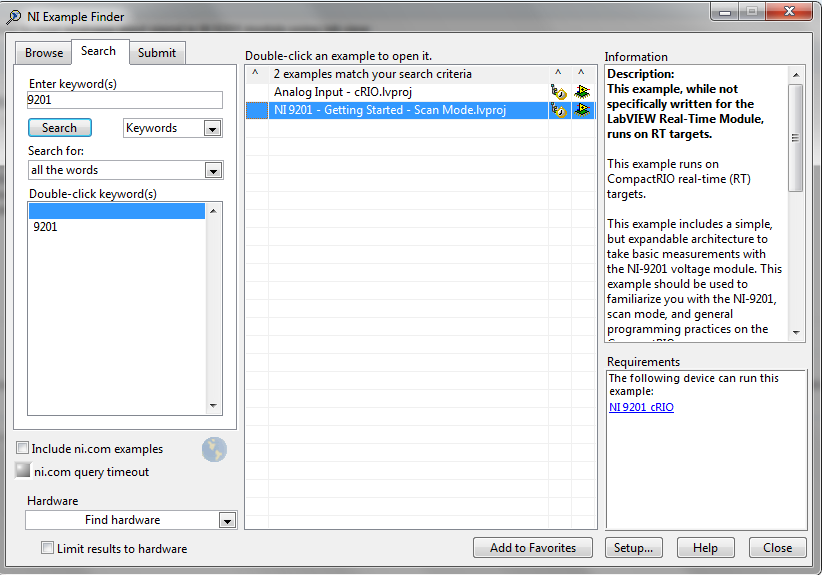
Hello
I recommend you take a look at the following examples in the example Finder LabVIEW. If you go to help--> find examples, you will see this window. Just search 9201 and you will see 2 examples:
I hope this helps!
-
How to get analog tacho signal in card PCI-6250 OR
Dear all,
IAM using Labview 8.6.1 and map NI PCI-6250. In my application, I need to get the power spectrum of the order for a given speed and signal of the accelerometer. So iam using labview example program command power spectrum(Analog_Tacho).VI. In my PCI6250 card, I have configured AI0 as the accelerometer signal and AI 1 as speed for tacho signal analog signal. In this sample program I can get the signal Amplitude of had it, but I can't able to get the speed profile. For iam speed using the encoder, encode this pulse digital I connected to the analog channel 1. If this connection is correct? Instead of giving digital impulses directly I tried the analog signal 0 - 10v for 0-based-1500 rpm. This configuration also does not work. Encoder PPR is 1000. Can someone help me solve my problem.
Kind regards
Vijay.
At 1800 rpm spin you at 30 Hz. for your encoder impulses come to 30 000 Hz. You must try the channel analog encoder to 100,000 samples per second or more. The chart of your analog inputs on a graph of time waveform to see if you get a clean signal.
With tacho analog vi, you will need to provide the number of pulses per turn, so it can determine the correct speed.
-
NI USB - 6259 BNC DAQ: analog input signal cross on the question
Hello
I use the NI USB-6259 BNC DAQ unit to acquire a four-channel analog signal, and I'm having a problem with a signal that affect others. The circuit, I am running is:
I have a wire connected to a battery (two AA batteries at ~1.5V), which then feeds the signal cable to a BNC cable, which feeds an analog BNC of data acquisition channel. The field of NBC feeds to another wire, which is attached to a conductive plate. The idea is this: when I touch the wire connected to the battery for the metal plate, I complete the circuit and thus get a binary not anything at all about 3V. When I tested with an osciloscope using two channels (each earth connection to the metal plate) I get independent steps whenever I touch any of the sons of the respective batteries to the metal plate (i.e. it works as expected). However, when I use it with data acquisition, whenever I touch a wire, I get a response in all other channels (3 others), even if their respective sons does not touch the metal plate.
No one knows why this happens, and how I might be able to stop this 'cross-talk '?
Thank you
Veritas
I see, and you're right. This request will have trouble with crosstalk. Luckily the ground channel thing should help you.
Configure your DAQ to collect twice as many channels as you need. Connect your wires in the odd channels and short circuit (ground) the entries of those even.
Now when you scan the channels it will always technically crosstalk, but it will come from a channel to the ground so that there will be nothing to interfere with your measurements.
At least that's the theory.

-
How to compare two .tdms signals different files?
I develop a lie detection system in labview.so Inorder for that I need to compare the physiological threshold signals in the file .tdms with signals that I acquire the object for each question asked.i continuelsy use breathing and heart beat monitor as well as the sensorDAQ to acuire the physiological signals.so that are the function I should make use of? I have the following tools
1 advanced signal processing toolkit
2 adaptive filter toolkit
3. digital filter design toolkit
4 research biomedical toolkit
Please give advise me on this.
Thank you.
Systems of lie detector (polygraph) generally work looking at physiological responses to the baseline subjects own and this in real time. You can use a file that represents the stored "database" for the subject, but the overall environment, the circumstances, the general State of the subject, etc. is perhaps not sufficiently similar to easily see the subtle changes.
From the stored file, you can determine a set of parameters or thresholds that indicate "normal, relaxed" for each signal. You can play the file in your LabVIEW program, treat each channel and save these settings. Then when you have the new data, you can read the new data file in and treat in a similar way and then determine if the settings are off limits you set for a 'lie '.
You can get more answers to this question if posted in the Biomédical User Group
-
analog inputs with outputs analog delayed
Is there a straightforward way to configure Labview as a generator of analog delay? I need to generate an analog output that is identical to, but delayed, an analog input signal. The delay could be quite long, on the order of a second or two. I'm using Labview v8.6 and I have a card PCI-6251. Any help would be greatly appreciated.
Kind regards
Stephen
Hi UKslj,
I went ahead and took a stab at it - how does this look:
Use delayed output Version of avian influenza in DAQmx AO
The downside is that you need to set delay high enough so that the task of the AO is not negative, but I think it should be more or less what you need to do. Let me know how it goes!
-John
-
Problem with a precision of analog input on PCI-6111
Hello
I'm reading an analogue signal which varies from 0-11 V using a card of acquisition data PCI-6111. The signal comes from a Tube set (PMT) which is part of a microscope configuration, so it is very important that the resolution of the analog input signal be as wide as possible generate quality images. According to the data sheet for the PCI-6111, the analog input resolution is 12 bits, which should correspond to a sensitivity of ~2.686 mV for my voltage range.
To test this, I set up a task to analog input with a 0-11 V voltage range to read samples of an analog output, which I wrote a simple waveform. Since the 16-bit analog output resolution that I assumed that it would not limit the accuracy of this measurement. I have attached the VI I used for this measurement below. The analog input data are saved not truncated in a text file.
Analyzing these data, I found that the real input sensitivity is ~9.766 mV, corresponding to levels of voltage exactly 1126,4 and ~ 10 bits.
Is there a reason why the resolution of analog input is much lower that it is indicated on the card? What are some of the ways I could improve the sensitivity of this measure?
Best,
Keith
Sorry, when you mentioned the specs, I thought you already had them. If this did not come with your Board of Directors?
-
Analog input problems using PXI-6232
I tried to solve this problem for a while now without a bit of luck. Solution suggestions are welcome.
I use a PXI-6232 with LabView 8.5.1 to accept signals analog several of my sensors. Based on the signals as a PWM signal is generated and the output using PXI-6713.
Some of the analog input signals have spikes in them, which occur at all times during the tests. I watched the same signals on an oscilloscope - without crampons. I change my hardware configuration, and the spikes still occur in the same places. It seems that the program makes some resets resulting in measurement errors.
I have attached the VI and a JPEG of measured inputs.
Thanks in advance
Concerning
Vadim
I was first confused of your time scale
but it seems that these spices occur every 20ms (not s) what to a line 50 Hz noise due to switching power converters (or a diode without compensation bridges  )
)Another clue was the measure of the scope. While using the application scope, you opened a groundloop so the spikes because of the dI/DT through the groundloop are another way to get around.
So I'm pretty sure this isn't data acquisition (in this case) this is your configuration.
Provide a cleaning (low R AND L low) path of power (keep them close and twist slightly if possible), add a filter to down the dI/dt, identify the ground loops. (Use your scope with a little as a sensor at the entrance to reel and catch magnetic fields can open eyes)
THEN to clean the last ears (on the acquisition of data) to get the last ppm use selfs
-
No input signal (4-20 my expected) on NI 9208
Hello world.
I'm having trouble getting the analog input signal (4-20 my) using NI 9208 mounted on the cDAQ 9188.
Here is the configuration:
-pressure transmitter 2-wire connected (IN: + 24V) (OUT: pin NI 9208 AI6 code) (power from an external source sharing 0V and ground with pin NI 9208 COM)
- NI 9208: Vsup = + 24V (pin 19 & 37); COM = 0V is GND (PIN 9; 10; 28-29);. AI6 = issuer pin
[Clip, a drawing of the wiring]
-Pilot OR DAQmx 9.3
-10 Labview
-Windows 7
Using a DAQ assistant set up to acquire the analog current signal, the value I get on screen is fluctuating between 0.001 and 0.1 my.
I have inserted a device running on-line measurement between the transmitter OUTPUT pin and the pin of the 9208 AI6, here I actually get the signal 4-20 my.
As additional information, I measure 28V between Vsup and COM; 0.3V between AI6 and COM; and 27.7V between Vsup and AI6.
To make it as clear as possible I might add that first, every input channel has been connected to a transmitter, each giving the screen the value of my ~0.01 (ammeter not yet tested on each I-online the next step in my investigation, actually performed). Then I tried to identify the problem to connect to a single issuer (AI6). Result is always the same.
As the NI 9208 once functionned well a few months earlier, I think that the problem come from a transmitter that can have been wrongly. (I'm actually cheking all connections).
My question would be: is the 9208 comprises usually this device damaged (ADC?)? Or maybe it seems as if there is something I missunderstand?
No matter what piece of advice would be greatly welcomed.
Also, please forgive my English aproximous.
Thank you for your consideration.
Adrien QUEUCHE
Well, that was my mistake. I was reading my where I should have read A...
To any administrator: the subject may be deleted, I guess. Unless I deserve to be shameful for eternity...
Thank you.
Adrien QUEUCHE
-
Triggers of analog input output meter with delay
Hello!
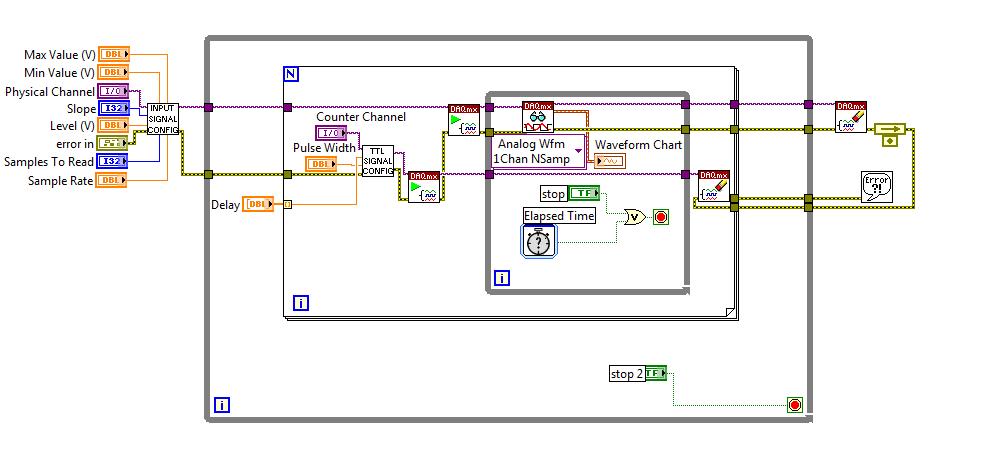
I am currently using a PCI-6251 DAQ card with a block of connection BNC-2120. I have a VI (one that is attached to this topic) that will essentially be an analog input signal and produce digital impulses from the output of the meter to each instant trigger. I am also able to define a series of delay values such that the delay will update automatically each at intervals specified by the user or when you press the stop button. I wonder if there is anyway to change this program as the time-out value will change every instant release. So, for example, in the first trigger a pulse is produced 0 second delay, then immediately when the next instant relaxation is reached, a push will occur with a 0.1 second delay, etc... And I want that the series of the time-out values to keep looping. I tried to use my current VI, with time to stop at each iteration to be less than half of the period, so theoretically it should go to the next delay value in the next instant trigger. Then I tried to put a certain time-loop around it to keep the job going, but it doesn't seem to work. I've attached a screenshot of my attempt, please let me know if this is possible, thank you! To see what each part of the VI in the screenshot, please see the screws attached, thank you!
P.S. for the VI that is attached, the analog input signal is 281Hz, the pulse width is 2.5% of the period and the delay is in the stages of T/20.
No worries,
Please see the attached block diagram image. It is important to wire terminal on the Read.VI DAQmx acquire in a constant to the number ofsamples. This will force this function to wait until many samples are available in the buffer. In my example, you will get 1000 samples per second (because my rate is 1 kHz). and these 1000 were submitted directly to the FFT. What happened for example of you, it is only because you have not specified the number of samples to read, it is by default (-1), which means that the DAQmx Read.vi will pull all the data that is available in the buffer at the time. So if you had only 2 samples in the buffer that your FFT will have only two samples on average and as a result it will fail. Try this and it should help!
-
iMac with Thunderbolt - how to get the old analog inputs
I hang up my old Mac Pro in 2005. I used it to record video cameras and mainly music best of my plate rotating and stereo system - vinyl and CD disks via s-video and RCA cables and Firewire for Mac Pro.
The iMac 27 "new is primary Thunderbolt and I can't find a Thunderbolt conversion box so I can enter my analog input RCA and S-video signals. No indication on the Thunderbolt converters 'both ways' I can't exit analog in the iMAC, then the iMac as well?
They certainly run Final Cut Pro X on the iMAC, then how people get their old media and music in the machine?
I'm about to talk to the local Apple store, but the chances of finding someone who knows what they are talking about with the iMac, Thunderbolt and analog input is going to be a stretch.
Al Donn
You can probably use a converter DV firewire as a Canopus ADVC 110 http://www.bhphotovideo.com/bnh/controller/home?O= & sku = 349146 & gclid = CLSF0_qUnswC FQ8vaQod9VkFFw & is = REG & ap = y & m = Y & c3api = 187... and then an adapter firewire-crush.
-
Input signal is set to +/-0 .5V when it is connected to an analog input
Hello
I have a difficulty connect an analog source to the analog inputs of my acquisition of data (USB-6215). The analog signal is output operational amplifier through a 10 k resistor. I wore the signal out of the amplifiers is 10V peak, I then move the probe across the 10 k (the analog input terminal) and the signal is clipped to +/-0 .5V. If I reduce the amplitude of the signals of source less than 0, 5V Ridge there is no clipping.
Maybe the analog input range the value +/-0 .5V which is causing this as a form of protection? I don't have a LabView to try to change the input range as I do just the wiring.
Analog source is connected to him HAVE 0 and the ground of the analog source is connected to the GND AI.
Thanks in advance.
J
Joel-
Have you tried to read the data through the data acquisition device? If that's what you try to do, I'm curious about what we read.
If you have measurement and Automation Explorer, go ahead and open a Panel to test for the unit and see what are your tensions.
Let us know how it goes.
-
How to merge and write analog inputs, and export data to a tdms file?
I have a vi who writes analog inputs in tdms files. I also want to write the analog output signals, which are 2d table entries in the same PDM file with additional columns representing the analog output signals. How can I get this feature?
Ashaironix wrote:
Hey Crossrulz,
So you're saying that writing two files tdms with entries as HAVE and AO, will write everything in a file single tdms AOs and Ais?
N ° you write in the same file, just different GROUPS. TDMS is a hierarchical data format. You have the file, group, channel. Waveform data will actually in the channel data. But you can have metadata on any level. So, I do a group I and a group of the AO.
Maybe you are looking for
-
I have a worksheet and the SUM function gives the wrong number. It's really dangerous because I need precision. I deduced that there is a single cell, that it fails to include in the sum, even if the cell is selected. I click on the cell, I want to a
-
Portege 3440CT: update my O.S.
I have a Toshiba - Portege 3440CT. My operating system is Windows 98, distributed by Toshiba. Now I need an update for my O.S. and I am looking for Windows 2000 or more. I need a help.Thank you
-
E5-571 news froze during the update of windows
Hi, my 5 E5-571 days old froze during windows update last night, left on the screen to update from one day to the next, had not changed by the morning, had to close it using the manual key, lit a few hours later, still stuck on the same screen to upd
-
BlackBerry Smartphones has stopped receiving e-mail messages
I have a Blackberry Curve 8300 and my ISP is earthlink.net. Everything works fine until today, when I stopped to receive e-mails on my Blackberry. I just checked, and I can send messages very well, of course, but do not receive them.
-
No chance to find the folder on the iCloud drive in CC bridgeBut very easy to find in Photoshop CC and open pictures. However, if I go through my shots in the Finder why should I then download bridge CC... ?