How to delay signals
As part of a larger assignment, I did this 3 bit counter (see attachments). It should output signals in this order:
000
001
010
011
100
(and this should repeat endlessly). But it does not work as expected, I'm stuck.
I think the problem is output triggers to get to folding and, given that the entry is instantly their output.
I struggle to find an element that can delay milliseconds. Any help appreciated.
Hello
In Multisim, there is a component called TRANSPORT_DELAY that allows you to add a delay to your digital signals. It is in the Misc Digital Group and family TIL. Please take a look at the attached example. You can change the delay time by going to the properties of this component and on the value tab, click editing model.
I hope this helps.
Tags: NI Software
Similar Questions
-
How to delay a PXI-5122 trigger before routed to string of PFI
Hello world
I use a PXI-5122 in a PXI chassis. I want to synchronize with two external devices. The first will send a trigger (with a 10 Hz repetition rate) for PXI-5122. Then PXI will generate a trigger (with a constant delay) in the second.
It seems that I need to generate a trigger, then export this trigger to PFI 0 line, but I do not know how to delay triggers with a timeframe of 4µs. I read that there is a slight delay between a trigger on the PFI and the first sample. And the length of the cable is also an important factor to consider.
Could someone give me some suggestions?
Wednesday,
Thanks for the drawings, that helps a lot! Somehow, I see this work (how to set up the scanner):
1. set up the record length to be 12us (4us trigger samples, 8us after outbreak). If the sampling frequency is 100 ms/s, that would be a record length of 1200 samples.
2 configure the position of record reference to 33%. That's how the digitizer breaks 1200 400 samples according to trigger before triggers and 800 samples.
3. configuration of triggering immediate reference. This will allow the acquisition of trigger the moment she gained 400 before triggering samples.
4. export the "reference trigger (Stop)" to send to Device_2. This output pulse is of variable width, so if you want consistency, you will need to the Device_2 trigger the rising edge of the pulse, did not not fall m. Once 400-pre-trigger samples are acquired, this impulse will be sent, and then the scanner will be immediately habitable after initiation of sampling.
5 configure the trigger of the entrance of Device_1 (10 Hz trigger), as the 'Advance trigger' and 'Start Trigger'. This will make the digitizer wait this impulse to start sampling before the next record. We set up, the relaxation of beginning to the 1st record and the trigger in advance for all subsequent records.
This facility should allow a pretty decent timing, but please test to be sure that it will be sufficient for your application.
Kind regards
Nathan
-
Hello everyone.
I have this problem: I do a simulation of the propagation of the signal between a Tx and a Rx, but I need to simulate the delay between the two points. The signal I want to delay is QPSK modulated with the modulation toolkit. The point is to show the original signal from T0 = 0 s, including the delay (same signal but with T0 = delay time in seconds any value).
Thank you
David
That tal Falastiny,
Sin problema pudieras explicarme the situation in Español adelante, como primer idea if you any that generated UN arreglo N elementos con valor 0, mediante the Relación of how many elements present UN segundo, there an este arreglo al final signal that estas simulando agregues para despues visualizarla en the grafica. Te recommend revisar functions to build array y dandole language the CONCATENATE entered opcioon selecciones.
Te Le los foros también los puedes crear en Español, are una gran comunidad you can support. If tienes dudas por favor comenta, saludos.
-
How to delay and trigger output for redeclenchables DAQ
I make redeclenchables data acquisition based on the technique described here and that my departure point couple year I used joint comes with LabVIEW example.
What I realize now is also already done that I need to delay the recognized outbreak and output as a trigger for any other device signal.
How to make a simple diagram:
Trigger is recognized-> DAQ [which works perfect already more than a year]
-> wait 100ms-> exit the trigger [to be added]Using Windows XP edition family, NI PCI 6110
I thank you in advance to anyone interested
-
How the ND_SCANCLK_LINE signal used in DAQmx? It is complete Hold event?
I have moved an old application (using the PCI-6013-OR map) to DAQmx recently, but have some difficulty working. When starting, the signals are configured as shown below.
Select_Signal (1, ND_PFI_2, ND_IN_CONVERT, ND_HIGH_TO_LOW);
Select_Signal (1, ND_SCANCLK_LINE, ND_SCANCLK, ND_LOW_TO_HIGH);I've done the migration as shown below.
Select_Signal (1, ND_PFI_2, ND_IN_CONVERT, ND_HIGH_TO_LOW);
DAQmxExportSignal (TaskHandle, DAQmx_Val_AIConvertClock, "/ Dev1/PFI2");
DAQmxSetAIConvActiveEdge (TaskHandle, DAQmx_Val_Falling);Select_Signal (1, ND_SCANCLK_LINE, ND_SCANCLK, ND_LOW_TO_HIGH);
DAQmxExportSignal (TaskHandle, DAQmx_Val_AIHoldCmpltEvent, "/ Dev1/AIHoldComplete");
DAQmxSetExportedAIHoldCmpltEventPulsePolarity (TaskHandle, DAQmx_Val_ActiveHigh);But my application displays the data in the form of two samples shifted left. I guess that the acquisition has been delayed.
I do correct migration or is there something different in the DAQmx?Documentation OR that I get confused whether ND_SCANCLK_LINE or AIHoldCmpltEvent sample clock. Or is this sample clock?
What is the SCANCLK Signal, and how to use it?
Hope this helps
-
How to connect signals Ni SCB - 264 X
We bought PXI switch 2532 with TB-2641. We also have
bought burst of SCB-264 X. I have a question about the signal
connections. SCB-264 X is supplied with only the connections of signals (C0, C1
etc). But what of the ground for each signal. How to connect the
mass of each signal signal.Thank you
Kitenge
Hi Kitenge,
The connection TB-2641 block creates a configuration of matrix 8 x 64 1-wire for the NI PXI-2532.
1 - wire configurations are typically used for single-ended signals: when he shared there or return a common ground. In these configurations, the constant signal line is usually wired externally (not changed).
If a part of your application requires switching differential signals (2-wire), you can use an additional column for tracking on the ground of each signal. Similarly, additional lines are required.
If all your application passes only signals from 2 threads, then the TB-2643 or TB-2644 may be more appropriate than the TB-2641.
The connection TB-2643 block creates a matrix 4 x 64 2 wires.
The connection TB-2644 block creates a 8 x 32 2-wire matrix.
I hope this helps!
Chad Erickson
Switch Product Support Engineer
NOR - USA -
How the input signal updated step in simulation?
Hello
I have my own model of transfer function. I did first with Matlab/Simulink simulation and succeeded. I use the Signal Generator in Simulink to get out my custom step signal. I modified my step so signal to:
t = 0 y = 0
t = 0.1 y = 0
t = 0.1 y = 50
t = 10, y = 50
t = 10 y = 65
t = 30 y = 65.It's the kind of staircase input signals. Now, how to build such this approach custom signals to be fed in my transfer function. I tried the function 'Not of Signal' of the 'Simulation', but I can only get the 50 and I don't know how to add more "staircase" in my input signals. Could someone help me?
-
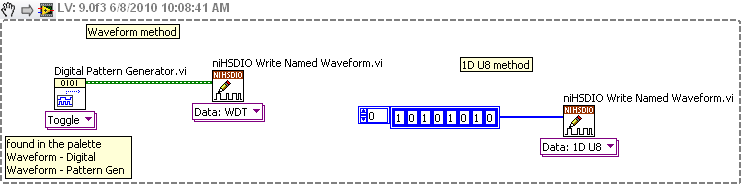
How to generate signals using NI - HSDIO.
Hello
I need to create two signals different pulse square. I don't know how to set their frequencies, number of cycles and FRP using NOR-HSDIO.
Thank you!!
You must create a set of data to send to the HSDIO. It only builds what you send to it. Suppose you want to produce a square on one channel wave. Implement the HSDIO for right channel, trigger, timing, etc. Look at the function HSDIO write nominated Waveform. It says name of waveform, but you can use the polymorphic selector (the area under the function) to select other types of data outside of the waveform, i.e. a table 1 d of numeric (U32, U16, etc.). You must create an arry of data that would be akin to a square wave. Or you could use the input waveform and create a square wave.
The simplest is the waveform because Labview waveform generator functions available. See the image below. If you want to use table 1 d, construct you a table or alternation of 1 and 0 to produce a square wave. The image below is only a partial code. Need to add the rest of the installation HSDIO functions.
-
How two graphic signals, taken at different times on the same chart?
Hello
I am trying to graph 2 files different tdm on a chart. The files are the same
Time Sensor 1 Sensor 2 Difference Sensor 3 03/07/2013 08:26:30.214 AM -0.001 0 0.001 3.2109957 03/07/2013 08:26:31.489 AM -0.001 -0.226 0.225 3.251679525 03/07/2013 08:26:32.249 AM -0.149 -0.198 0.049 3.1567506 03/07/2013 08:26:33.192 AM -0.135 -0.248 0.113 3.315462225 03/07/2013 08:26:34.336 AM -0.135 0.17 0.305 3.2682213 I need graphic of the two signals (time vs 3 sensor data from two different files). The registration of signal rate changes by file and within each file, so I need to keep the time interval between each reading, but a necessity, the two waveforms to chart on each other, no matter what day/time, each file was saved to. Please see attachment for an example.
I can read data from the file and graph several waveforms (generic of generated sine waves) on the same graph, is the part that I'm stuck how to get x/time-axis to work properly.
Thank you
Two options:
(i) use relative time instead of absolute time. If dt is not constant, you cannot use waveforms. Use an XY graph and subtract the time stamp first of each timestamp in the data/file set. Either your departure time will be zero (or 1904 if you want).
(II) draw the two sets of data in a XY Chart, using two x scales. With the right button of the x-scale and select "Duplicate scale" (or something close to it), then go to 'Settings'-> 'Ladders' and change the new scale. Now go to the tab 'Traces' (always in 'settings') and configure your two plots using separate x-scales.
-
 onClicked: {
                    ann.play();//It's an animation
                  // Here i want to add some delat likeThread.sleep() in java. the navigation to second page should happen only after complete the animation.
                    var page2 =second.createObject();
                    nav.push(page2);
                }
I would like to add a few likeThread.sleep () of delay in java. navigation on the second page should fill occur only after the animation.
pls help me.
You can use a signal to detect the end of the animation
https://developer.BlackBerry.com/Cascades/reference/bb__cascades__abstractanimation.html#function-en... -
Hello world. I want to delay an event a few minutes or seconds to not interfere with another event. How can I dow it? Thanks in advance.
Concerning
then you try NOT to delay an event that they prepare.
You can simply use the timer to delay the call to a function that does something with "... another Clip with another sound '."
var t:Timer = new Timer (5000,1);
t.addEventListener (TimerEvent.TIMER, f2);
function f1 (): void {}
addChild (mc1);
t.Start ();
}
function f2(e:TimerEvent):void {}
addChild (mc2);
}
-
How to delay AQ Dequeue Messages
Hello everyone.
I did some research and found the following link for the JCA properties for the AQ adapter documentation.
http://docs.Oracle.com/CD/E15523_01/integration.1111/e10231/adptr_propertys.htm#CIHDFGCD
A property that seems it would be useful for me is the "'
Delay :the number of seconds after which the message is available to the print queue." because my implementation of the QA adapter is withdrawal messages too fast (instances being born a few seconds apart). " Does anyone know how to use this property, or any other way to set a delay between the withdrawal of the messages?Hello
You can use the minimumDelayBetweenMessage property and the adapter.aq.dequeue.threads property in composite.xml
UI:wsdlLocation = "soa_AQ.wsdl" > "
http://xmlns.Oracle.com/pcbpel/adapter/AQ/BPEL/AQ/soa_AQ#WSDL.interface (Dequeue_ptt)"/ > 5000 1 This will ensure that only one thread of AQ adapter removes the message between subsequent dequeues and publishes it's a delay of 5 seconds.
-
How to delay or not to fade the success message?
Hello
I use Apex version 4.2.2. I noticed that error messages do not fade and disappear only if we click on the 'x '. How could I achieve this with the success message? I would like to know how I could delay AND remove the auto fade. After that, I would be able to decide who is best for me. I tried referring here to make the delay, but it doesn't seem to work:
Would it be possible and if yes, where I was able to change?
Thank you.
Hello
I had a situation in which, to have changed the fade time of success messages. You can find the code here: https://gist.github.com/vincentdeelen/7516812
In the setTimeout of this function, the 4000 is the time in mili seconds that the message remains on the screen. You can change this value at your convenience.
If you don't want the successmessage to fade at all, you can create an overload of the function like this:
autoFadeSuccess = function() {return true ;};}
Kind regards
Vincent
-
How to delay delivery of a message
Y at - it an option to write a message and press 'send', but delivery delayed until some predefined time, as I do in Outlook?
Go to the Add-ons page add and search for send later. It allows you to program the sending times.
-
How to delay time for the increase in tension
Hello
I intend to check the wait time when I increase the supply voltage buy using Labview to control the power of Agilent 3631. I wrote a program, the attached file. But it seems that the wait GPIB function does not work for this. Could someone give me a help about it? Thank you
What is your goal in using the GPIB waiting? You wait 50 years? The 1950s that you input is not how long he'll wait. This is a timeout value. You must specify the wait state vector, so that the wait function would like to know when to expect.
If you just want to wait for 50 years, you should just use the function wait (ms) within a single image sequence (with the error thread connect through the framework to enforce the sequence).
Yik
Maybe you are looking for
-
I won a mini iPad 4 generation how to get applecare for my iPad
Hi I have a question I win an iPad mini 4 generation is possible to get Applecare for my mini iPad 4 given that I have not received. Thank you for your support Rolly
-
Do not see the option «Export all Flickr photos»
I'm working on a Mac OS X (MacBook Air) and the use of Logic Pro X (that I started using a few weeks ago). When I try to find the option to export all tracks (which I said is "file > export > export all tracks as Audio files '), it does not appear. I
-
Hello I'm the DAQ Assistant data in a while loop. I need the loop of just work for 600 ms after that it has to stop. I used two Tick account inside and outside the loop (as attached) so that as soon as x - y indicator gets 600 the while loop should s
-
Vista - Error Code: 80070005 (cannot install SP1 KB936330)
I get an error code 80070005 whenever I try to install Windows Vista Pack 1 (KB936330) why that I get this message and how do I solve the problem?
-
Acer Aspire E5-511-P7SJ reinstalled with windows 7 32 bit. Brightness of the screen does not
I use Acer Aspire E5-511-P7SJ windows.81 preinstalled. The system had Intel HD Graphics. I formatted the system and load windows 7 32 bit. After windows 7 installed, I am not able increase or decrease brightness. How can the problem be solved? At pre