How to draw tanks and valves in labview 6
Hi all
I am a beginner in LabVIEW. As a newcomer, I made small programs on the flashing LEDs and check the water level in the tank and so on. Now, I am doing a project on the mixer. While exploring through the examples that I've seen a more or less similar to the HELP option example. In the GUI there are tubes and tanks and valves. Now my question is how I'll be able to draw these pipes, valves etc. in the façade of labview?
Thanks in advance
Rohini
NB: I enclose the photo of the façade.
You asked essentially the same question in July 2010, and it was stated that valves and tanks came the DSC module. If you can not buy it then you need to use Control Editor of LabVIEW to customize the controls. The LabVIEW help describes how to customize controls. You can also search the site FOR examples, like this:
http://decibel.NI.com/content/docs/doc-4819
Tags: NI Software
Similar Questions
-
How to draw marker and ellipses in perspective?
How to draw two ellipses in perspective and in addition the marker on the Center? What are the tools will I need? A tutorial would be very useful. I am beginner in Illustrator.
My desired effect:


You could do this with the one-point-point of view in a perspective grid.
Just draw all flat objects and then drag them into the perspective grid.
In order to draw objects, you can dive into the manual.
See the parts on the shape tools and how to handle the anchor points with the tool pen.
-
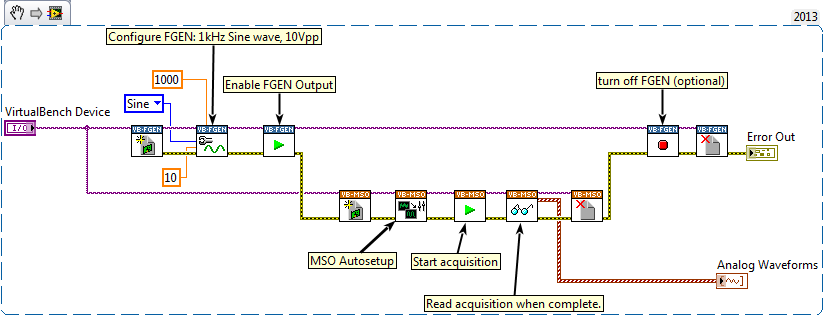
How to connect fgen and mso in labview?
Here's a simple example. You will need to have a BNC cable linking the FGEN and ASM.
This example configures then activates the function generator and then use the automatic setting to configure ASM. The acquisition uses the determined settings of autoconfiguration.
It disables the function generator output once the acquisition occurs. You can remove the FGEN Stop.vi if you want to keep the camera running.
-
How to draw a XY chart in labview 2011
I'm new to labview2011. I need to plot a graph XY where X componnets are counties motor and components are intensity of photodetector which is aquied using materials DAQ 6009. I ' am not able to trace engine count versus intensity always comes to verses intensity. So please help me in this regard, the code is attached
-
How to change a file lvproj in LabVIEW?
Hi all
I have a complex project with a number of specifications of generation. Each of these build sheet has the inside version number in several places. Opening each build specification takes looooong for LV to treat, so the chore of bumping the version numbers on this project is a major pain.
It works:
- Close the project
- Open the .lvproj file in Notepad ++
- Find and replace if necessary
- Save the file
- Open the project in LV
I just wrote a script from LV to do other things before generation and when I try to encode search and replace in labview (with reading from and writing to a text file), the project file will not be opened because it is corrupt.
I guess it's a matter of unicode, but I don't know how to fix it. Any tips?
The XML code is still valid? I think you can tell by opening it in Internet Explorer. Simply make a copy of your .lvproj with the .xml extension and do a file/open in Internet Explorer.
How can you "Find and replace" in LabVIEW? You use the features in xml?
-
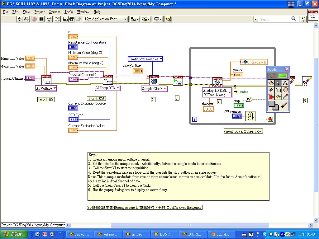
programming LabVIEW 2010 how to scxi 1102 and 1503 cascade in scxi 1101 case
How to scxi 1102 and 1503 cascading if 1101 scxi for labview 2010 programming
just test ok
LabVIEW 2010 latest
-
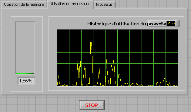
How to check the CPU usage and paging using LabVIEW
Hi guys,.
I build an application that is used to check the CPU usage and paging using LabVIEW. How can I do?
any help, suggestions or advice will be greatly appreciated...
Kind regards
Prashant
Hello
If you plan to build your app for Windows, you can use .NET classes. (System.PerformanceCounter), there is a simple example with LabVIEW:
C:\Program NIUninstaller Instruments\LabVIEW 2010\examples\comm\dotnet\SimpleTaskMonitor.llb
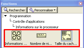
Also, you have several screws that you can use to verify information about the processor.
Kind regards
-
How to down load and use OpenStreetMap offline with LabVIEW 2013
Dear all
How can I download the OpenStreetMap database and API for LabVIEW call this map offline database!
Thank you
Luong.Tran
Thank you!
-
How to draw and the positioning of images in FieldManager using the method object?
How can I add and the positioning of my images in the position desired in FieldManagers?
I need to add more than 2 fields (HorizontalFieldManager/VerticleFieldManager) in my application and I draw an image using the method of painting ovverided.
NOTE: The image will be established if I do not use mainScreen.add (SeparatorField ()) or mainScreen.add (hori2), see below.
If I use mainScreen.add (mainScreen.add (hori2) SeparatorField ())... n then the horizontalFieldManger won't be empty, drawn in the output screen.
import net.rim.device.api.ui.*;
import net.rim.device.api.ui.component.*;
import net.rim.device.api.ui.container.*;
import net.rim.device.api.system.*;

public class BackgroundImage extends UiApplication
{
    private Bitmap backgroundBitmap;
    private Bitmap fieldBitmap;

    int width, height;

    public static void main(String[] args)
    {
            BackgroundImage theApp = new BackgroundImage();
            theApp.enterEventDispatcher();
    }

    HorizontalFieldManager hori2;

    public BackgroundImage()
    {
        //The background image.
        backgroundBitmap = Bitmap.getBitmapResource("jalan_logo.png");

        MainScreen mainScreen = new MainScreen();

        hori2 = new HorizontalFieldManager();

        HorizontalFieldManager horizontalFieldManager = new HorizontalFieldManager(HorizontalFieldManager.USE_ALL_WIDTH | HorizontalFieldManager.USE_ALL_HEIGHT){

            //Override the paint method to draw the background image.
            public void paint(Graphics graphics)
            {
                System.out.println("come to here..!!");
                width = graphics.getScreenWidth();
                height = graphics.getScreenHeight();
                //Draw the background image and then call paint.
                graphics.drawBitmap(width/2, height/2, 150, 40, backgroundBitmap, 0, 0);
                super.paint(graphics);
            }

        };

        //The LabelField will show up through the transparent image.
        LabelField labelField = new LabelField("This is a label");

        //Add the manager to the screen.
        mainScreen.add(horizontalFieldManager);

       mainScreen.add(new SeparatorField());
       mainScreen.add(hori2);
       hori2.add(labelField);

        //Push the screen.
        pushScreen(mainScreen);
    }
}
Help, please.
I have already pointed out the problem with USE_ALL_HEIGHT in first Manager add you to the form. Drop this style bit, otherwise sublayout your screen will generate an exception, and nothing appears!
If you want HorizontalFieldManager to be of a particular size, regardless of the height of managed fields, replace its sublayout:
HorizontalFieldManager fieldManagerTopBanner = new HorizontalFieldManager() { protected void sublayout(int maxWidth, int maxHeight) { super.sublayout(maxWidth, maxHeight); int myDesiredHeight =; setExtent(getWidth(), Math.min(myDesiredHeight, maxHeight)); } protected void paint(Graphics g) { // g.setBackgroundColor(0x000000);//blue g.drawBitmap(100, 150, 100, 200, jlnLogoImg, 0, 0); //g.clear(); super.paint(g); } }; -
I have Adobe Acrobat XI and can not know how to draw a line. I need to redline some documents but can not. Does version XI even not this feature?
Yes, Acrobat Pro XI and standard have this ability.
There is the comment > Annotations > online tool.
There is the comment > Annotations > tool bar.In the Properties dialog box for one, you can select a desired color (i.e. red).
So, in properties, you can check a choice to make this the default value of the tool.Basically, all versions of Acrobat (including the new "DC") offer this feature.
If you work with a scanned image that has been placed in the PDF don't forget to use the OCR to get an output of a 'real' text - Acrobat provides a feature of OCR.
Be well...
-
How to draw the line under STROKE and fill of an object in illustrator cc? Ideas: D...
How to draw the line under STROKE and fill of an object in illustrator cc? Any ideas ...
Aleksandar,
If I (put) understand it, you will need to divide the object. You can:
(1) select the object and Ctrl / Cmd + C + F, and then remove the filling of the copy and the blow of the original;
Draw 2) and drag the new piece down between Division 1 objects) in the layers palette, or select 1 copy) and Ctrl / Cmd + C + F + X + F or similar.
-
You guys should learn how to draw your windows properly on the screen. There is a company called Microsoft which makes my operating system, the guys maybe you should contact them and get advice.
I'm using the latest drivers from Microsoft. Can you ask them to fix the drivers? / s
-
How to implement the wafer map using LabVIEW?
Hello LabVIEW Masters!
I have a project which includes control and searching for information on a PROBER. One of the difficulties I have now is how to implement a WAFER card using LabVIEW. According to the requirements of my client, the element of pads varies between 6 k and 23 k. I guess that do everything (a = a ctl/indicator led) will be a hell of a task, especially on how to effectively manipulate each elements. Does anyone have a better idea on the way whose that?
Please, I seriously need your help...

Thank you and best regards,
Dennis DG
Hi Dennis,
This wafer GerdW post card appears to me as a sort of histogram (for example http://www.ni.com/white-paper/4158/en#toc3);
Altenbach post well this example that shows how to use a plot of intensity to create a 2d histogram:
http://forums.NI.com/T5/LabVIEW/overlay-plots-as-intensity-graph/m-p/211222#M119248
Learn how it works and try to adapt it to your specific task.
Alex
-
How to switch on and Switch Off LED using lab view
How to switch on and Switch Off LED using lab view, I need to Switch on and off material LED, not the soft LED.
I need to know the different ways to Switch On and Off the LED
Hello
I need to control the LED on my laptop which is to have labview, kindly tell the different ways that my laptop a serial port, is possible to control using that.
-
How to draw a box under a trace of waveform?
Hi all
I have a graph of waveform of 3000 point showing a series of peaks. For one of these peaks, for which I know the beginning and end clues, I would draw a box under the waveform on the graph, to highlight its position programmatically. I don't know if there is a way to do it.
I figured out how to draw cursors at the beginning and at the end, but finally I do for multiple peaks, and forest of cursors quickly becomes confused. A simple shaded box works much better.
Any ideas?
Many thanks in advance,
RipRock99
A great thank you GerdW!
The code LV was very close to what I wanted to do and is easy to use to determine how to make my code produces the result I wanted. Basically, I added another form of wave to my chart, using my known indices x to set the values of Y for the areas I wanted to be gray as + infinity and leaving the rest to =-infinity. I then plotted this second graph on top of the original waveform and the property node to set the fill indicator for - infinite.
That does not answer the general question of how to draw a filled rectangle with the coordinates on a graph, but this does not fix what I wanted to achieve.
Bravo and thanks,
RipRock99
PS: I'm including a preview of the result and a snapshot of the code used to define the property node programmatically. I do not understand my code just as it is complicated, and I would also need to add a large set of data. I hope that the pictures are enough to help someone else referencing this Council!


Maybe you are looking for
-
e-mails do not print correctly when you use MS Outlook
I was forced by msn.com to accept an 'upgrade' of MS Outlook Hotmail vice for my msn account. With Firefox Outlook of 19 cars loaded and I can read my email, but I don't get the Outlook buttons for printing, etc. If I try and print a mail with Firefo
-
cannot install Net 3.5 Service Pack 1 audit framework failed. 247478426
Apparently, I installed windows 9 the other night an upgrade also downloaded alvira thought, that I managed to fix service pack1 today, but turbo tax download not because of the problem of "title". under the gun for FAFSA application. Can you help
-
Hi guys,.I am familiar with the creation of 'user variables' and its use in form. And even I used it in the form of variables "Enable dynamic user". But I did not understand the "Context of use" option when creating the user variable. I went through
-
Damaged file - swatch problem?
I'm working on a map of board game showing aerial view of a city. For various reasons, I use different shades for each corner of the roof of the building - the same model basis, but dark for opposite the sun roofs, lighter for those facing towards th
-
How can APEX 5 you add to a Script of the existing Installation of export?
When I create a new image or an external file, the APEX 4, I could go to ' manage supporting objects ', 'create from scratch '. Here, there is an area where I could add my new image/external file to the list of items in the current application in a