How to trigger a digital line?
I would like to use one of my PO lines to turn on/off voltage relay.
I failed to trigger the line via a counter? I would use PFI0 or PFI1
PCI-6035E is the card I have.
This card has only timed software DIO available. This means that you can not use any trigger or the time on the digital. You just write the value you want in the writing of DAQmx and the output to write this value.
Tags: NI Software
Similar Questions
-
NIMAX, how to create a digital line for address GPIO
Please, let me ask you a question about IO port address the NIMAX and PC.
I have an industrial PC with available GPIO ports.
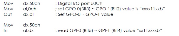
The example of reading and writing address was broadcast on the underside.
address port number is 50Ch.
How can I create the line digital 50Ch in the NOT-MAX.
Thanks for any suggestions.
MAX is useful for the hardware configuration of OR. Since this GPIO is not a product, NOR it will be not configurable in MAX.
-
How to set up digital channels to change values on the trigger and the counter in c#
Hello world!
I work with the driver NI - DAQmx 6025 and want to know, how do I configure the digital channels in c# for control lines different ports by trigger rising "PFI0" and the meter "ctr0.
digitalWriteTask = new Task();
digitalWriteTask.DOChannels.CreateChannel ("Dev1/Port3 / line0:7", "", ChannelLineGrouping.OneChannelForAllLines);
digitalWriteTask.Control (TaskAction.Verify);digitalWriteTask.Triggers / / how to configure to change Digital line on rising "PFI0"?
digitalWriteTask.Timing / / how to configure to change Digital line on County "ctr0?
-------------------------------------------------------------------------------------------------------------------------------------------------------------------------------------------------------------------------------------------------------------------
Hi an alle!
Am mit dem OR-DAQmx 6025 und möchte like wissen, die ich wie digital channels in c# konfigurieren muss um einzelne Ports der Leitungen auf dem Trigger "PFI0" und dem Zahler "ctr0' anzusteuern.
digitalWriteTask = new Task();
digitalWriteTask.DOChannels.CreateChannel ("Dev1/Port3 / line0:7", "", ChannelLineGrouping.OneChannelForAllLines);
digitalWriteTask.Control (TaskAction.Verify);digitalWriteTask.Triggers / / Wie konfigurieren, um den logical Pegel eines feature pine bei der der zu winds PFI0 goods?
digitalWriteTask.Timing / / Wie konfigurieren, um den logical Pegel eines pines beim ctr0 zu go digital?
NEITHER told me, with the NOR-DAQmx 6025 driver not supported!
ICH habe von NOR learn, dass dies mit der 6025 OR AQmx supported wird nicht!
-
How to trigger the new numbering of the lines in a group?
Suppose we have an ORDER_DETAILS table with columns (ORDER_ID, LINE_NUMBER, DESCRIPTION).
We have these lines:
order_id, line_number, description
17: 1, "A".
17.2, 'G '.
17.3, 'R '.
17.4, "Q".
Next, it inserts a new line
17.2, 'K '.
How to trigger the renumbering?
This should be the result after renumbering.
17: 1, "A".
17.2, 'K '.
17.3, 'G '.
17.4, 'R '.
17.5, "Q".
Then we move the line 5 to line 2.
How to trigger the renumbering?
This should be the result after renumbering.
17: 1, "A".
17.2, "Q".
17.3, 'K '.
17.4, 'G '.
17.5, 'R '.
This question is related to another discussion:
https://forums.Oracle.com/thread/1088303
create the order_details table
(number of order_id,
number of line_number,
Description varchar2 (30)
)
rowdependencies;
Start
insert into values order_details (17, 1, 'A');
insert into values order_details (17.2, 'G');
insert into values order_details (17.3, 'R');
insert into values order_details (17.4, 'Q');
end;
Select * from order_details by line_number
ORDER_ID LINE_NUMBER DESCRIPTION 17 1 A 17 2 G 17 3 R 17 4 Q create or replace renumber procedure (number p_order_id)
Start
Update order_details od
Set line_number = (select rn
from (select rowid, RID,)
/ * for autocommit APEX active, etc. * / row_number() on rn (order of line_number, ora_rowscn desc)
/ * for autocommit = OFF favorite above row_number() (line_number order, nulls first ora_rowscn) rn * /.
of order_details
where order_id = p_order_id
)
where rid = od.rowid
)
where order_id = p_order_id;
end;
Start
insert into values order_details (17.2, 'K');
RENUMBER (17);
end;
Select * from order_details by line_number
ORDER_ID LINE_NUMBER DESCRIPTION 17 1 A 17 2 K 17 3 G 17 4 R 17 5 Q Start
Update order_details
Line_number = 2 set
where order_id = 17
and line_number = 5;
RENUMBER (17);
end;
Select * from order_details by line_number
ORDER_ID LINE_NUMBER DESCRIPTION 17 1 A 17 2 Q 17 3 K 17 4 G 17 5 R Concerning
Etbin
-
SMU-6556 - how to control the rise in digital lines (hsdio) time
Hello
Is it possible to control the rise in digital lines SMU-6556 time?
Even in a low frequency 10 kHz signal rise time is 2ns.
TKS,
Hello engfpe,
The SMU-6556 is a 50 Ohm system, which means that the output is source series finished to be 50 Ohms and all our cables and accessories are 50 Ohms. With this configuration, regardless of the flow of data, you should have a clean edge up or down, regardless of the data rate. The quality of the production (edge up or down) on your device is related to the adaptation of impedance of your cables.
The SMU-6556 cannot adjust the speed of scanning by itself. However, you can insert simple passive components to do it for you. I have attached below the images. The first is a diagram showing a way to slow down the edge. The second is the a waveform simulation showing the rate of original edge before it slows down and the edge of idle. This simulation is not the SMU-6556 but rather a generic digital output for concept. In the schema that R1 is set on 34 Ohms because U1.8 has the 16 additional Ohms on the inside. TL1 is the output of 50 ohms simulating the cable on the SMU-6556. R2, R3, and C1 are components, you can insert after the SMU-6556 twist before moving your device/cable. In this configuration from cable to your device is TL2 which is also 50 ohm, but it could be another impedance in which case you would change R3 to match.
You can see in the attached images, you can slow down significantly the edge with this configuration by altering the C1. I hope this helps.
-
Hello!
My problem appeared when I tried to update my traditional NOR-DAQ legacy code to DAQmx.
I use 2 meter (meter 5 and 7 meter) on PCI-6602, to generate trains of pulses, as well as the lines of e/s digital port 0 (the form lines from 0 to 7). What I do in my request, it's that I'm starting to generate the pulse train on the output of 2 meters and after that I play with the State of digital lines.
Traditional, it was no problem to use the meters and digital lines at the same time, everything went perfectly, but in DAQmx, is not possible.
What's happening: I start generating train of pulses on the output of counters, no errors, but when I try to change the State of a line of digital port the generation of the pulse train is stopped. What happens when I start the task associated with the digital way.
My question is: is it possible to create a channel on digital lines without changing the channels created for meters?
Another thing that I managed to do with the panels 'Measurement and Automation Explorer' and Test for PCI-6602, is basically the same thing, I generate trains of pulses on the output of the 7 meter and try to start a job on the digital line, but I get an error:
"Error-200022 occurred in test Panel.
Possible reasons:
Measurements: Resource requested by this task has already been reserved by another task.
Device: Dev4
"Terminal: PFI8.On the contrary if I use the counter 0 or a counter 1 to generate trains of pulses I encounter the same problem.
What resources are used by 2 to 7 of the PCI-6602 card counters and the counters to 0 and 1 do not use?
Thanks in advance for any answer!
Ciprian
After doing some real tests on this device, I found that it is a normal behavior for the jury of 6602. This is because when you start a task digital all 32 lines are configured for digital i/o, so it replaces your meter operation. The article below the link explains a little more on this subject. You must start the digital task before the task of counter to use the features of both in your program.
2 meter and above will not work correctly when you perform digital i/o on NI 6601 or 6602
http://digital.NI.com/public.nsf/allkb/43F71527765EEC3886256E93006CD00C?OpenDocument
-
CompactDAQ using to acquire correlated data force-position began with a trigger of digital material?
Hello
up to now, I use a PCI NI6221 card to acquire the data of time - correlation of two analog inputs and an encoder (line A and B), i.e. to get two supply voltages and position for each sample. The beginning of the acquisition is hardware-triggered by a digital line of PFI.
In addition to assessing the encoder inverted /A lines and / b (to eliminate the errors of counting in harsh environments) I want to migrate this task to a CompactDAQ 9172 module with a 9205 (for analog), a 9411 (for incremental encoder signals) and a 9472 (for outputs digital additional static) inside.
My question: is it possible to use the entry PFI0 of the 9205 as trigger of digital material to make an acquisition described above? Or how should I continue?
Best regards
cpschnuffel
I would like to make a correction to my last post... we have actually supported for triggers the 9205 (analog and digital) to any location in the 9172. Digital lines has always obey the same rules I mentioned earlier.
So, you can trigger off the 9205 PFI line in any location, or outside either module in slot 5 or 6.
I'll be sure to amend article KnowledBase that I've referenced once I have the chance to make it clearer and more thorough.
-John
-
How to get Dolby Digital 5.1 sound on Qosmio?
I wonder how to sound Dolby Digital 5.1 Qosmio. Whenever I play an original DVD movie, all I can get is Dolby Prologic 2. Have a link with DRM? I use Thomson mini plug opto cable. Home Theater receiver accepts digital input but does not have 5.1 sound. The movies that I download with DRM removed HD forums gives the same results. Where is the problem?
Thank youHello
The line line and S/PDIF audio headset uses the same output.
It is possible to connect the audio/video receiver via SPDIF optical cable.
http://www.LaCie.com/products/product.htm?PID=10739 -
DAQmx Read simultaneous calls on the same digital line
Hi all
I use v10.0 LV 32-bit on Windows 7.
I use DAQmx Read (in a task) to check the value of a digital line. Is it OK to do this in two different locations in a program at the same time for the same digital line? Or I have to put a wrapper around reading to force operations to be sequential?
Thank you
ZolaWhen you need to expose the capabilities of resources to multiple areas within a project (expand the scope of a resource) it is common to wrap the resource in an Action engine to encapsulate the resource functions. See here for an example of a 'Module on resources' material and a discussion animated about how this code help development construction and avoid resource conflicts. If you have not read famous nugget again – he of Ben is a link in my tag "Required_Reading".
Or more directly. Yes, you should encapsulate these readings DAQ to avoid suspended
-
A SIMPLE change: reading a digital line instead of 4 ports
Hello
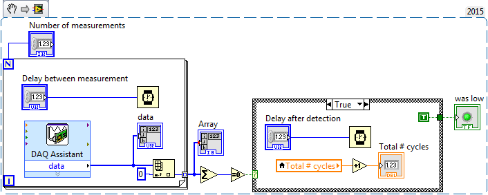
I found this application (see sippet) who read four digital ports and then add them in table 1 + and every time the sum of the array is 0.
I'll just check on a digital line. When I change the Assistans DAQ to digtial line entry port, it turns into a Boolean value. But how can I change the settings I only compare the line including propely is 1 or 0. ?
Thanks in advance.
If I understand your question, you can replace only the elements of the array add and equal to 0 with just one or elements of the array.
-
Outbreak of several digital lines of a single window using PCI 6353
Hello
I use a PCI 6353 to control a laser for a PIV system. The laser requires 4 pulses (F1, F2, T1, T2) on different channels. It would be easy using 4 counters on the Board, but I also need to trigger the camera. The card has a lot of output digital, so I thought I could use 2 meters and four digital outputs.
I thought that, by setting the pulse counter from 0 at a time duration between F1 and T1 and triggering a rising edge and T1 F1 a front down using output internal), I would be able to solve the problem. However, the system I cannot trigger the two lines of the same internal output. I don't know why. I have attached two vi, one for a single channel that works very well and the other with two channels. I am also attaching a diagram of approximate time of my proposed solution.
I am not absolutely put on this format, so if this is not possible and you have another solution, please let me know. Accuracy is the key here, the widths of pulse being about 1 microsecond and the intervals between F1 and Q1 being approximately 10 microseconds, so I think the hardware timing is essential. However, I'm not quite clear on interact it with the digital pulses and counters.
Kind regards
Joe
Hey Joe,
All the lines that you want to use for quick time ARE on the 6353 must be in the same spot. Unfortunately, you can't start or clock several lines independently.
That said, I think that the simplest solution would be to simply create a waveform suitable for generating all 6 signals with. You should be able to clock up to 10 MHz, which gives you 100 ns resolution. If you need 1 us resolution, then you could get by synchronizing the c to 1 Mhz. While you could technically use a combination of counters and to get what you need, it should not be necessary in your case. All you need is a single task with the waveform appropriate to generate your desired signals.
Best regards
-
How to write a single line instead of the entire port?
Hello
I followed the example for writing to the digital line as follows
int taskHandle;
given int [8];
char linename [] = "" dev2/port0 / line0:7 ";"
DAQmxErrChk (DAQmxCreateTask ("", & taskHandle));
DAQmxErrChk (DAQmxCreateDOChan (taskHandle, linename, "", DAQmx_Val_ChanPerLine));
DAQmxErrChk (DAQmxStartTask (taskHandle));
DAQmxErrChk (DAQmxWriteDigitalU8 (taskHandle, 1, 1, 10.0, DAQmx_Val_GroupByChannel, data, NULL, NULL)); Here the data have 8 digits
Error:
SetWaitCursor (0);
If (DAQmxFailed (error)) DAQmxGetExtendedErrorInfo (errBuff, 2048);
If (taskHandle! = 0)
{
DAQmxStopTask (taskHandle);
DAQmxClearTask (taskHandle);
}
If (DAQmxFailed (error)) MessagePopup("DAQmx Error", errBuff);The example above shows how to write 8 binary to 8 lines, but how to write only one line? I try the following code, but it does not work
char linename [] = "dev2/port0/line 2;
...
DAQmxErrChk (DAQmxWriteDigitalU8 (taskHandle, 1, 1, 10.0, DAQmx_Val_GroupByChannel, & data [2], NULL, NULL)); Here the data have 8 digits
The data format for the DAQmxWriteDigitalLines() function will do exactly what you want.
The data format for the DAQmxWriteDigitalU8() function is a full port (even if you do not have a value of a harbour full of lines in your task).
-
How can I get digital signals (interface UART) with a microcontroller with NI USB-6008?
I have acauired a few analog signals by A/D (3 channels). I put each scanned data on 3 digital output with a microcontroller. I want to see if it is possible to import these digital outputs 3 to a PC via a USB-6008? It's like the connection of the output to the digital input of the USB-6008 and import the 3 channels simultaneously to LabView? Do I need to use some other hardware like USB-8451 and connect the clock of the MCU to USB-8451?
Saraydin,
The digital I/o on the USB-6008 is a software program only, so unless your signals are rather slow, it probably will not work for you. In general, the procedure would be to connect each signal to one of the digital lines on the map and then set up a digital entry into LabVIEW task to read the three channels. If you use a device that has clocked by the digital i/o hardware, you then your input clock signal and use it as the sample for the task clock. Here is a list of USB devices supporting DIO clocked by the hardware. Also, there is an example that comes with LabVIEW, which shows how to do this. You can get to it in LabVIEW by going to help > find examples. When the example Finder window opens, navigate to hardware input and output > DAQmx > digital measures > Cont read dig Chan-Ext Clk.vi.
The 8451 is specifically for I2C and SPI, and would be great if you try to make one of these protocols, but otherwise I would recommend the devices in the list I linked above.
-Christina
-
How can I change the line spacing?
I looked everywhere to find how I can change the line spacing in my e-mail address when sending. Can't find any dishes. CAM help me?
The answer is probably some handmade css coding which is not a trivial thing to do.
Why you want to change the line spacing? A larger or smaller font would be useful for you?
-
How to develop and reduce lines or groups of lines in figures?
How to develop and reduce lines or groups of lines in figures?
Thank you
Casey
Select the rows (or columns):

Then, place the cursor on one of the row headings (the numbers on the left):

so that you see the carat facing downwards, then click here to bring up the context menu for the lines:

then select "hide selected rows.


Maybe you are looking for
-
INSTALLATION OF TIME CAPSULE AIRPORT
THE CAPSULE FROM THE AIRPORT CAN BE PLUGGED INTO A ROUTER/MODEM BOX OF COMBINATION OR WHAT I HAVE SEPARATED THE ROUTER AND MODEM?
-
Logical string/Message in VBAI
Experts AND good day, I have a little problem with the logic of the chain. What I mean is that I have two 2 entered string. I have a priority and replace the string. My output message must be what, priority message contains. But where priority messag
-
MMS.cfg [unsolved] not recognizing AVHardwareEnabledDomain
Information and VersionsWindows 7 SP1Firefox 19.0.2.0Flash Player 11.8.800.168ProblemWe have a SharePoint page that has a link to open the webcam and attach a photo. We want that all users of this device, current and future profiles, allowing access
-
Convert text fields to the data fields
Hi, I have a large PDF with dozens / hundreds of fields 'text' which I want to change fields of data with a domain name so that I can auto fill a database. Is there an easy way to do this? They need not be specific names, Field1, Field2, field3 etc.
-
I checked in lightroom programs and it says that it is up-to-date, why can't switch to lightroom 6