Implementation of the circular buffer for LabVIEW 8.5
Greetings,
Several weeks ago, I downloaded the application of a circular buffer for LabVIEW 8.5 of ni.com. The current Web page is:
http://zone.NI.com/DevZone/CDA/EPD/p/ID/5883
Unfortunately, this Web page has been updated since then and the files available for download (swcircularbuffer1.0.19.zip) are for LabVIEW 8.6.
So my question is: where can I find the application of a circular buffer for LabVIEW 8.5?
Thank you very much!
Telmo
The library in 8.5 is attached.
Tags: NI Software
Similar Questions
-
I use the outgoing/incoming analog DDK with the DAQ 6341 SMU map.
The examples, for example aoex5, show a single timer (method outTimerHelper::loadUI), but the example shows the DMA loaded with same size of vector data.
There is a comment in the outTimerHelper:
 call rogramUpdateCount, which implies that memory sizes different pad per channel can be used.
(the comment is: switching between the sizes of the various buffers is not used)
Nobody knows what should be the format the DMA buffer for data from multiple channels with different frequencies?
For example, we want a0 with a sinusoid at 1 kHz and a1 with a sine wave of 1.5 Khz. What looks like the DMA buffer?
With the same frequency for each channel, the data are interleaved, for example (ao0 #0, ao1 #0; ao0 ao1 #1, #1,...), but when the frequencies for each channel is different, what the stamp looks like?
Hello Kenstern,
Data are always intertwined since each card has only a single timing for each subsystem engine.
To AO, you must specify the number of samples that will be released to the AO. You also specify the number of channels. Because he didn't is that a single engine timing for AO, each AO will be channel will be updated at the same time to update clock tick. Data will be interlaced exactly as shown in the example because each channel AO needs output at each tick of the clock to update. The data itself can change depending on the frequency you want to copy.
kenstern wrote:
For example, we want a0 with a sinusoid at 1 kHz and a1 with a sine wave of 1.5 Khz. What looks like the DMA buffer?
With the same frequency for each channel, the data are interleaved, for example (ao0 #0, ao1 #0; ao0 ao1 #1, #1,...), but when the frequencies for each channel is different, what the stamp looks like?
In your example, you must come with an update rate that works for the two waveforms (sine waves of 1 and 1.5 KHz). To get a good representation of a sine wave, you need to update more than 10 x faster than your fastest frequency... I would recommend x 100 if possible.
Update frequency: 150 KHz
Channels: 2
Then create you stamps that include complete cycles of each wave you want to produce based on the frequency of update. These buffers must also be of the same size.
Buffer 1: Contains data for the sine wave of 1 KHz, 300 points 2 cycles of sine wave
Buffer 2: Contains data for the sine wave of 1.5 KHz, 300 points, 3 cycles of sine wave
You can Interleave them as before. When the data are performed through the ADC, they are out different sine waves, even if the AO channels are updated at the same speed.
-
Smart way to save large amounts of data using the circular buffer
Hello everyone,
I am currently enter LabView that I develop a measurement of five-channel system. Each "channel" will provide up to two digital inputs, up to three analog inputs of CSR (sampling frequency will be around 4 k to 10 k each channel) and up to five analog inputs for thermocouple (sampling frequency will be lower than 100 s/s). According to the determined user events (such as sudden speed fall) the system should save a file of PDM that contains one row for each data channel, store values n seconds before the impact that happened and with a specified user (for example 10 seconds before the fall of rotation speed, then with a length of 10 minutes).
My question is how to manage these rather huge amounts of data in an intelligent way and how to get the case of error on the hard disk without loss of samples and dumping of huge amounts of data on the disc when recording the signals when there is no impact. I thought about the following:
-use a single producer to only acquire the constant and high speed data and write data in the queues
-use consumers loop to process packets of signals when they become available and to identify impacts and save data on impact is triggered
-use the third loop with the structure of the event to give the possibility to control the VI without having to interrogate the front panel controls each time
-use some kind of memory circular buffer in the loop of consumer to store a certain number of data that can be written to the hard disk.
I hope this is the right way to do it so far.
Now, I thought about three ways to design the circular data buffer:
-l' use of RAM as a buffer (files or waiting tables with a limited number of registrations), what is written on disk in one step when you are finished while the rest of the program and DAQ should always be active
-broadcast directly to hard disk using the advanced features of PDM, and re-setting the Position to write of PDM markers go back to the first entry when a specific amount of data entry was written.
-disseminate all data on hard drive using PDM streaming, file sharing at a certain time and deleting files TDMS containing no abnormalities later when running directly.
Regarding the first possibility, I fear that there will be problems with a Crescent quickly the tables/queues, and especially when it comes to backup data from RAM to disk, my program would be stuck for once writes data only on the disk and thus losing the samples in the DAQ loop which I want to continue without interruption.
Regarding the latter, I meet lot with PDM, data gets easily damaged and I certainly don't know if the PDM Set write next Position is adapted to my needs (I need to adjust the positions for (3analog + 2ctr + 5thermo) * 5channels = line of 50 data more timestamp in the worst case!). I'm afraid also the hard drive won't be able to write fast enough to stream all the data at the same time in the worst case... ?
Regarding the third option, I fear that classify PDM and open a new TDMS file to continue recording will be fast enough to not lose data packets.
What are your thoughts here? Is there anyone who has already dealt with similar tasks? Does anyone know some raw criteria on the amount of data may be tempted to spread at an average speed of disk at the same time?
Thank you very much
OK, I'm reaching back four years when I've implemented this system, so patient with me.
We will look at has a trigger and wanting to capture samples before the trigger N and M samples after the outbreak. The scheme is somewhat complicated, because the goal is not to "Miss" samples. We came up with this several years ago and it seems to work - there may be an easier way to do it, but never mind.
We have created two queues - one samples of "Pre-event" line of fixed length N and a queue for event of unlimited size. We use a design of producer/consumer, with State Machines running each loop. Without worrying about naming the States, let me describe how each of the works.
The producer begins in its state of "Pre Trigger", using Lossy Enqueue to place data in the prior event queue. If the trigger does not occur during this State, we're staying for the following example. There are a few details I am forget how do ensure us that the prior event queue is full, but skip that for now. At some point, relaxation tilt us the State. p - event. Here we queue in the queue for event, count the number of items we enqueue. When we get to M, we switch of States in the State of pre-event.
On the consumer side we start in one State 'pending', where we just ignore the two queues. At some point, the trigger occurs, and we pass the consumer as a pre-event. It is responsible for the queue (and dealing with) N elements in the queue of pre-event, then manipulate the M the following in the event queue for. [Hmm - I don't remember how we knew what had finished the event queue for - we count m, or did you we wait until the queue was empty and the producer was again in the State of pre-event?].
There are a few 'holes' in this simple explanation, that which some, I think we filled. For example, what happens when the triggers are too close together? A way to handle this is to not allow a relaxation to be processed as long as the prior event queue is full.
Bob Schor
-
How to execute the Matlab executable for Labview
Hello
I have a Matlab executable 'Report_GUI.exe', its a GUI that takes an entry (a file) and generate the data report. I want this GUI executable to run through my program Labview DAQ. I'm unable to find appropriate ways to do so. Can you please help me out on this, is there any example for what I can watch it. Please let me know.
Thank you
Ankit
AnkitG wrote:
Hello
I have a Matlab executable 'Report_GUI.exe', its a GUI that takes an entry (a file) and generate the data report. I want this GUI executable to run through my program Labview DAQ. I'm unable to find appropriate ways to do so. Can you please help me out on this, is there any example for what I can watch it. Please let me know.
Thank you
Ankit
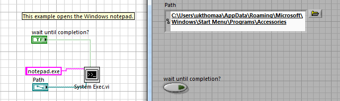
Hey Peter,
You can open external .exe files in a LabVIEW program using the System Exec VI. You can find an example of this kind of operation in the Finder for example of NOR (help > find examples...) under communicate with external Applications.
All you need to provide to the terminals of the system Exec VI entry is the name of the .exe that you want to open, and a reference to his repertoire of records;
LabVIEW will do the rest of the book. For additional parameters with respect to the arguments of the command line you may need, after the entry of the file name in the attribute of the VI string, you must type a hyphen (-) followed by the name of your parameter; for example, ' notepad.exe - myFirstParameter.
Let me know if you need help a full tutorial of this operation are located at this URL.
Good luck!
-
I downloaded a zip file of the site NOR: swcircularbuffer1.0.19.zip and unzipped the file and then ran the installation exe to install this item. The installation of the popup screen briefly explains that the installation program will install circullar buffer library and examples and turns to the next screen, which tells the user where the software will be installed. The next screen is weird! 'Start Installation, check the following before continuing summary' and "Summary of Installation no software will be installed or deleted" and no option to continue to the next screen! This is one heck of an installer! I see this download of OR does not work. Maybe it's just because I have a 64-bit computer that was a problem I had once before, when I tried to install a parser of VI that was not yet made for the 64-bit version. I'm still waiting for this update, but I would try this tool. Any ideas?
It's very strange! Setup works for you, but not for me! I downloaded the zip twice and I tried to run the Setup file and the installer simply does not and I installed several products NOR on this computer and the installation files everything worked as expected. What do you mean 'free file '? And the content of the archive is: bin, license & supportfiles directories and a readme file setup.exe. I do not think that this will be of any help, put the latter in the directory/file
. -
Run the time allowed for Labview applications
Can I need separate licenses to run for each application that I distribute to which I built in LabVIEW 8.6?
Hi Jim Heath...
you only need a license to develop and build the application. The runtime is free.
Mike
-
Where can I find the download link for Labview 7.1?
I'm not find labview 7.1 on the site of national instruments.
I appreciate if someone helps me with the link.Thank you
[email protected] wrote:
woahhhh
Thank you
but I'm looking more for the evaluation version of article 7.1. In this connection, I have to activate it.No, you don't. LabVIEW 7.1 was the latest LabVIEW version that does not require an activation method. Heck it does not even require a serial number. It will keep nagging you saying something like 'if I noticed I don't have a serial number you want to enter a' and if you say that it's just like 'it's cool maybe next time bro
Last secret. LabVIEW 7.1 was also the last version that you could put in a random series of and as long as it was in the right format it would be happy and unlock all the features of LabVIEW. It goes back again to the fact that there is no activation and it no way of knowing if the series you entered was one that you own it or not.
-
Change the default font for LabVIEW front style
For some reason, my IDE did my front italicized by default policy. When I add a new indicator of control /, / add a stand-alone commentary, I have italics.
I don't know how it happened, or how to cancel it. Help, please? (With the help of LabVIEW 2013 SP1)
Gah, as soon as I make a forum post, I found the answer:
If I open the font dialog (Ctrl + 0) without any selected text, I get a dialog box "Panel by default are". Which allows me to set the default value. I must have accidentally used it when trying to format a front panel.
-
How to use the class IIA for LabVIEW driver wrappers?
Hi all
I've read some texts on IVI compliance, but I have not quite how I wrap an IVI - COM to an IVI - C. Where is this done?
In MAX, I see:
-Configuration-> software-> IVI Compliance Package 3.3
But no properties in there...
I have an analizer spectrum available drivers are only IVI - COM, but I want to wrap them up in IVI - C...
can someone tell me step by step how can I do this?
or maybe tell me some beginner tutorial?
Kind regards
JPLO
Hello JPLO,
Before trying to communicate with your instrument using any sort of instrument drivers, you must confirm that you can connect at a lower level. In most cases, this means through VISA, using MAX. IVI - COM driver installation program should add a software module to the IVI Configuration, which is the MAX. Most installers IVI - C also adds a pilot session, but you'll need to create a.
We include adaptors IVI - COM for class IVI - C with PKI pilots. Here's a knockout who talk about them: IVI-C class for specific drivers IVI-COM driver Support
You can also simply treat the IVI - COM driver like any other ActiveX object.
What type of instrument you are using?
See you soon,.
NathanT
-
Install the hardware support for LabVIEW
When updating to LabVIEW 2013, I asks me to install the appropriate device drivers, but I don't know where to find them.
On the DVD device driver provided with LabVIEW. Or you can to http://www.ni.com/download/ni-device-drivers-2013.02/3802/en/downlosd.
-
The serial port for LabView 7 drivers work on Windows 7
I created an application using LabView 7.1 that has run on Windows XP. I tried to install this application on a Windows 7 PC to base and the communications port series is no longer works. I installed the latest version of NI-VISA but still does not work. By reading the other discussions, upgrade to a new version of LabVIEW is necessary but there at - there another solution?
There is no work around. The latest version of VISA can't LabVIEW 7. The first version of NI-VISA, which supports Windows 7 is 4.6, and doesn't not support LabVIEW 7. You need to upgrade to LabVIEW or use an older operating system.
-
Version of the C API for LabVIEW FPGA 2011
What is the version of the C API that will work with LabVIEW FPGA 2011?
I guess as this one: http://www.ni.com/download/fpga-interface-c-api-2.0/2616/en/
Version numbers seem to start by 2012 years. It's the latest version I could find before 2012 and he was released in August 2011. This time coincides with the annual festivities of the NOR week where a large part of the software/hardware is released. It's a small download, so it shouldn't be difficult to download it and try it.
But, you'll still need LabVIEW FPGA development according to this white paper: http://www.ni.com/white-paper/9036/en/
-
Implementation of the popular statistics (for example most downloaded document) in Oracle UCM
Hello everyone,
I need to implement things followign in Oracle UCM:
1. most popular searches.
2. latest added documents.
3. document noted.
4. most of the downloaded documents.
4. similar documents (even if the user has opened a)
and other content, tracking features.
I need emergency aid.
Thanks in advance.Prashant,
You must implement your own algorithm of proximity. I'll try to use database query capabilities.
Good luck!
Jakub -
Implement the Std::Vector < < Point2i > > Std::Vector in dll wrapper for LabVIEW
Hi, I'm writing a wrapper dll that using OpenCV function. I had been sucessfully implement Std::Vector
by referring to "An array of clusters to a dll C sending". And now, I want to implement the Std::Vector<>
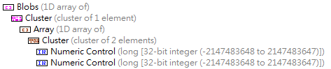
> who is a lot like table 2D but each line items may be different. In LabVIEW, I attribute a range of cluster of the dashboard cluster of 2 I32 elements, structure which is shown below:
I think it has the same functionality as Std::Vector<>
> in C++. So I plug this data on the "Call library function node" structure and generate C code that indicated below:
/* Call Library source file */

#include "extcode.h"

/* lv_prolog.h and lv_epilog.h set up the correct alignment for LabVIEW data. */
#include "lv_prolog.h"

/* Typedefs */

typedef struct {
    int32_t elt1;
    int32_t elt2;
    } TD4;

typedef struct {
    int32_t dimSize;
    TD4 elt[1];
    } TD3;
typedef TD3 **TD3Hdl;

typedef struct {
    TD3Hdl elt1;
    } TD2;

typedef struct {
    int32_t dimSize;
    TD2 elt[1];
    } TD1;
typedef TD1 **TD1Hdl;

#include "lv_epilog.h"

void funcName(TD1Hdl arg1);

void funcName(TD1Hdl arg1)
{

    /* Insert code here */

}
Then, I write this code show below in dll wrapper:
void funcName(TD1Hdl Blobs) { vector < vector> blobs; // Distribute contents of blobs to Blobs from LabVIEW MgErr err = mgNoErr; size_t arraySizeInBytes = Offset(TD1, elt1) + sizeof(TD2)*blobs.size(); // Determine row size err = DSSetHSzClr(Blobs, arraySizeInBytes); if (err != mgNoErr) return; (*Blobs)->dimSize = blobs.size(); for (size_t i = 0; i < blobs.size(); i++) { arraySizeInBytes = Offset(TD3, elt) + sizeof(TD4)*blobs[i].size(); // Determine col size of each row err = DSSetHSzClr((*Blobs)->elt[i].elt1, arraySizeInBytes); if (err != mgNoErr) return; /*......................*/ } } When I call LabVIEW dll, the program get interuption(i.e shutdown) on line where I want to determine the size of each row.
Could someone give me some suggestions on this subject or promote another application of this requirement?
Thank you very much.MgErr funcName(TD1Hdl Blobs) { vector < vector> blobs; Labeling(image_binary, blobs); // the prototype of this function is: Labeling(Mat &binary, Vector Personaally I've usually done like this. Already, the tar of DSSetHSzClr() indicates if there was something wrong and that the handle cannot really become NULL to call this function.
To be entirely correct and safety integrated, you must do more than that. But as long as you assume that the incoming picture is always smaller that the outgoing Board will be (usually it be 0 items when you enter this function, but if you reuse sort table in the diagram, by storing it in a registry change for example, this may not be true more) this will be enough.
-
Increase the length of size and recorder circular buffer
Hello again!
First of all:
I have a problem with the circular buffer.
I was able with a sampling frequency of 1000 Hz I used 6 circular buffers, each with a size of buffer for 30 minutes. It was no problem for the PC. I do not have such a high sampling rate, but I need a buffer size that is larger, something between 90 and 120 minutes with 8 pads. so I decided to reduce the sampling rate of what I need, it's 50 Hz. Because I reduced the sampling rate to 1/20 of the original sampling frequency I thought that a buffer size of 120 minutes should be possible.
Now, after trying the new sampling rate, I still can't use the 8 pads with more than 60 minutes. Any ideas why I had this problem? How can I provide a larger buffer, no possibility?
Second:
I use the recorder for display. I would like to display voltage in the long term. With the recorder the maximum length is approximately 3.5 hours. How can I view on longer periods? What I need to display the length in days. Is this possible? Perhaps with the other modules or almost?
That's it for now, thank you a lot for the useful tips.
Good day!
Good bye
The maximum time width of the graphic recorder or Y/t diagram is a function of memory (RAM) on the computer, the number of channels to display and the sampling frequency. Dynamically, the memory is allocated to the maximum. To avoid using RAM available on the computer, DASYLab is limited to half of the memory of the computer.
That being said... How you appear more time? You can reduce the number of samples using average or separate modules - in effect, reducing the sampling frequency. Alternatively, you can consider if the trigger on demand and a relay may be able to effectively reduce the samples for data to slow evolution.
Some clients have two screens high resolution on a shorter and more low resolution over a longer period.
Maybe you are looking for
-
How can I send a hyperlink by post accompanied by a simple right-click?
On my old laptop I had outlook and express home XP. If I find something I want to share I just had to click right and then you had the opition "send link by mail". Very nice feature! How does this with windows 7 with Firefox and Thunderbird?
-
Satellite A300 - BIOS downgrade after upgrading the BIOS
I did an upgrade of BIOS of victory of version 1.6 of 2.10 - at the recommendation of the Toshiba site, for my laptop A300 1N0 - model PSAGUE.Touchpad no longer works. I have 2 operating systems, XP and W7 is the same. I start the laptop with the Win
-
Router WRVS440N wireless and tablets
Tablets (Kindle, Galaxy Note) does not connect to the router via DHCP settings, and if the static settings are entered, it connects to the router, but does not connect to the Internet. Can anyone help with this? Are the incorrect router settings? N
-
Hello My computer meets all the requirements to aero but does not have aero in option on the appearance. I tried many things and have gone through the procedures step by step, but I still don't have aero in option on my vista. Any idea?
-
Hello IAM trying to select items in a list.I created the list by using the following code. MyList = new ObjectListField();MyList.set (myarray);Add (myList); My problem is how to select items to mylist. Thank you in advance.